
International Research Journal of Engineering and Technology (IRJET) e-ISSN:2395-0056
Volume: 11 Issue: 07 | July 2024 www.irjet.net p-ISSN:2395-0072

International Research Journal of Engineering and Technology (IRJET) e-ISSN:2395-0056
Volume: 11 Issue: 07 | July 2024 www.irjet.net p-ISSN:2395-0072
Irfan Amin Gadai1, Elif Altürk2*, Isilay Bilgic3
1 Automotive Electronics and Intelligent Vehicles Department, Faculty of Engineering, Istanbul Okan University, Tuzla, Istanbul, Turkey
2 Electrical and Electronic Department, Faculty of Engineering, Istanbul Okan University, Tuzla, Istanbul, Turkey
3 Electric and Energy Department, Vocational School, Istanbul Okan University, Tuzla, Istanbul, Turkey
Abstract
Inthisstudy,acomprehensiveexaminationofbatteryandsupercapacitor-basedhybridenergystoragesystems(HESS)is conducted to enhance the performance of electric vehicles. By utilizing MATLAB Simulink as the primary analytical tool, wecomparetheefficienciesoffullyactiveandpassivehybridenergystoragesystems.Theprimaryobjectiveistointegrate thepowerdensityofsupercapacitorswiththeenergydensityofbatteries,aimingtoachievesuperiorperformancemetrics for electric cars. Our findings reveal that the fully active hybrid energy storage system demonstrates a more efficient power management capability, outperforming the passive system by generating over 41% more power under identical load conditions. This research not only underscores the potential of full-active HESS in electric vehicles but also sets a foundationalbaseforfutureinvestigativeendeavorsinthisrapidlyevolvingfield.
Keywords: Electric Vehicles, Hybrid Energy Storage Systems, MATLAB Simulink, Performance Enhancement, Supercapacitors
1.INTRODUCTION
The gasoline vehicles are an integral part of this world as they provide convenience and mobility to almost everyone. However,thisconvenienceleadstopollutionandanincreaseingreenhousegas(GHG)emissionsduetothecombustionof gasoline.Therehavebeenmanystudiesthatindicatethattheenvironmentisnegativelyaffectedbygasolinevehiclesasfar as air contamination and release of greenhouse gases are concerned [1]. Carbon dioxide (CO2) emissions, mainly from fossilfuelcombustion,haveincreasedsignificantlysincethebeginningof theindustrialrevolution.CO2 isoneofthegases contributingtogreenhouseeffectsand,subsequently,climatechange.Currently,transportationisresponsibleforover20 % of worldwide CO₂ emissions resulting from the combustion of fossil fuels [2] To reduce concentration levels of air pollutantslikeCO2 andothergreenhousegases,governmentsofquiteafewdevelopedcountrieshavebeenpromotingthe useofelectricvehicles(EVs)[3]
Energy storage systems (ESS) in electric vehicles (EVs) have an equivalent fuel consumption cost of $0.04 per mile comparedto$0.10permileofinternalcombustionenginevehicles(ICEVs)[4]
International Research Journal of Engineering and Technology (IRJET) e-ISSN:2395-0056
Volume: 11 Issue: 07 | July 2024 www.irjet.net p-ISSN:2395-0072
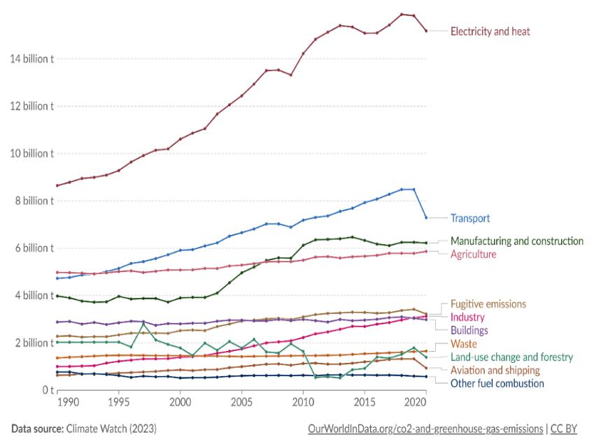
Figure1:GHGemissions(asper“OurWorldData”)[5]
Mostofthe produced oilis usedinthetransportationindustry. An electricvehicle addressesthe issuesofnot relyingon fuel supplies, being a zero-emission vehicle, and operating silently, which lowers noise and air pollution owing to its onboardenergystoragesystem[6]
Theprimaryenergystoragecomponentofanelectriccarisitsbatteries.Thesuccessofanelectricvehicleisdeterminedby its batteries. Rechargeable batteries provide power to the controller, which in turn powers the electric motor. The electric/currentprinciplegovernstheoperationofanelectricvehicleruns.Itpowersanelectricmotorwithabatterypack orabattery.Themotorthenrotatesthegearbox,whichturnsthewheelsusingthepower(voltage)fromthebatteries [7] Although Different types of batteries have been used in electric vehicles, lithium-ion (Li-ion) batteries show the greatest promiseandarecurrentlybeingused[8]
Table1:ComparisonofvariousbatterytypesusedinEVs[8]
Batteries face several key limitations. They struggle to meet peak power demands, which is a major drawback. Additionally, the frequent charge and discharge cycles required in applications needing instant power input and output negatively impact battery life. Thermal management also poses a challenge, making it difficult for batteries to operate safelyunderhigh-powerloads [9] Thisinvolves not onlywarmingthe batteryto coldtemperaturesto reachthedesired power limits but also cooling it down. Balancing the cells in a battery system is another problem that affects the battery life. The voltages of the individual cells eventually drifted apart in the absence of a balancing system. When a battery is usedforhigh-ratecharging anddischarging,thisconditionworsens [10] Ontheotherhand,supercapacitors (SC) havea long-life cycle, high specific capacitance, high power density, high power rates, and minimal maintenance requirements. Thefactthatsupercapacitorscanbechargedanddischargedquicklyisoneoftheirmainsellingpoints[11]
Inthisstudy,wewillstudythebatteryandsupercapacitor-basedhybridenergystoragesystem(HESS)combiningpower densitywithenergydensitytoofferthebestpossibleperformancesforElectricCarsbyusingMATLABsimulink.
International Research Journal of Engineering and Technology (IRJET) e-ISSN:2395-0056
Volume: 11 Issue: 07 | July 2024 www.irjet.net p-ISSN:2395-0072
The study also presents various HESS topologies and a MATLAB comparison between full-active and passive configurations.ItwasfoundthatFull-ActiveHESSdemonstratesbetterpowermanagementcomparedtoPassiveHESS,as FA-HESSgeneratesmorethan41%ofthepowerPassiveHESSgeneratesforthesameload.ItwasalsofoundthatFA-HESS wasapproximately2%moreefficientthanPassiveHESS,whichmakesitbetterforhigh-performanceapplications.
Inanenergystoragesystemwherebothsupercapacitorsandbatteriesareusedasasinglestoragesystem,wherewecan exploittheadvantagesofbatteriesandsupercapacitorsandmitigatetheirdisadvantages,wecallitahybridenergystorage system (HESS) It combines the benefits of multiple energy storage systems by combining high-energy-capacity devices with high-power-capability devices [12]. HESS’ s aim is to balance short-term power peaks with long-term energy requirements, with high-energy storage devices acting as the primary storage and high-power energy storage devices as thesecondarystorage[13]
ThevariousbenefitsofsharingpowerinaHESSareasfollows:
A higher power limit can be attained by incorporating an external power delivery device that surpasses the capacityofasingleenergy-storagedevice[12]
Thelifespanofabatterycanbeprolongedbyproducingalowerinstantaneouspoweroutput,whichconsequently ensures that the temperature of the battery remains within safe parameters, as the supercapacitor assumes responsibilityfordeliveringtherequiredpower[14].
The more effectively a battery is utilized by reducing the power or current drawn from it, the greater the efficiencywithwhichpowermaybeextractedfromit[14]
1.2.
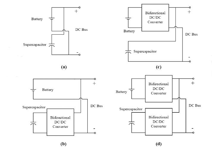
Generally, HESS topologies can be divided into three categories: passive, semi-active, and fully active topologies [15] In thepassiveHESStopologyshowninFig(3a), Supercapacitors(SCs)andbatteriesarearrangedinaparallelconfiguration andare directlyconnected totheload. Althoughthe topologyisstraightforwardandinexpensive, thecontributionof the SCs is small. A superconductor provides energy only when its terminal voltage changes. Consequently, when the SC is connectedinparalleltothebattery,itrestrictsvoltagefluctuations,therebylimitingitscontribution [16] TheSemi-active HESSenablestheDC/DCconvertertoregulateoneoftheenergystoragedevices,eitherthebatteryortheSCstack,while the other storage device remains linked to the load without any regulation. It is further divided into battery semi-active (bSA)HESSandcapacitorsemi-active(cSA)HESS.
IncSA HESS, a battery is combined with a supercapacitor, and then they arelinked to the load by a DC-DC converter Fig (3b). The system is regulated in a manner where the battery provides a relatively steady current, which is equivalent to theaverageloadcurrent,whilethesupercapacitorprovidesthefluctuatingportionoftheloadcurrent.Bypositioningthe DC-DC converter on the supercapacitor instead of the battery, the voltage of the ultracapacitor is separated from the voltageofthebatteryandtheload [17] InbSAHESS,thebatteryiscontrolledbyDC-DCconvertersFig(3c).SCsrespond quickly because they are directly linked to the motor drives. Regardless of the load profile, the battery’s current may be managedtomaintaintheSCchargeandallowforasmoothdischargeprofile,whichkeepsthebatterysafe[18]
Full-active HESS (FA-HESS) (Fig (3d)) solves the disadvantages of both semi-active HESSs. Both the battery and the supercapacitor are controlled by DC-DC converters, which are connected to the DC link, which is connected to the load. Thesupercapacitoreffectivelyutilizesitswholeoperatingvoltagerange,eliminatingtheneedforhigh-powerpulsesfrom the battery.Thisisachieved by efficientlymanaging its currentandcorrectlyadjustingtheDC-link voltagevia theuse of DC/DCconverters.Nevertheless,thesystemissomewhatintricate,anditseffectivenessisexpectedtobesubparduetothe transferofpowerviaDC/DCconverters[19].
International Research Journal of Engineering and Technology (IRJET) e-ISSN:2395-0056
Volume: 11 Issue: 07 | July 2024 www.irjet.net p-ISSN:2395-0072
MATLAB Simulink was used to simulate the full-active and passive HESS. Battery and supercapacitor models from Simscape were used to model the FA-HESS and Passive HESS, respectively. DC-DC converters for the fully active HESS weremodeledseparately,andacontrollerwasdesignedfortheFA-HESS,whichallowedustohavecompletecontrolover theFAhybridsystem.
TheparametersforthebatteryandsupercapacitorforbothFA-HESSandPassivewerekeptthesame,andtheyarelisted intables(2)and(3),respectively.
Table2:ParametersofBatteryinActiveandPassiveHESS
Parameters
Table3:ParametersofSupercapacitorforActiveandPassiveHESS
Parameters
International Research Journal of Engineering and Technology (IRJET) e-ISSN:2395-0056
2.1. Modelling of DC-DC converters:
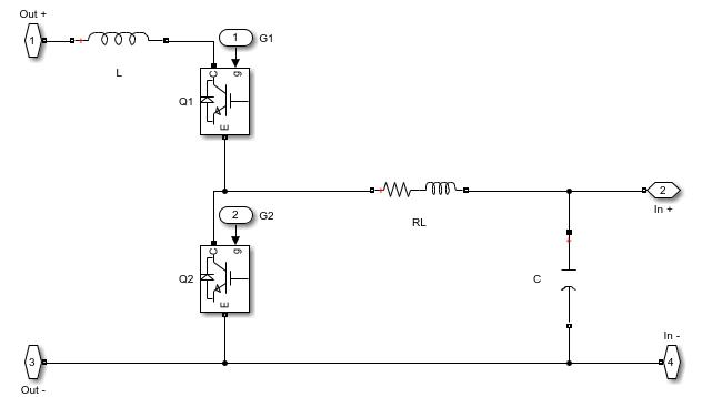
A DC-DC converter is a device that uses DC as an input and output. They use semiconductor devices as switches, and switchingoccursatveryhighfrequencies[21].Inourmodel,theswitchingfrequencywassetas15000KHz.
Fig (3) shows the MATLAB model of the boost DC-DC converter for supercapacitors and batteries. It comprises an inductor,capacitor,andIGBTswitch.
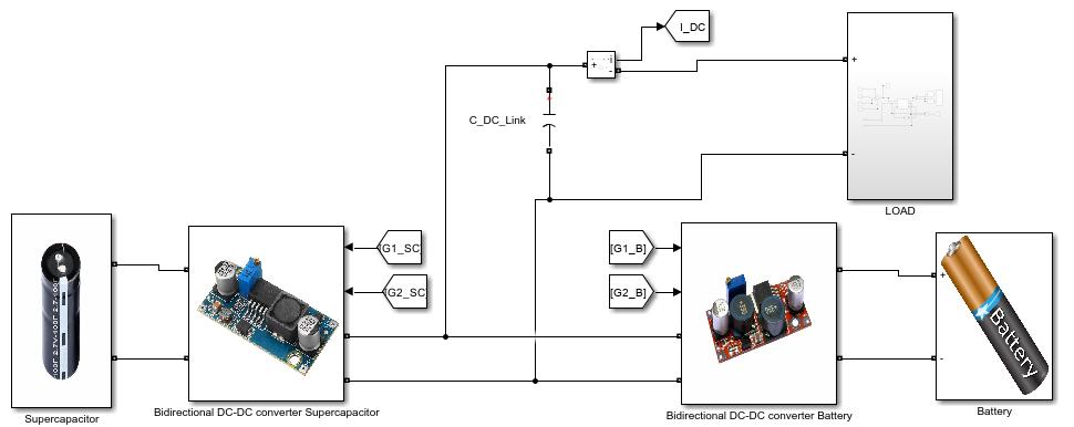
2 2. Modelling of the Full-Active HESS
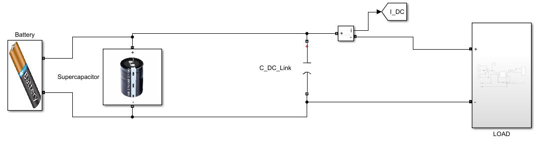
Fig (4) shows the MATLAB model of FA-HESS. As shown, the supercapacitor and battery have individual converters connectedtothem,whicharesubsequentlyconnectedtotheload
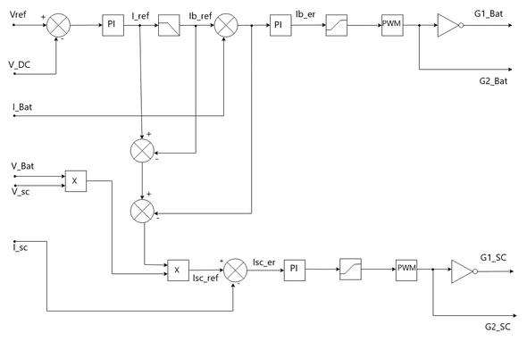
2.4. Modelling of the controller for FA-HESS
The figure (5) shows the controller used for FA-HESS. It’s based on the work by [22] For the battery, the actual voltage (V_DC)iscomparedwiththereferencevoltage(V_ref),andtheresultingerrorsignalisfedintothePIcontroller. Inorder toreducetheerror,thePIsignalgeneratestheI_refneededfromtheHESS Inordertoavoidhighcharge/dischargerates,a rate limiter is present in the controller. The rate limiter's output is sent to the battery converter as a reference current signal.Thisreferencecurrentisnowcomparedwiththebatterycurrent,andtheresultingerrorissenttothePIcontroller, whichgeneratesIb_er,anditisthensenttothePWMgenerator,whichgeneratespulsesforthebatteryconverterswitches (G1_Bat,G2_Bat).
Volume: 11 Issue: 07 | July 2024 www.irjet.net p-ISSN:2395-0072 © 2024, IRJET | Impact Factor value: 8.226 | ISO 9001:2008 Certified Journal | Page836
International Research Journal of Engineering and Technology (IRJET) e-ISSN:2395-0056
Volume: 11 Issue: 07 | July 2024 www.irjet.net p-ISSN:2395-0072
FortheSC,theprocessisthesame.Theonlydifferenceisthelackofaratelimitersinceitproduceshighcharge/discharge ratesforthesystem.G1_SCandG2_SCarethepulsesgeneratedbythePWMgenerator.
2.3. Modelling of the Passive HESS
Fig(6)showstheMATLABmodelofthepassiveHESS.Thebatteryandsupercapacitorwereconnectedtotheloadwithout anyconverters.
3. Experimental Studies
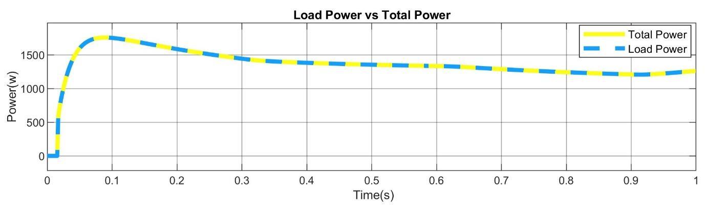
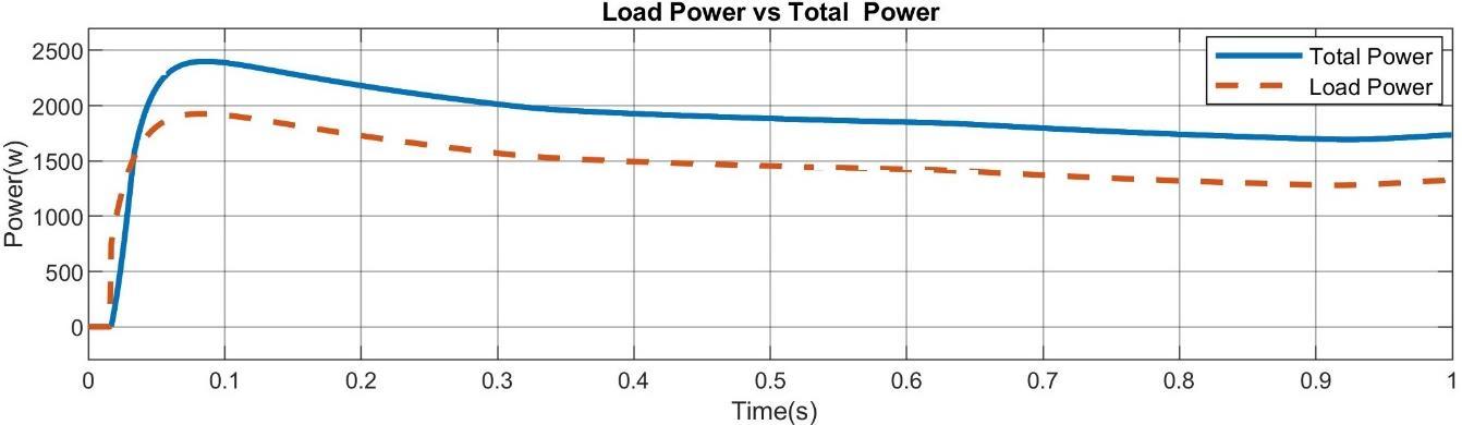
3.1. Power Comparison
Figure (7) shows us the graph of load power vs total power of the passive HESS system. The load power is almost the sameasthatofthetotalpowerbecausethereisadirectconnectionbetweenthebatteryandsupercapacitortotheloadas therearenoactivepowerelectronics(DC-DCconverter)inthecircuit,whichmeanstherearenoadditionalpowerlosses. Contrarytothis,inFA-HESS,thegraph (Figure 8) ofloadpowervstotalpowershowsthatthetotalpowerofthesystemis more than that of the load. One of the reasons for that is the DC-DC converters which control the power flow from the batteryandSCandsupplythattotheload.Wecomparedthegraphs,andwediscoveredthatthepassiveHESSgenerateda peakpowerof approximately 1700 watts,whiletheFA-HESSgenerateda peakpowerof approximately 2400 watts.This meansthateventhough therearesomepowerlossesassociatedwiththeFA-HESS,thepowerdissipatedbytheFA-HESS tothesystemisaround41%morethanthatofthepassiveHESS.
International Research Journal of Engineering and Technology (IRJET) e-ISSN:2395-0056
Volume: 11 Issue: 07 | July 2024 www.irjet.net p-ISSN:2395-0072
3.2. Efficiency Comparison
Tocalculatetheefficiencyoftheload(DCMachine),wefirstneedtocalculateitsinputpowerandoutputpower
3.2.1. Calculating the Input Power:
Forcalculatingtheinputpoweroftheload,weneedfirsttocalculatethepowerofthearmaturecircuitandthepower ofthefieldcircuit,andthenwehavetofindtheirsumasshowninequation(1).

(1)
Where Pin =InputPower, Par =Powerofthearmaturecircuit,and Pf =Powerofthefieldcircuit
Equations(2)and(3)showtheequationsforcalculatingPowerforthearmaturecircuitandthefieldcircuit
The power of the armature circuit can be calculated by:

Where Var =Voltageofarmaturecircuit,and Iar =Currentofarmaturecircuit
The power of Field circuit can be calculated by:

Where, Vf = Voltageoffieldcircuitand If = Currentoffieldcircuit
International Research Journal of Engineering and Technology (IRJET) e-ISSN:2395-0056
3.2.2. Calculating the Output Power
Outputpoweriscalculatedusingequation(4).

(4)
Where Pout=OutputPower, Ԏ =Torqueappliedonthemachine,and N =SpeedoftheDCMachine
3.2.2. Efficiency of the load (ƞ)
Theefficiencyoftheloadiscalculatedusingequation(5).

(5)
TheefficiencyofpassiveHESSandFA-HESSwascalculatedusingtheaboveequations,andwefoundthatpassiveHESShad a70.34%efficiencyandFA-HESShada72.52%efficiency.
4. Conclusion
Inthispaper,theeffectofsupercapacitorsandbatterycombinationsforenergystoragesystemswasstudied;weclaimed that it is prominent to use hybrid energy storage systems for electric vehicles. We have elucidated the operation of an electric vehicle and the necessity of combining supercapacitors with batteries to create a hybrid energy storage system (HES),asthissystemcouldoffera sustainablealternativetogasoline-poweredvehicles,whichsignificantlycontributeto greenhousegasemissions.Inelectricandhybridcars,thebatteryandsupercapacitor-basedHESScombinepowerdensity withenergydensitytoofferthebestpossibleperformance.
The paper also presents various HESS topologies, as well as a MATLAB comparison between full-active and passive configurations.ItwasfoundthatFull-ActiveHESSdemonstratesbetterpowermanagement comparedtoPassiveHESSas FA-HESSgeneratesmorethan41%ofthepowerPassiveHESSgeneratesforthesameload,anditwasalsofoundthatFAHESSwasapproximately2%moreefficientthanPassiveHESS,whichmakesitbetterforhigh-performanceapplications.
5. References
[1] M.-K. Tran et al., “A Review of Range Extenders in Battery Electric Vehicles: Current Progress and Future Perspectives,” WorldElectricVehicleJournal,vol.12,no.2,Art.no.2,Jun.2021,doi:10.3390/wevj12020054.
[2] “Topic: Transportation emissions worldwide,” Statista. Accessed: May 21, 2024. [Online]. Available: https://www.statista.com/topics/7476/transportation-emissions-worldwide/
[3] J. A. Sanguesa, V. Torres-Sanz, P. Garrido, F. J. Martinez, and J. M. Marquez-Barja, “A Review on Electric Vehicles: TechnologiesandChallenges,” SmartCities,vol.4,no.1,Art.no.1,Mar.2021,doi:10.3390/smartcities4010022.
[4] M. B. F. Ahsan, S. Mekhilef, T. K. Soon, M. B. Mubin, P. Shrivastava, and M. Seyedmahmoudian, “Lithium-ion battery and supercapacitor-based hybrid energy storage system for electric vehicle applications: A review,” International JournalofEnergyResearch,vol.46,no.14,pp.19826–19854,2022,doi:10.1002/er.8439.
[5] H. Ritchie, P. Rosado, and M. Roser, “CO₂ and Greenhouse Gas Emissions,” Our World in Data, Dec. 2023, Accessed: May21,2024.[Online].Available:https://ourworldindata.org/co2-and-greenhouse-gas-emissions
[6] K.Raut,A.Shendge,J.Chaudhari,andR.Lamba,“EnergyStorageTechnologiesforHybridElectricVehicles,”in 2022 IEEE International Conference on Power Electronics, Drives and Energy Systems (PEDES), Dec. 2022, pp. 1–4. doi: 10.1109/PEDES56012.2022.10080184.
[7] “ReviewonElectricVehicle,” International Journal For Science Technology And Engineering,vol.10,no.1,pp.1667–1670,Jan.2022,doi:10.22214/ijraset.2022.40095.
Volume: 11 Issue: 07 | July 2024 www.irjet.net p-ISSN:2395-0072 © 2024, IRJET | Impact Factor value: 8.226 | ISO 9001:2008 Certified Journal | Page839
International Research Journal of Engineering and Technology (IRJET) e-ISSN:2395-0056
Volume: 11 Issue: 07 | July 2024 www.irjet.net p-ISSN:2395-0072
[8] L. Kouchachvili, W. Yaïci, and E. Entchev, “Hybrid battery/supercapacitor energy storage system for the electric vehicles,” JournalofPower Sources,vol.374,pp.237–248,Jan.2018,doi:10.1016/j.jpowsour.2017.11.040.
[9] J.CaoandA.Emadi,“ANewBattery/UltraCapacitorHybridEnergyStorageSystemforElectric,Hybrid,andPlug-In Hybrid Electric Vehicles,” IEEE Transactions on Power Electronics, vol. 27, no. 1, pp. 122–132, Jan. 2012, doi: 10.1109/TPEL.2011.2151206.
[10] J.Cao,N.Schofield,andA.Emadi,“Batterybalancingmethods:Acomprehensivereview,”in 2008 IEEE Vehicle Power andPropulsionConference,Sep.2008,pp.1–6.doi:10.1109/VPPC.2008.4677669.
[11] M.S.Halper,“Supercapacitors:ABriefOverview,”2006.
[12] Z.Dong et al.,“ASurveyofBattery–SupercapacitorHybridEnergyStorageSystems:Concept,Topology,Control and Application,” Symmetry,vol.14,no.6,Art.no.6,Jun.2022,doi:10.3390/sym14061085.
[13] F. Ibanez, “Hybrid Energy Storage Systems in Electric Vehicle Applications,” in Electric Vehicles - Design, Modelling andSimulation,IntechOpen,2023.doi:10.5772/intechopen.113000.
[14] M.Reveles-Miranda,V.Ramirez-Rivera,andD.Pacheco-Catalán,“Hybridenergystorage:Features,applications,and ancillary benefits,” Renewable and Sustainable Energy Reviews, vol. 192, p. 114196, Mar. 2024, doi: 10.1016/j.rser.2023.114196.
[15] M.AlTakrouri,S.MdAyob,N.R.NikIdris,M.J.A.Aziz,R.Ayop,andM.F.B.M.Said,“ComparativeAnalysisofPassive andSemi-activeHybridEnergyStorage System Topologiesfor Electric Vehicle,” in 2023 IEEE Conference on Energy Conversion(CENCON),Oct.2023,pp.75–80.doi:10.1109/CENCON58932.2023.10369822.
[16] T.Wilberforce,A.Anser,J.A.Swamy,andR.Opoku,“Aninvestigationintohybridenergystoragesystemcontroland power distribution for hybrid electric vehicles,” Energy, vol. 279, p. 127804, Sep. 2023, doi: 10.1016/j.energy.2023.127804.
[17] C. Lerman, A. Horosov, and A. Kuperman, “Capacitor semi-active battery-ultracapacitor hybrid energy source,” in 2012 IEEE 27th Convention of Electrical and Electronics Engineers in Israel, Nov. 2012, pp. 1–4. doi: 10.1109/EEEI.2012.6377027.
[18] R. Powade and Y. Bhateshvar, “Design of semi-actively controlled battery-supercapacitor hybrid energy storage system,” MaterialsToday:Proceedings,vol.72,pp.1503–1509,Jan.2023,doi:10.1016/j.matpr.2022.09.378.
[19] S.Peresada,Y.Nikonenko,andS.Kovbasa,“Voltage-CurrentControlinFullyActiveHybridEnergyStorageSystems,” in 2023 IEEE 4th KhPI Week on Advanced Technology (KhPIWeek), Oct. 2023, pp. 1–6. doi: 10.1109/KhPIWeek61412.2023.10312949.
[20] E. Wang, F. Yang, and M. Ouyang, “A Hybrid Energy Storage System for a Coaxial Power-Split Hybrid Powertrain,” 2017.doi:10.5772/67756.
[21] M.BiswalandS.Sabyasachi,“AstudyonrecentDC-DCconverters,” InternationalJournalof EngineeringResearch and Applications(IJERA),vol.2,no.6,pp.657–663,2012.
[22] S.K.Kollimalla,M.K.Mishra,A.Ukil,andH.B.Gooi,“DCGridVoltageRegulationUsingNewHESSControlStrategy,” IEEETransactions onSustainableEnergy,vol.8,no.2,pp.772–781,Apr.2017,doi:10.1109/TSTE.2016.2619759.
2024, IRJET | Impact Factor value: 8.226 | ISO 9001:2008