
International Research Journal of Engineering and Technology (IRJET) e-ISSN: 2395-0056
Volume: 11 Issue: 07 | July 2024 www.irjet.net p-ISSN: 2395-0072

International Research Journal of Engineering and Technology (IRJET) e-ISSN: 2395-0056
Volume: 11 Issue: 07 | July 2024 www.irjet.net p-ISSN: 2395-0072
Rudra Umesh Kolwalkar1 , Hassanali Virani2
1Student, Dept. of Electronics and Telecommunication Engineering, Goa College of Engineering, Goa, India
2Professor, Dept. of Electronics and Telecommunication Engineering, Goa College of Engineering, Goa, India
Abstract – This paper proposes a microstrip antenna of inverted L stubs and a semi-circle shaped patch with the help of a metamaterial planar structure, i.e. a complementary split ring resonator (CSRR) in the 3-6 GHz frequency range using a High Frequency Structure Simulator (HFSS) for wireless applications. The presence of metamaterial on the ground plane improves the antenna parameters. The antenna has dimensions of 60 mm x 45 mm designed on a 1.6 mm thick FR4 substrate with microstrip line feeding. It has a CSRR ring of 4 mm etched on the ground plane. It resonates at frequencies of 3.54 (3.39 3.76) GHz and 5 (4.62-5.65) GHz with a bandwidth of 370 MHz and 700 MHz and a return loss of –14.2023 dB and –34.7791 dB, respectively. The antenna has an average gain of 1.89 dBi. It can be used for C Band, WiMAX, Wi-Fi, and WLAN applications. The antenna’s performance was analyzed in terms of return loss, VSWR, bandwidth, radiation pattern, gain and radiation efficiency.
Key Words: Microstrip antenna, Metamaterial, CSRR, InvertedLStubs,Cband,WiMAX,Wi-Fi,WLAN.
Microstrip patch antennas are popular for wireless communication applications like mobile and satellite due to their light weight, low profile, ease of fabrication and feed[1].Theuseofa thick dielectricsubstrate witha low dielectric constant is preferred for good antenna performance since it provides better efficiency [2] Microstrip patch antennas can be in any arbitrary shape, suchasatriangularpatchantenna[3].
Metamaterial is an artificial material that has a negative dielectricconstant.Thesematerialsareperiodicwhichare not found in nature. It has negative dielectric permittivity (ε) and negative magnetic permeability (µ) [4]. Complementarysplitringresonators(CSRR)andsplitring resonators (SRR) are widely used as metamaterial elements.ASwastikslottedhexagonalpatchantennawith metamaterial based complementary split-ring resonators is proposed. The unit cell structure of the CSRR metamaterial antenna has been optimized to enhance the antenna’s performance in terms of bandwidth, resonant frequency,gain,andminiaturization[5].Adual-feedCSRRloaded multiband microstrip patch antenna with a single
layer dielectric constant for ITS and other wireless applicationsisreported[6]
Acompacttri-bandantenna basedoninverted-Lstubsfor smart devices was designed with three inverted L stubs and a triangular shaped monopole antenna. The longest stub portion is printed on the substrate’s back and connected to the other portion via a metallic pin. The antennaresonatesatmultibandfrequenciesof2.4GHz,3.5 GHzand5.5GHz[7]
Inthispaper,amicrostripantennaofinvertedLstubsand a semi-circle shaped patch with a metamaterial planar structure complementary split ring resonator (CSRR) on the ground plane is designed. The proposed antenna exhibitsdualfrequenciesat3.54GHzand5GHzinthe3-6 GHz frequency range. The resonant frequency is tuned by changing the stub length and CSRR position. It is applicable for WiMAX, C band (n77, n78, n79) and Wi-Fi applications.
The complementary split ring resonator (CSRR) is one of themostfamousmetamaterialstructures.Itiscomposedof twoconcentricmetallicringswithslitsetchedineachring onitsoppositeside.Thegapbetweentheringsrestrictsthe current flow around the rings, which considerably increases the resonance frequency of the structure. The resonant frequency can be easily tuned by changing the positionandgeometryparametersoftheCSRR[8]
CSRR can be represented as an L-C circuit. The resonance frequencyofCSRRcanbecalculated[9]usingEquation(1).
International Research Journal of Engineering and Technology (IRJET) e-ISSN: 2395-0056
Volume: 11 Issue: 07 | July 2024 www.irjet.net p-ISSN: 2395-0072
Where L = 11 mm is the average length, N = 2 is the number of CSRR rings, w = 2 mm is the width of metallic rings, d =4mmisthedistancebetweentheslots, K(k) isthe first order complete elliptical integral, ε0 is vacuum permittivity, µ0 is vacuum permeability and ρ is the filling ratio. Hence the inductance LCSRR = 5.0403x10⁻⁸ Henry and the capacitance CCSRR = 2.2797x10⁻¹⁴ Farad. Therefore, the resonancefrequencyis fr =4.6951GHz.
CSRR is placed in the waveguide setup as shown in Fig. 1. The scattering parameters S11 and S21 of this unit cell are extracted using the appropriate boundary conditions specified.Thewaveguide’sleftandrightfacesaresettothe perfect magnetic conductor (PMC) boundary condition. Thewaveguide’stopandbottomfacesaresettotheperfect electricconductor(PEC)boundarycondition.Portsareset at the sides of the waveguide. The negative permittivity and negative permeabilityof theCSRR are extractedusing the retrieved scattering parameters S11 and S21 using the NicolsonRossWeir(NRW)equation[10] ( ) ( )
where V1 = S21 – S11, V2 = S21+ S11, k0=wavenumberoffree spaceand d =substratethickness.
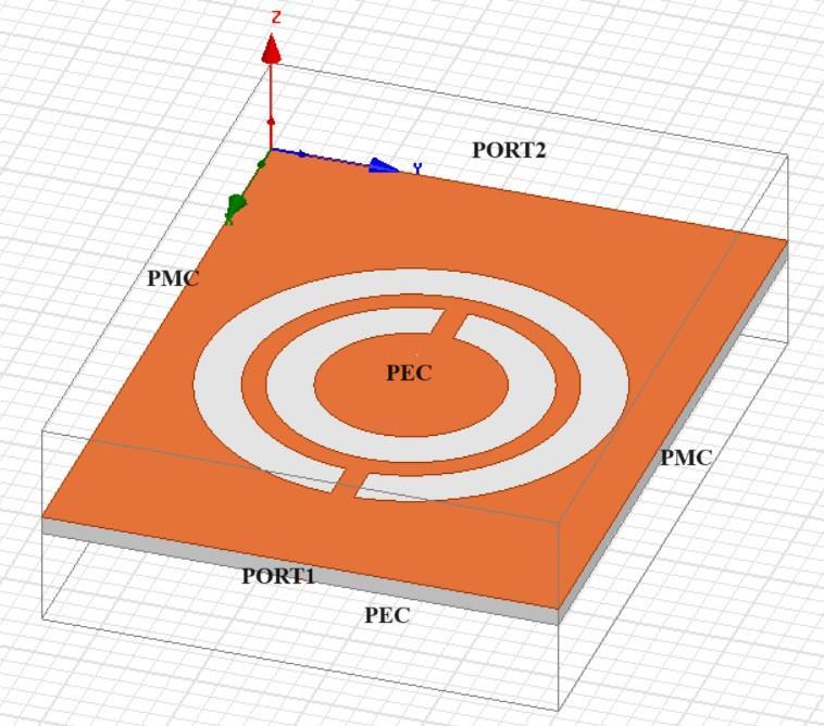
-1:SparameterextractionsetupoftheproposedCSRR
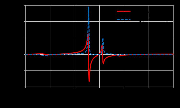
Fig. 2 shows the negative permittivity of the proposed CSRR at 4.46 GHz and other resonant frequencies. The negative permeability of the proposed CSRR is shown in Fig. 3 at 4.58 GHz and other resonant frequencies. The proposed metamaterial structure, CSRR is etched on the ground plane. The proposed CSRR produces negative permittivityandnegativepermeability,whicharethemain featuresofmetamaterial.
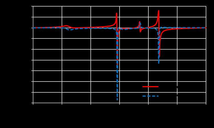
-3:NegativePermeabilityoftheProposed
3.
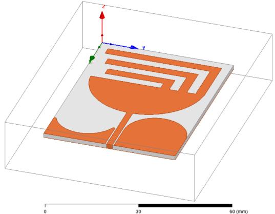
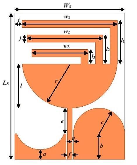
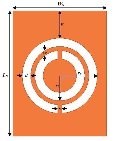
The design of the proposed inverted L stubs and semicircle shaped microstrip patch antenna with CSRR on the ground plane using High Frequency Structure Simulator (HFSS)softwareispresentedinthissection.Theproposed antennahasdimensionsof60x45mm2 designedonaflame retardant(FR-4)substrateof1.6mmthickwithadielectric constantof4.4andhasmicrostriplinefeeding.TheCSRRof 4 mm is etched on the ground plane. Table I displays the dimensions of the proposed antenna. The Trimetric view, front view and bottom view of the proposed antenna are showninFig.4(a),(b)and(c),respectively.
Volume: 11 Issue: 07 | July 2024 www.irjet.net
-4:Proposedantennadesign(a)Trimetricview(b) Frontview(c)Bottomview
Table -1: DimensionsofProposedAntennaDesign
The simulated analysis of the proposed antenna is done using HFSS software in the 3-6 GHz frequency range. The proposed antenna resonates at two frequencies 3.54 GHz and 5 GHz, with a bandwidth of 370 MHz at (3.39-3.76) GHzand700MHzat(4.64-5.65)GHz.Itwasobservedthat when you vary the size of the stubs and the curves, the frequencybandsshift.ThepresenceofCSRRontheground plane gives a better response compared to the ground plane.
Fig. 5 shows the return loss (S11) of –14.2023 dB and –34.7791 dB at 3.54 GHz and 5 GHz, respectively. Fig. 6 shows the voltage standing wave ratio (VSWR) plot with values of 1.4843 and 1.0372, which are near one and less than2.ThevaluesofreturnlossandVSWRarementioned inTableII.
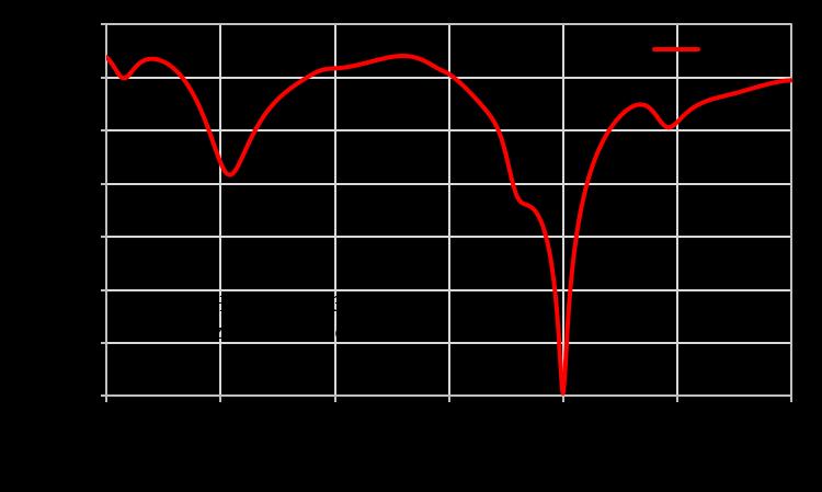
Fig -5:ReturnLoss(S11)
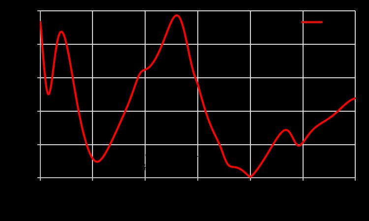
Fig -6:VSWR
Table -2: SimulationResults
International Research Journal of Engineering and Technology (IRJET) e-ISSN: 2395-0056
Volume: 11 Issue: 07 | July 2024 www.irjet.net p-ISSN: 2395-0072
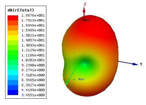
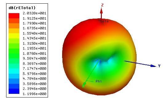
Fig.7(a)and(b)showthe3Dradiationpatternat3.54GHz and5GHz,respectively.
The2DradiationpatternintheEplanewithphi=0andthe Hplanewithphi=90oftheproposedantennaat3.54GHz and 5GHzisshown inFig.8 (a)and(b),respectively. The E-field and H-field patterns are described as Omni directionalinnature,sothisdualbandantennaisradiated inalldirections.
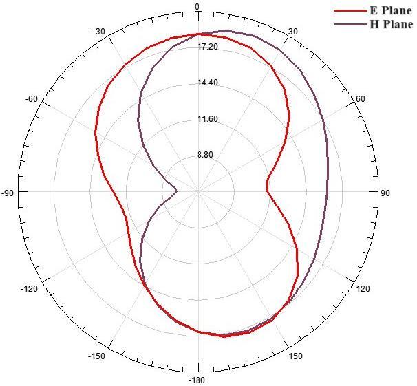
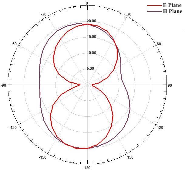
-8:2DRadiationPatternintheEandHPlaneat(a) 3.54GHzand(b)5GHz
The3DgainplotoftheproposedantennaisshowninFig.9 (a) and (b) at 3.54 GHz and 5 GHz. It has a gain of 1.2367 dBi at 3.54 GHz and 2.5471 dBi at 5 GHz. The proposed antennahasanaveragegainof1.89dBi.Ithasadirectivity of 2.2932 dBi and 3.7754 dBi at 3.54 GHz and 5 GHz, respectively.

-9:3DGainPlotat(a)3.54GHzand(b)5GHz
International Research Journal of Engineering and Technology (IRJET) e-ISSN: 2395-0056
Volume: 11 Issue: 07 | July 2024 www.irjet.net p-ISSN: 2395-0072
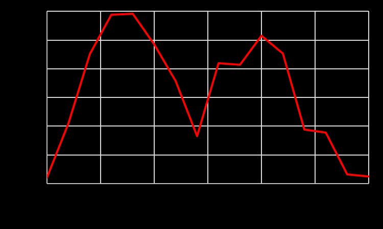
The proposed antenna’s radiation efficiency was found. The radiation efficiency of 78 % is obtained at 3.54 GHz and75%at5GHz.Fig.10showstheradiationefficiencyof theproposedantenna.
5.
A microstripantenna of inverted L stubsanda semi-circle shapedpatchwiththemetamaterialplanarstructureCSRR onthegroundplane,havingdimensionsof60x45x1.6mm3 which operates in 3-6 GHz frequency range is proposed and designed in this paper. It resonates at frequencies of 3.54 GHz and 5 GHz having bandwidths of 370 MHz and 700 MHz with a return loss of –14.2023 dB and –34.7791 dBrespectively.IthasaVSWRof1.4843and1.0372,which islessthan2andanaveragegainof1.89dBi.Thisantenna canbeusedforapplicationssuchasCband,WiMAX,Wi-Fi andWLAN.
[1] W. Ali, E. Hamad, M. Bassiuny and M. Hamdallah, "Complementary split ring resonator based triple band microstrip antenna for WLAN/WiMAX applications," Radioengineering, vol. 26, no. 1, pp. 7884,April2017.
[2] G. Bhai, M. Dubey and L. K. Tyagi, "A New Design of Dual-Band Microstrip Patch Antenna for Wireless Communication," International Research Journal of Engineering and Technology (IRJET), vol. 4, no. 6, pp. 3000-3003,June2017.
[3] B. L. Narayana and S. N. Bhavanam, "Design & Simulation of Triple Frequency Triangular Patch Antenna byUsingHFSS14.0,"International Journalof Applied Engineering Research, vol. 10, no. 20, pp. 18585-18589,April2015.
[4] G. Vidhate, "Metamaterial loaded rectangular patch antenna for wireless communication application," InternationalJournal, vol.9,no.3,pp.193-197,March 2021.
[5] K. L. Kishore, R. R. Reddy and N. K. Darimireddy, "Swastik Slotted Hexagonal Patch Antenna with Metamaterial Based Complementary Split-Ring Resonator," ICTACT journal on microelectronics, vol. 6,no.03,pp.995-1000,October2020.
[6] G. Upadhyay, N. Kishore, S. Raj, S. Tripathi and V. S. Tripathi, "Dual‐feed CSRR‐loaded switchable multiband microstrip patch antenna for ITS applications," IET Microwaves, Antennas & Propagation, vol.12,no.14,pp.2135-2140,November 2018.
[7] N.Hussain,A.Abbas,S.M.Park,S.G.ParkandN.Kim, "A compact tri-band Antenna based on inverted-L stubs for smart devices," Computers, Materials & Continua, vol.70,no.2,pp.3321-3331,January2022.
[8] A. T. Devapriya, G. Rani and S. Robinson, "Dual resonant microstrip patch antenna using metamaterialplanarstructuresforSbandandCband applications," ICTACT Journal on Communication Technology, vol. 7, no. 4, pp. 1432-1437, December 2016.
[9] R. S. Daniel and R. Selvaraj, "A low-profile spilt ring monopole antenna loaded with hexagonal split ring resonator for RFID applications," Progress In Electromagnetics Research M, vol. 92, pp. 169-179, May2020.
[10] S. P. J. Christydass and N. Gunavathi, "Dual-band complementary split-ring resonator engraved rectangularmonopoleforGSMandWLAN/WiMAX/5G sub-6 GHz band (new radio band)," Progress In Electromagnetics Research C, vol. 113, pp. 251-263, July2021.