
International Research Journal of Engineering and Technology (IRJET) e-ISSN:2395-0056
Volume: 11 Issue: 07 | July 2024 www.irjet.net p-ISSN:2395-0072

International Research Journal of Engineering and Technology (IRJET) e-ISSN:2395-0056
Volume: 11 Issue: 07 | July 2024 www.irjet.net p-ISSN:2395-0072
Ravi Dave1,2, Indravadan B. Dave3* , Jay J. Vora4*, Subhash Das5 , Sonam Patel2
1Research Scholar, Gujarat Technological University, Ahmedabad, India
2Metallurgy Engineering Department, Dr. S. and S. S. Ghandhy College of Engineering and Technology, Surat, India.
3Metallurgy Engineering Department, Government Engineering College, Sector 28, Gandhinagar, India
4Mechanical Engineering Department, Pandit Deendayal Energy University, Gandhinagar, India, 5ITW India Private Limited, Vadodara, India --
Abstract:
Thisstudyaimstosystematicallyinvestigateandcomparetheeffectsofkeyweldingparametersonweldbeadcharacteristics inregulatedmetaldeposition(RMD)andflux-coredarcwelding(FCAW)processeswhenappliedtobead-on-plateweldingon 316LNstainlesssteel.Thisresearchfocusesonunderstandingtherelationshipsbetweenweldingparameterssuchascurrent, voltage, and heat input and weld bead dimensions such as bead width, height, depth of penetration, and width of the heataffected zone for both techniques. The overall quality of the welds produced by each technique is examined through visual inspection,liquidpenetranttesting,andmacroscopicandmicroscopicexaminations.Throughthiscomparativeanalysisof the RMDandFCAWprocesses,thisresearchaimstoprovidevaluableinsightsintotheselectionofweldingparametersfor316LN stainlesssteel,therebyimprovingweldqualityandefficiencyinindustrialapplications.TheresultsindicatethatinbothRMD andFCAW, ahighercurrentincreasesbeaddimensionsandpenetration, whereasa highervoltageproduceswiderbeadsbut reducesheightandpenetration.InFCAW,thehigherheatinputproducesawiderHAZthanRMDdoes
Keywords: regulated metal deposition (RMD) technique, flux cored arc welding (FCAW), 316LN, bead-on plate trials, governingvariables,weldbeaddimensions
1. Introduction:
Stainless steels enriched with nitrogen possess a special combination of properties that make them ideal in various industries where strength, corrosion resistance, and high-temperature mechanical performance are crucial. The use of these materials as cost-effective alternatives to other materials further enhances their value in engineering and manufacturing applications [1, 2]. 316LN is a variant of low-carbon austenitic stainless steel that plays an important role as an essential structuralcomponentinvarioussectors,includingchemicalprocessing,transportation,storage,andnuclearindustries,owing to its advantageous high-temperature mechanical properties, compatibility with liquid sodium, good weldability, good irradiation resistance, and adequate experience in the use of these materials in sodium-cooled reactors [3–5]. The 316LN material demonstrates favorable plasticity and relatively high impact toughness, particularly under cryogenic conditions. In thecontextofjoiningthesestructuralmaterials,arcweldingis thepreferredtechniquebecauseofitscompatibilitywiththeir properties[6,7]
SMAW and TIG welding are commonly used for the initial root pass in a weld joint. However, these methods have certain limitations, including time-consuming procedures and inconsistent weld characteristics [8, 9]. On the other hand, GMAW,whichissuitablefor filling,faceschallengesin therootpass becauseof issuessuchasspatter formation [10].Inthis context, the introduction of a modified short-circuiting process represents an exciting opportunity to increase the efficiency andeffectivenessofroot-passwelding[11,12]
RegulatedMetalDeposition(RMD),introducedbyMillerElectricin2004,isanadvancedshort-circuitingarcwelding processthat involvesmanaging weldingduring eachshort-circuitphaseandadjustingthewaveformon thebasis of material properties [13, 14]. Precisely regulated metal transfer ensures the consistent deposition of droplets, greatly simplifying the
International Research Journal of Engineering and Technology (IRJET) e-ISSN:2395-0056
Volume: 11 Issue: 07 | July 2024 www.irjet.net p-ISSN:2395-0072
welder's ability to manage the molten puddle [15]. A thorough grasp of the controlled short-circuit mechanism is gained by segmenting a standard RMD cycle into seven distinct phases, as outlined by Das et al. [16]. Compared with TIG and MIG welding,thisprocessofferssignificantadvantages,suchasafasterweldingspeed(6–12inchesperminute),resultinginthree timesfasterproductionandreducedrework.TheRMDprocessallowsforarootpassdepthof3.2to6.4mm,eliminatingthe needforhotpassesand increasingtheweldingefficiency [17].Italsominimizesheatinput,reducingmaterial distortionand the risk of issues such as cold laps and spatter. These benefits lead to superior weld quality and increased productivity [18, 19].DinBandhuetal.comparedRMDandGMAWonASTMA387-11-2steelplates.TheyreportedthatRMDproduceddeeper penetration,asmallerheat-affectedzone,andlowerhardnessacrossallweldmentzones thandidGMAW[20].DinBandhuet al.studiedtheeffectsofmetal-coredfillerwireonRMD-weldedlow-alloysteelplates.Theas-weldedplatespresentedtypical dendriticsurfaces,whereastheheat-treatedplatespresentedfiner,irregularmartensiticstructuresintheweldzone[21]
Flux-CoredArcWelding(FCAW)usesflux-filledtubularwiretoshieldtheweldpoolandpreventcontamination. This is unique because it contains flux within the continuous wire electrode, which improves the number of operator duty cycles [22] Compared with shielded metal arc welding (SMAW), FCAW provides higher deposition efficiency and faster deposition rates for austenitic stainless steels, and it offers better penetration. This process is widely adopted by industries to increase welding productivity. Recently, there has been a notable increase in the utilization of FCAW because of its numerous advantages. These include its efficiency in effectively depositing weld metal, compatibility with automation, adaptability to various welding positions, user-friendliness relative to alternative methods, capacity to produce high-quality welding seams, and cost-effectiveness when joining thick materials [23]. A study by Ronaldo R. De Paz investigated how 43 companies worldwide use FCAW. Research has shown that FCAW is still widely used because it is easy to work with. Companies rated FCAW products highly for quality and performance, both domestically (4.6) and abroad (4.33) [24]. Amit Kumar compared FCAW and MIG welding for repairing damaged low-Cr-Mo alloy steel boiler tubes. FCAW-welded samples presented higher tensile and yield strengths than MIG-welded samples did [25]. Several studies have examined the effects of welding parameters on bead geometry in various welding processes. Shoeb et al. [26] and I.S. Kim et al. [27] reported that higher currents increased the penetration depth and bead width in the MIG and GMAW processes, respectively. Both studies noted that higher voltages resulted in wider beads. P.K. Palani et al. [28] observed an increased penetration area with increasing current when flux-cored wire was used on structural steel. Similarly, Memduh Kurtulmus et al. [29] reported that a higher current increased the reinforcement height and penetration depth in flux-cored arc welding, whereas a higher voltage widenedthebead.DebKumarAdaketal. [30]foundthatagreaterheatinputincreasedtheHAZwidthintheGMAWofmild steel.These findingsconsistentlydemonstratethesignificantinfluence of the weldingparameterson the beadgeometryand weldcharacteristicsacrossdifferentmaterialsandweldingtechniques.
The literature available in the public domain extensively covers welding techniques such as submerged arc welding (SAW),gastungstenarcwelding(GTAW),andgasmetalarcwelding(GMAW)andexaminesweldingperformanceparameters suchasthe heat-affectedzone, penetration depth, and weld beadgeometry[31–35].However,there is a noticeableresearch gapinthecontextofadvancedGMAWprocesses,particularlythoserelatedtomodifiedshort-circuitmetaltransfer,asseenin the RMD technique. This unexplored area holds promise for further investigation. With limited research papers available on theRMDtechnique,itisnoteworthythatthismethodremainslargelyunexploredforweldingstainlesssteelsofgrade316LN, as observed from literature surveys. Therefore, its application in this context represents a novelty. Additionally, the FCAW processisgaining widespreadacceptanceamongindustries;therehasbeennopreviouscomparisonbetweentheFCAWand RMD processes. This comparison is anticipated to produce intriguing results and simplify process selection. In the present study, bead-on-plate trials were conducted on 316LN base metal via two distinct methods: the Regulated Metal Deposition (RMD) technique with 316 L solid wire and the Flux Cored Arc Welding (FCAW) technique with 316 L flux-cored wire. The objective of this research is to aesthetically evaluate and compare bead-on-plate welding deposited by two distinct welding processes:RMDandFCAW.Thiswork aimstoassesstheinfluenceofvariables suchas current,voltage,andheatinputrates on various welding performance characteristics, such as the heat-affected zone, depth of penetration, bead width, and bead height.
International Research Journal of Engineering and Technology (IRJET) e-ISSN:2395-0056
Volume: 11 Issue: 07 | July 2024 www.irjet.net p-ISSN:2395-0072
2.1.
Inthiswork,austeniticstainlesssteel(316LN)wasselectedasthebasemetal.Twodifferentfillerwireswereusedforthe experiments,namely,AWSA5.9:ER316LsolidwirefortheRMDtechniqueandAWSA5.22:E316LT1-4flux-coredwireforthe FCAWtechnique.Bothfillerwireshaveadiameterof1.2mm.Thechemicalcompositionsandmechanicalpropertiesofthese filler wires and the base metal are outlined in Tables 1 and 2, respectively. The initial plate, with a thickness of 40 mm, was precisionmachinedintosamplesmeasuring8mm×200mm×750mmviaawire-cutEDMmachine.Separate sampleswere preparedforboththeRMDandFCAWtrials.
Table 1 –Chemicalcompositionofthefillerwireandbasemetala .
a Takenfromactualtestcertificates.
Table 2 –Mechanicalpropertiesofthefillerwireandbasemetala
a Takenfromactualtestcertificates.
2.2. Welding Trials
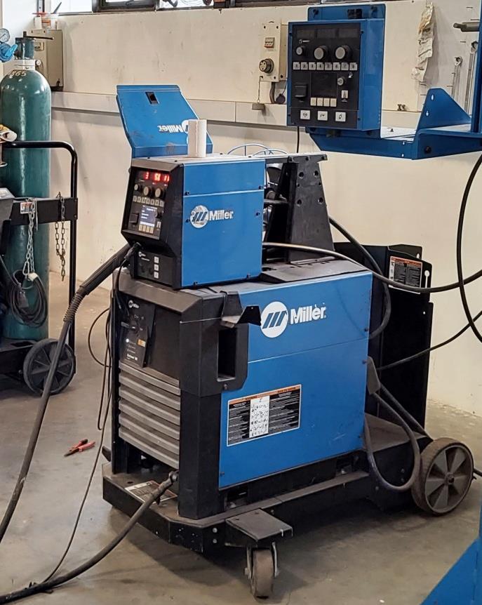
A Miller Pipe Worx 400 machine was employed for both the RMD and FCAW processes. This machine is a multiprocess machinethatincludesconventional stick,DCTIG, flux-cored,and MIG weldingprocesses.ItalsofeaturesadvancedRMDand pulsedMIGprocesses.ThemachineisshowninFigure1.
International Research Journal of Engineering and Technology (IRJET) e-ISSN:2395-0056
Volume: 11 Issue: 07 | July 2024 www.irjet.net p-ISSN:2395-0072

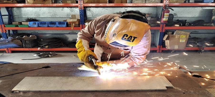
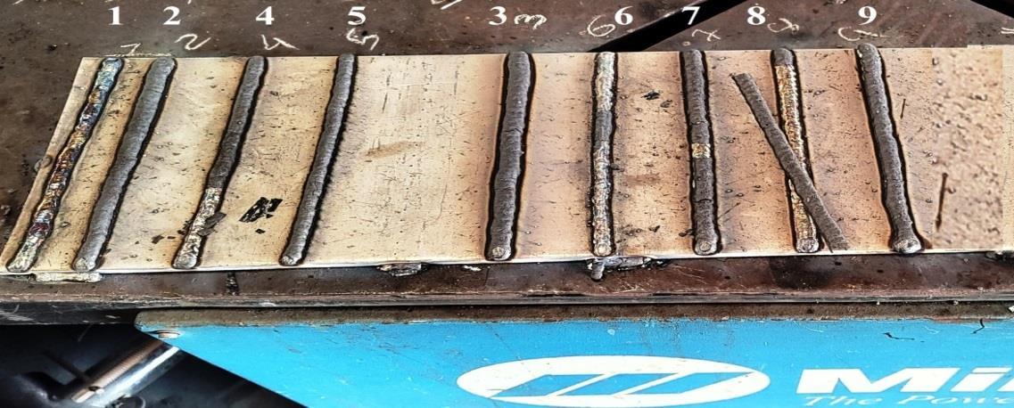
FollowingASMESectionIX,acertifiedwelderperformedmanualweldinginthe1Gposition.Forahigh-qualityweld, the selection of welding parameters such as current, voltage, and gas flow rate is essential. These parameters were chosen after consulting industry experts and consumable suppliers, as well as reviewing the relevant literature. To confirm the weldingsettingson thebasisof weldbeadprofiles,bead-on-platetestingwascarriedout,combiningestablishedapproaches with adaptive adjustments for accuracy [31–35]. A total of eighteen bead-on-plate trials were carried out using FCAW and RMD techniques. While the RMD trials employed a gas mixture of 98% argon (Ar) and 2% oxygen (O2), the FCAW studies utilized 80% argon (Ar) and 20% carbon dioxide (CO2). The experiments were conducted on 750 × 200 × 8 mm plates. The platesetupandbead-on-plateweldingprocedureareshowninFigures3and4,respectively.Tables2and3providespecific weldingparametersfortheRMDandFCAW.

International Research Journal of Engineering and Technology (IRJET) e-ISSN:2395-0056
Volume: 11 Issue: 07 | July 2024 www.irjet.net p-ISSN:2395-0072
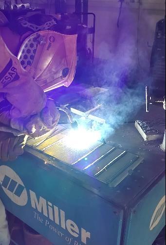

3 Originalphotographofbead-on-platewelding
Table 3 –WeldingParameterforRMDtechnique.
International Research Journal of Engineering and Technology (IRJET) e-ISSN:2395-0056
Volume: 11 Issue: 07 | July 2024 www.irjet.net p-ISSN:2395-0072
Table 4 –WeldingParametersforFCAWtechnique.
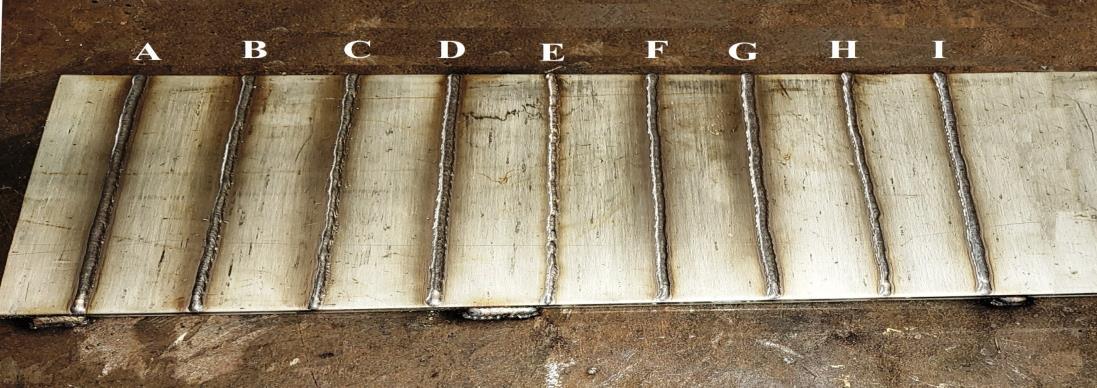
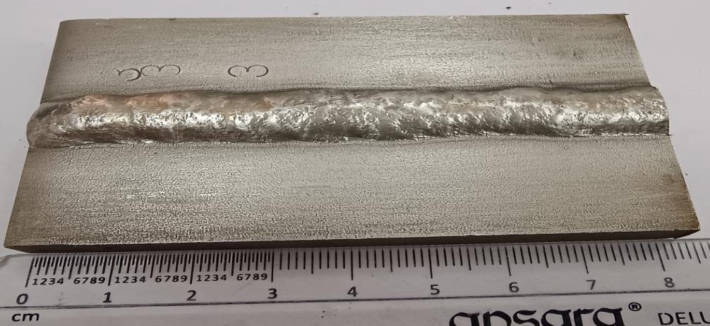
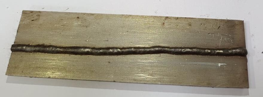
Thebead-on-platetrialsdepositedbytheRMDtechniqueandFCAWtechniquearerepresentedinFigures4and5.


Visual inspection is widely regarded as the most prevalent and cost-effective approach for assessing weld quality. This methodinvolvesusingtheunaidedhumaneyetodetectanysurfaceirregularitiespresentwithintheweldarea. Thisapproach offers immediate detection of welding flaws, thereby reducing subsequent repair expenses resulting from detected
International Research Journal of Engineering and Technology (IRJET) e-ISSN:2395-0056
Volume: 11 Issue: 07 | July 2024 www.irjet.net p-ISSN:2395-0072
imperfections in the weld region. For bead-on-plate welding, this method was used for identifying surface defects such as spatter, porosity, undercut, etc. [20]. Initially, visual inspection was carried out on both the RMD and FCAW bead-on-plate weldedsamplesfollowingameticulouscleaningprocessusingastainlesssteelwirebrush.
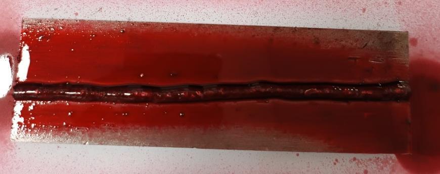
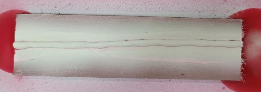
Theliquidpenetrantinspectiontechniqueisareliableapproach foridentifyingdiscontinuitiespresentonthesurfacesof impermeable metals and other similar materials. Common types of flaws that can be successfully detected via this approach includecracks,seams,laps,coldshuts,laminations,andporosity.Liquidpenetranttestingwasconductedonall thebead-onplatetrials.
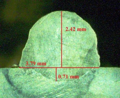
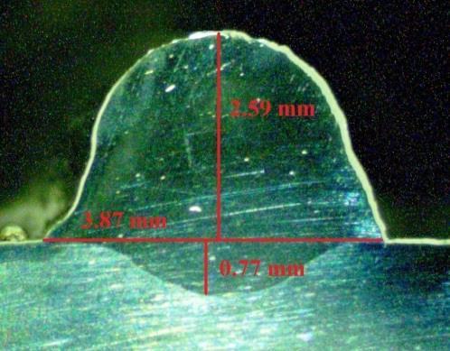
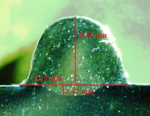
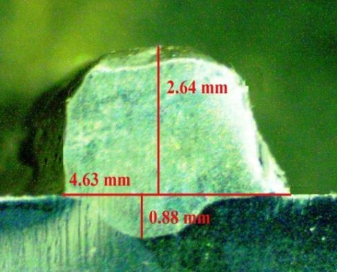
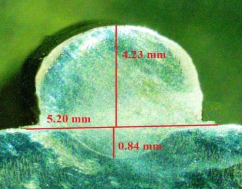
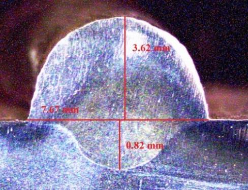
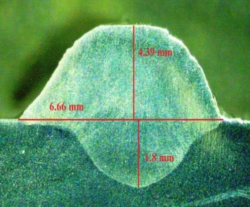
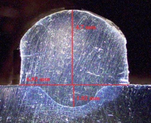
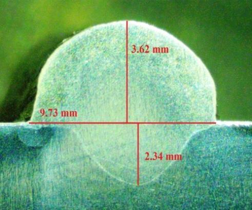
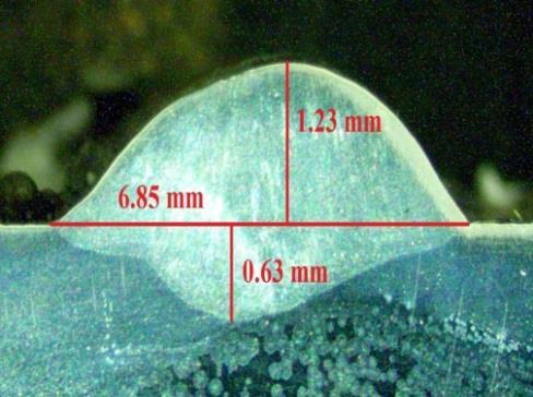
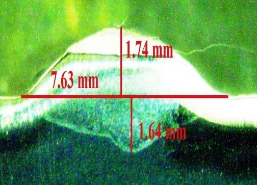
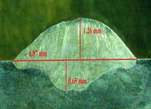
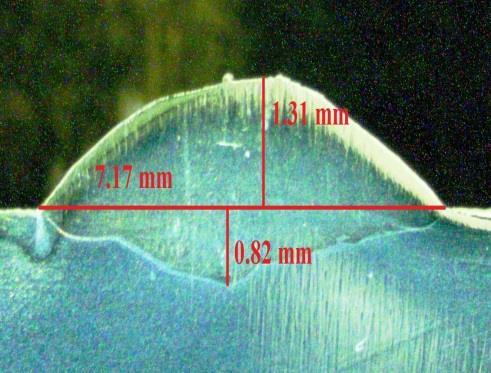
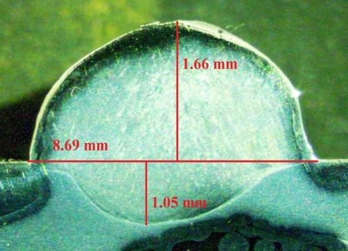
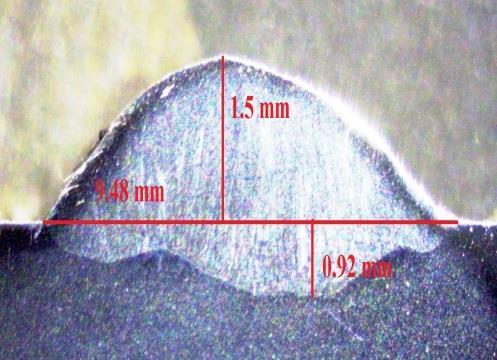
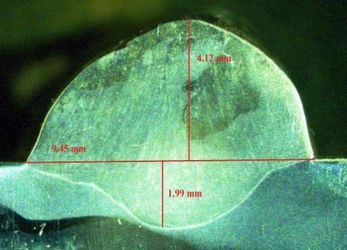
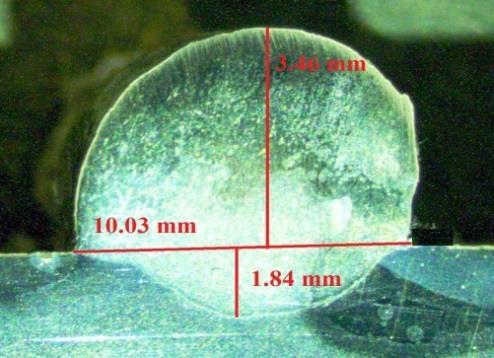
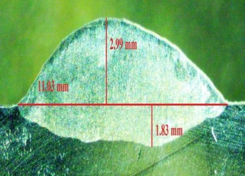
To investigate the macrostructural characteristics of the bead-on plate welds, bead-on welded plates were sectioned transversely from the central portion of the weld length using a band-saw machine. All the samples underwent a routine polishing process involving the use of SiC abrasives, followed by disc polishing to achieve a mirror-finished surface. For etching,asolutionofaquaregia(comprising15mlofHCland5mlofHNO3)wasused.Theetchedsamplesweresubsequently examinedunderamacroscopetomeasuretherequiredresponses,suchasdepthofpenetration(DOP),beadwidth(BW),and bead height (BH), as shown in Figures 12 and 13. The heat-affected zone (HAZ) was not discernible through a macroscope. Consequently,tomeasurethewidthoftheHAZprecisely,amicroscopicanalysiswas performed.Apreparedmirror-polished sample underwent an etching process and was subsequently subjected to examination using a metallurgical microscope, as showninFigure14.
Theheatinputrepresentstheenergytransferredtotheweldduringwelding andistypicallymeasuredastheenergyper unitlengthoftheweld(e.g.,kJ/inorkJ/mm).Belowistheformulausedtocalculatetheheatinput[36] (1)
where:
Q=Heatinput(kJ/inorkJ/mm),V=Voltage(volts)
I=Current(amps),S=Travelspeed(inchesperminuteormillimetersperminute)
The heat input in welding processes is consistently of great interest, given its influence on the morphology of the weld bead,fusionzone,andmicrostructuresintheheat-affectedzone(HAZ),aswellasthemechanicalbehavioroftheweldedjoint [37]. Cortéz et al. [38], in their examination of the impact of heat input on the microstructure and mechanical properties of welded joints, employed the welding energy equation. This equation, derived as the product of the mean current and mean voltage divided by the travel speed, is referred to as heat input. The calculated heat inputs for both the RMD and FCAW processesareshowninTables7and8.
3. Results and discussion:
3.1. Visual inspection:
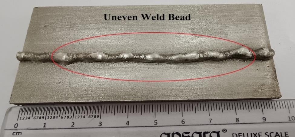
DuringthevisualexaminationofRMDbead-on-platesamples,theexaminationofSampleA,depictedinFigure6,revealed aweldbeadcharacterizedbyaslenderwidthandanunevenshape.
International Research Journal of Engineering and Technology (IRJET) e-ISSN:2395-0056
Volume: 11 Issue: 07 | July 2024 www.irjet.net p-ISSN:2395-0072


International Research Journal of Engineering and Technology (IRJET) e-ISSN:2395-0056
Volume: 11 Issue: 07 | July 2024 www.irjet.net p-ISSN:2395-0072

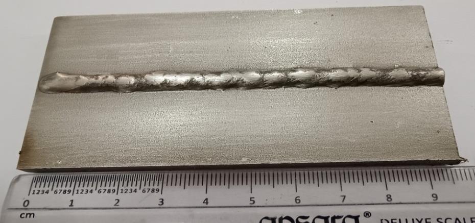
Thisresultcanbetracedbacktotheapplicationoflowcurrentandvoltagesettings,specificallyan80-amperecurrentand a 12-voltvoltage. On the otherhand,visual inspection oftheremainingsamplesconfirmedthevisual clarity of the weld and theabsenceofanydiscernibledefects,suchassurfaceporosityandunderfill.Moreover,thedepositionoffillermetaldisplayed a flawless and uniform distribution throughout the entire length of the weld bead. For visual reference, see Figure 7, illustratingthevisualinspectionofSampleD,whichdemonstratesfreedomfromsurfacedefects.
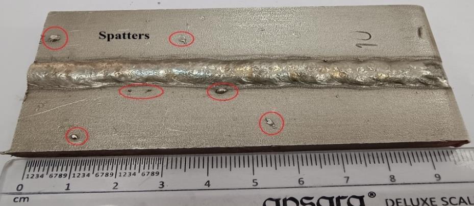
Inthevisualexaminationof theFCAWbead-on-platesamples,theanalysisofSample10,illustratedinFigure8, revealed the presence of spatter. This occurrence is attributed to the application of a high welding current of 220 amperes. However, visualexaminationoftheremainingsamplesconfirmedthevisualclarityoftheweldsintheabsenceofanydiscernibledefects. Forvisualreference,seeFigure9,whichdepictsthevisualinspectionofSample3andshowsfreedomfromsurfacedefects.
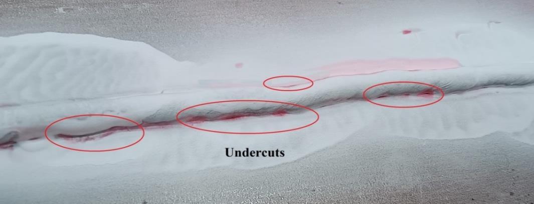
TheliquidpenetranttestingofRMDbead-on-plateweldedSampleH,asshowninFigure10,revealsanundercutinSampleH, asfurtherindicatedinFigure11.Thisphenomenonmaybeattributedtotheapplicationofahigherweldingcurrent.However, duringliquidpenetranttestingoftheremainingRMDandFCAWsamples,theexceptionalqualityoftheweldswasconfirmed. Importantly,inspectionrevealedtheabsenceofanysurfacedefects.
International Research Journal of Engineering and Technology (IRJET) e-ISSN:2395-0056
Volume: 11 Issue: 07 | July 2024 www.irjet.net p-ISSN:2395-0072

The dimensions derived from the macroscopic observations are presented in Tables 7 and 8. The macroscopic images capturingthebead-on-plateweldsforboththeRMDandFCAWprocessesareillustratedinFigures12and13,respectively.
International Research Journal of Engineering and Technology (IRJET) e-ISSN:2395-0056
Volume: 11 Issue: 07 | July 2024 www.irjet.net p-ISSN:2395-0072


Volume: 11 Issue: 07 | July 2024 www.irjet.net


International Research Journal of Engineering and Technology (IRJET) e-ISSN:2395-0056
Volume: 11 Issue: 07 | July 2024 www.irjet.net p-ISSN:2395-0072
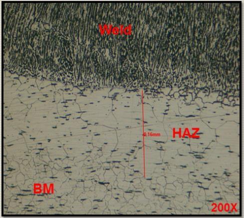
Figure 14 MicroscopicanalysisforthemeasurementofthewidthoftheHAZ
Microscopic analysis was conducted to measure the width of HAZ for both RMD and FCAW bead-on-plate samples. The weld bead geometry details for the RMD and FCAW bead-on-plate samples are documented in Tables 5 and 6, respectively.
Table 5 –DetailofWeldbeadgeometryforRMDbeadonplatesamples
Table 6 –DetailofWeldbeadgeometryforFCAWbeadonplatesamples Sample
e-ISSN:2395-0056 Volume: 11 Issue: 07 | July 2024 www.irjet.net p-ISSN:2395-0072
3.4. Effect of the welding current:
Theimpactoftheweldingcurrentonthebeadwidth,depthofpenetration,andbeadheightatavoltageof15voltsin the RMD welding technique is presented in Figure 15. Figure 16 shows the corresponding effects of the FCAW welding techniqueatavoltageof22volts.AsshowninFigure16,fortheRMDtechnique,anincreaseintheweldingcurrentcorrelates withanincreasein the weldbeadheight, width, and depth of penetration. Similarly,asindicated in Figure16, for the FCAW technique, an increase in the welding current results in increased weld bead height, depth of penetration, and weld bead width. These observations may be attributed to the increase in the welding current, which increases the melting rate of the fillerwire.This,inturn,leadstomoremoltenmetalbeingdeposited,contributingtoanincreaseinbeadheight[39] Ahigher welding current also results in an increase in the droplet temperature, causing smaller droplets to form more frequently. Additionally, the increased temperature enhances the falling velocity of the droplets, and their momentum influences the penetrationdepth.Consequently,higherweldingcurrentscontributetoachievingadeeperweldbead.Moreover,theelevated currentincreasestheheatinput,enlargingthemelting volumeoftheworkpieceandsubsequentlyincreasingthebeadwidth [40]
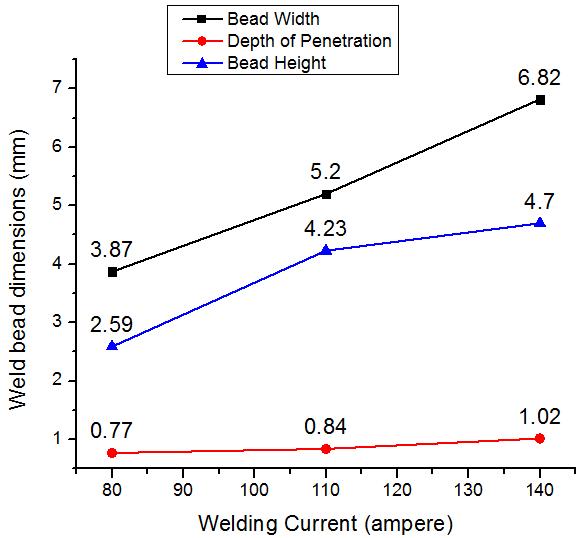
Figure 15 EffectoftheweldingcurrentontheBW,DOP,andBHintheRMDtechnique
International Research Journal of Engineering and Technology (IRJET) e-ISSN:2395-0056
Volume: 11 Issue: 07 | July 2024 www.irjet.net p-ISSN:2395-0072
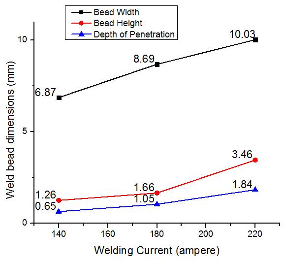
Figure 16 EffectoftheweldingcurrentontheBW,DOP,andBHintheFCAWtechnique
3.5. Effect of voltage:
The influence of voltage on bead width, depth of penetration, and bead height at a current of 110 amperes in the RMD welding technique is shown in Figure 17. In contrast, Figure 18 illustrates the effect of voltage on these parameters at a current of 180 amperes in the FCAW welding technique. Figure 17, which illustrates the RMD technique, clearly shows that increasing the voltage leads to an expansion in bead width, accompanied by a reduction in both bead height and depth of penetration. Similarly, as shown in Figure 18, for the FCAW technique, an increase in voltage leads to an increase in bead width,whereasthebeadheightanddepthofpenetrationdecrease.Theseeffectsmaybeattributedtothefactthatanincrease in the arc voltage results in higher heat input during welding. The bottom diameter of the arc expands with increasing arc voltage, leading to increased heating and melting at the workpiece surface [41, 42]. Consequently, a wider weld bead is obtained at a higher arc voltage. Notably, the increased arc voltage does not affect the droplet formation frequency, droplet temperature,dropletfallingvelocity,ormomentumofthedroplets[40].Asaresult,thepenetrationdepthofthewelddoesnot increase with increasing voltage. The decrease in weld bead height can be attributed to the simultaneous increase in bead widthandthereductionintheelectrodedepositareawithincreasingarcvoltage[42]
International Research Journal of Engineering and Technology (IRJET) e-ISSN:2395-0056
Volume: 11 Issue: 07 | July 2024 www.irjet.net p-ISSN:2395-0072
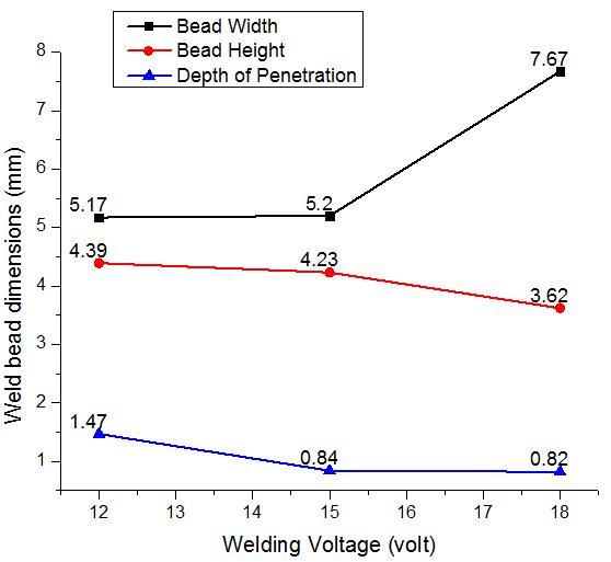
17 EffectofvoltageonBW,DOP,andBHintheRMDtechnique
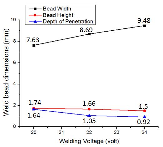
Figure 18 EffectofvoltageontheBW,DOP,andBHintheFCAWtechnique
2395-0056
Volume: 11 Issue: 07 | July 2024 www.irjet.net p-ISSN:2395-0072
AsdepictedinTables7and8,thebead-on-platetrialsfortheRMDtechnique,specificallytrialsEandG,andthebead-onplate trials for the FCAW process, namely, trials 1 and 2, exhibit nearly identical heat inputs of approximately 0.36 KJ/mm. UponcomparingtheweldbeadgeometriesoftheseRMDandFCAWbead-on-platetrials,thedatafromTables5 and6reveal that,underthesespecifiedconditions,theFCAWtechniqueresultsinagreaterweldbeadwidththantheRMDtechniquedoes. ThisdifferencecanbeattributedtothehighervoltageutilizedintheFCAWprocessthanintheRMDtechnique,astheelevated voltage in the FCAW tends to broaden the weld bead [40]. Conversely, the bead height is more pronounced in the RMD technique than in the FCAW technique. This disparity arises from the use of a solid wire in the RMD technique, which facilitates a higher deposition rate than the flux-cored wire does [43]. Additionally, the root run deposited by the RMD techniqueexhibitedaflatprofilewithnoapparentconvexityorconcavity,anditwasthickerthantraditionalGMAWroot[16]. Moreover,theFCAWprocessyieldsashallowerdepthofpenetration thantheRMDtechniquedoes.Thisobservationmaybe attributedtotheinfluenceofthearcvoltageonthearclength,whereadecreaseinthearclengthleadstoanarrowerarccone andamorefocusedarc.ThisphenomenonresultsingreaterdepthofpenetrationintheRMDtechnique[32].
International Research Journal of Engineering and Technology (IRJET) e-ISSN:2395-0056
Volume: 11 Issue: 07 | July 2024 www.irjet.net p-ISSN:2395-0072
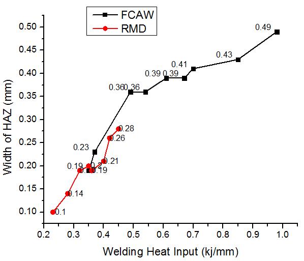
Figure 19 EffectoftheweldingheatinputonthewidthoftheHAZfortheRMDandFCAWtechniques
Figure19illustratestheinfluenceoftheweldingheatinputonthewidthoftheheat-affectedzone(HAZ)forboththeRMD and FCAW techniques. As depicted in Figure 20, there is a positive correlation between the increase in heat input and the wideningofHAZ.Thisrelationshipmaybeanticipatedbecauseastheheatinput increases,moreenergybecomesavailableto impact the microstructure of the material adjacent to the weld, resulting in a broader HAZ. [44]. Figure 21 also presents a comparisonofheatinputbetweentheRMDandFCAWweldingtechniques,revealingthattheFCAWprocess resultsinhigher heatinputthandoestheRMDtechnique.AmongalleighteenexperimentsinvolvingRMDandFCAWbead-on-platetrials,four exhibitnearlyidentical heatinputlevels.Specifically,experimentEandexperiment1bothdemonstratesimilar heatinputof 0.35 kJ/mm, whereas experiment G and experiment 2 almost match the heat input values of 0.36 kJ/mm and 0.37 kJ/mm, respectively. Comparing these trials, which share the same heat input, in terms of bead width, bead height, depth of penetration,andwidthoftheHAZ,yieldsintriguinginsights.
International Research Journal of Engineering and Technology (IRJET) e-ISSN:2395-0056
Volume: 11 Issue: 07 | July 2024 www.irjet.net p-ISSN:2395-0072
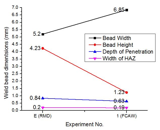
Figure 20 ComparisonofweldbeaddimensionsbetweenExperimentEandExperiment1
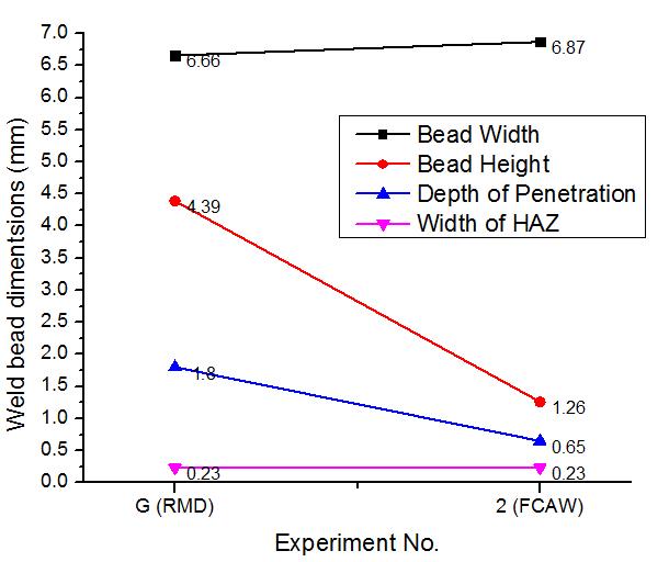
Figure 21 ComparisonofweldbeaddimensionsbetweenExperimentsGand2
Figure 21 shows a comparison of the weld bead dimensions between experiment E and experiment 1. At the same heat input of 0.35 kJ/mm, the width of the heat-affected zone is similar, and the depth of penetration is greater in experiment E thaninexperiment1.However,thebeadwidthisgreaterinexperiment1,whichwasdepositedbytheFCAWprocess,thanin experiment E, which was deposited by the RMD process. Conversely, the bead height is greater in experiment E, which was deposited by the RMD process, than in experiment 1, which was deposited by the FCAW process. Similarly, Figure 22
© 2024, IRJET | Impact Factor value: 8.226 | ISO 9001:2008 Certified Journal | Page1014
International Research Journal of Engineering and Technology (IRJET) e-ISSN:2395-0056
Volume: 11 Issue: 07 | July 2024 www.irjet.net p-ISSN:2395-0072
representsthecomparisonofweldbeaddimensionsbetweenexperimentGandexperiment2,whichalmostmatchheatinput values of 0.36 kJ/mm and 0.37 kJ/mm, respectively. The same trends observed in Figure 20 are evident in Figure 21. In the FCAW process, the wider bead width is due to the flux-cored wire's higher deposition rate than that of the solid wire. Moreover,FCAW'soperationathighervoltagesettingsbroadensthearc,leadingtoincreasedbeadwidthcomparedwithRMD [45–47]. Conversely, the RMD operates at lower voltage settings, contributing to narrower and taller bead heights. RMD technologyallowsprecisecontrolovermetaltransferanddepositionrates,maintaininghigherbeadheightswhilefinetuning the arc to deposit more metal onto the workpiece without compromising bead quality. While the higher voltage in FCAW broadensthearcandincreasesthebeadwidth,itmayresultinslightlyshallowerpenetrationthanRMDdoes[16,48,49].
The present work uses RMD and FCAW welding procedures to investigate welded 316LN samples via bead-on-plate techniques. It evaluates the impact of current, voltage, and heat input on weld parameters such as bead height, width, penetrationdepth,and heat affectedzone (HAZ)width. Visual inspectionreveals various characteristics:at 80A inRMD, the weldedbeadsareunevenandnarrow,whereasat220AinFCAW,spatteroccurs.Undercutsresultfromhighercurrentsinthe RMD.Despiteachievingfullpenetration,theRMDmethodresultsinagreaterbeadheightandpenetrationdepthbutnarrower bead and HAZ widths than the FCAW method does, which results in wider beads and HAZ but lower bead height and penetration.Inbothprocedures,thebeadheight,width,andpenetrationareimprovedby increasingtheweldingcurrent.An increasedvoltageintheRMDlengthensthebeadbutshortensitsheightandpenetration, similartotheFCAW.Theheatinput increases the HAZ width, with the FCAW showing a wider HAZ due to its higher heat. At equivalent heat inputs, the RMD resultsingreaterpenetrationandbeadheight,whereastheFCAWresultsinawiderbeadwidth.
References
1. Kumar DH, Reddy a. S (2013) Study of Mechanical Behavior in Austenitic Stainless Steel 316 Ln Welded Joints. Int J MechEngRobotRes2:1–22
2. VasantharajaP,VasudevanM,MaduraimuthuV(2018)EffectofArcWeldingProcessesontheWeldAttributesofType 316LNStainlessSteelWeldjoint.TransIndianInstMet71:127–137.https://doi.org/10.1007/s12666-017-1162-2
3. Fan Y, Wang K, Wang XY, et al (2021) Microstructures and mechanical properties of the fusion zone of 316L-316LN stainless steel multi-pass gas tungsten arc welded joint. J Mater Sci 56:17306–17318. https://doi.org/10.1007/s10853-021-06387-y
4. Patel NP, Badheka VJ, Vora JJ, Upadhyay GH (2019) Effect of Oxide Fluxes in Activated TIG Welding of Stainless Steel 316LN to Low Activation Ferritic / Martensitic Steel ( LAFM ) Dissimilar Combination. Trans Indian Inst Met. https://doi.org/10.1007/s12666-019-01752-7
5. SireeshaM,AlbertSK,ShankarV,SundaresanS(2000)Comparativeevaluationofweldingconsumablesfordissimilar welds between 316LN austenitic stainless steel and Alloy 800. J Nucl Mater 279:65–76. https://doi.org/10.1016/S0022-3115(99)00275-5
6. Awale DD, Ballal AR, Thawre MM (2020) Dissimilar weld joints of P91 and 316LN for power plants Applications-A review.MaterTodayProc28:2505–2510.https://doi.org/10.1016/j.matpr.2020.05.003
7. WenkaiX,LiZ,FujuZ,etal(2015)Effectofheatinputoncryogenictoughnessof316LNausteniticstainlesssteelNGMAGweldingjointswithlargethickness.MaterDes86:160–167.https://doi.org/10.1016/j.matdes.2015.07.115
8. Vasudevan M (2017) Effect of A-TIG Welding Process on the Weld Attributes of Type 304LN and 316LN Stainless Steels.JMaterEngPerform26:1325–1336.https://doi.org/10.1007/s11665-017-2517-x
9. MohandasT,ReddyGM,NaveedM(1999)Acomparativeevaluationofgastungstenandshieldedmetalarcweldsofa ``ferritic’’stainlesssteel.94:133–140
International Research Journal of Engineering and Technology (IRJET) e-ISSN:2395-0056
10 Singaravelu DL, Rajamurugan G, Devakumaran K (2018) Modified Short Arc Gas Metal Arc Welding Process for Root PassWeldingApplications.MaterTodayProc5:7828–7835.https://doi.org/10.1016/j.matpr.2017.11.463
11. DasS,VoraJJ,PatelV,etal(2021)Experimentalinvestigationonweldingof2.25Cr-1.0Mosteelwithregulatedmetal deposition and GMAW technique incorporating metal-cored wires. J Mater Res Technol 15:1007–1016. https://doi.org/10.1016/j.jmrt.2021.08.081
12. CuhelJ(2008)ModifiedGMAWforRootPasses.TPJ-TubePipeJournal®-Fabr1–4
13. RothM(2009)ShinnMechanicalUsesPipeWorxWeldingSystemtoIncreasePipeFabricationQualityandProductivity. MillElectrMfgLLC1–4
14. DepoM,DepoM,RmdT,etal(2020)WeldingSoftwareovercomesshortcircuitMIGlimitations.gabd.1–4
15. RyanJ(2018)MechanicalContractorDiversifiesandRedefinesBusinesstoMeettheDemandoftheMid-AtlanticSteel, OilandGasIndustries.MillElectrMfgLLC1–4
16. DasS,Vora JJ,Patel V(2019)RegulatedMetalDeposition(RMDTM)TechniqueforWeldingApplications:AnAdvanced GasMetalArcWeldingProcess.AdvWeldTechnolProcessDev23–32.https://doi.org/10.1201/9781351234825-2
17. Demenin MF (2023) Root Welding Using the Regulated Metal Deposition Technology (Review). Power Technol Eng 57:123–128.https://doi.org/10.1007/s10749-023-01632-7
18. J.B(1956)ByrneJ.Mechanicalcontractorincreasespipeweldingproductivityupto500%.2018.p.1–8.1–8
19. Roth M (2009) Graham Corporation Meets Reduced Rework Objectives With Help from Miller’s PipeWorxTM Welding Systems.MillElectrMfgLLC1–4
20. BandhuD,GoudEV,VoraJJ,etal(2023)InfluenceofRegulatedMetalDepositionandGasMetalArcWeldingonASTM A387-11–2 Steel Plates: As-deposited Inspection, Microstructure, and Mechanical Properties. J Mater Eng Perform 32:1025–1038.https://doi.org/10.1007/s11665-022-07185-6
21. Bandhu D, Djavanroodi F, Shaikshavali G, et al (2022) Effect of Metal-Cored Filler Wire on Surface Morphology and Micro-Hardness of Regulated Metal Deposition Welded ASTM A387-Gr.11-Cl.2 Steel Plates. Materials (Basel) 15:. https://doi.org/10.3390/ma15196661
22. Katherasan D, Sathiya P, Raja A (2013) Shielding gas effects on flux cored arc welding of AISI 316L ( N ) austenitic stainlesssteeljoints.MaterDes45:43–51.https://doi.org/10.1016/j.matdes.2012.09.012
23. Lathabai,S.,&StoutRD(1985)“Shieldinggasandheatinputeffectsonfluxcoredweldmetalproperties.”Weldjournal, 64(11),303s-313s64:303–313
24. De Paz, Ronaldo R., Gabriel P. Famadico, Allysa Mariel J. Ortiz, Raymund Carlo F. Tanap, Reylina Garcia Tayactac, Edward B. Ang, Ricky D. Umali and JH (2023) Analysison the industrial applications of flux cored arc welding on an internationalscale.4thIntConfMechIntellManufTechnol(ICMIMT),pp135-142IEEE,2023
25. AmitKumar,VijayakumarP(2023)ComparisonofWeldBuilt-upbyFCAWandMIGWeldingonDamagedLowCr-Mo AlloySteelTubeinBoilerApplication.IntJSciResArch8:492–505.https://doi.org/10.30574/ijsra.2023.8.2.0243
26. ParvezM,KumariP(2017)EFFECTOFMIGWELDINGINPUTPROCESSPARAMETERSONWELD
27. KimIS,KwonWH,ParkCE(1996)TheeffectsofweldingprocessparametersonweldbeadwidthinGMAWprocesses. J.KWS14:204–213
28. Palani PK, Murugan N (2007) Optimization of weld bead geometry for stainless steel claddings deposited by FCAW. 190:291–299.https://doi.org/10.1016/j.jmatprotec.2007.02.035
Volume: 11 Issue: 07 | July 2024 www.irjet.net p-ISSN:2395-0072 © 2024, IRJET | Impact Factor value: 8.226 |
International Research Journal of Engineering and Technology (IRJET) e-ISSN:2395-0056
Volume: 11 Issue: 07 | July 2024 www.irjet.net p-ISSN:2395-0072
29. Kurtulmus M, Bilici MK, Catalgol Z (2015) EFFECTS OF WELDING CURRENT AND ARC VOLTAGE ON FCAW WELD BEADGEOMETRY.23–28
30. KumarD,ManidiptoA(2015)DevelopmentofaDirectCorrelationofBeadGeometry,GrainSizeandHAZWidthwith theGMAWProcessParametersonBead-on-plateWeldsofMildSteel.https://doi.org/10.1007/s12666-015-0518-8
31. DasS,VoraJ,PatelV,BogumS(2021)Experiencewithadvancedweldingtechniques(RMD&P-GMAW)withseamless metal cored wire for Oil & Gas pipeline industries. J Phys Conf Ser 1950:. https://doi.org/10.1088/17426596/1950/1/012043
32. Prajapati V, Dinbandhu, Vora JJ, et al (2020) Study of parametric influence and welding performance optimization during regulated metal deposition (RMDTM) using grey integrated with fuzzy taguchi approach. J Manuf Process 54:286–300.https://doi.org/10.1016/j.jmapro.2020.03.017
33. Bandhu D, Abhishek K (2021) Assessment of weld bead geometry in modified shortcircuiting gas metal arc welding processforlowalloysteel.MaterManufProcess36:1384–1402.https://doi.org/10.1080/10426914.2021.1906897
34. WeldingAMMIG,ParametersCMIGWelding :SettingtheCorrectParameters.1–6
35. ConrardyC(2018)GuidelinesForGasMetalArcWelding.MillElectrMfgLLC1–17
36. Anon(1980)StructuralWeldingCode-Steel.AmNatlStandInstitute,Stand
37. Quintino L, Liskevich O, Vilarinho L, Scotti A (2013) Heat input in full penetration welds in gas metal arc welding ( GMAW).https://doi.org/10.1007/s00170-013-4862-8
38. Cortéz VHL, Medina GYP, Valdéz FAR, López HF (2010) Effects of the Heat Input in the Mechanical Integrity of the Welding Joints Welded by GMAW and LBW Process in Transformation Induced Plasticity Steel ( TRIP ) Used in the AutomotiveIndustry.15:234–241
39. KannanT,MuruganN(2006)Effectoffluxcoredarcweldingprocessparametersonduplexstainlesssteelcladquality. 176:230–239.https://doi.org/10.1016/j.jmatprotec.2006.03.157
40. Lancaster,J.F.1993.ThePhysicsofWelding2nd,Edition,PergamonPressNY(1993)ThePhysicsofWelding
41. Singh K, Pandey S (2009) Resources , Conservation and Recycling. 53:552–558. https://doi.org/10.1016/j.resconrec.2009.04.006
42. MuruganN,GunarajV(2005)Predictionandcontrolofweldbeadgeometryandshaperelationshipsinsubmergedarc weldingofpipes.168:478–487.https://doi.org/10.1016/j.jmatprotec.2005.03.001
43. PrajapatiP,BadhekaVJ,MehtaK(2018)Anoutlookoncomparisonofhybridweldsofdifferentrootpassandfillerpass of FCAW and GMAW with classical welds of similar root pass and filler pass. Sadhana - Acad Proc Eng Sci 43:. https://doi.org/10.1007/s12046-018-0869-z
44. KouS(2002)WeldingMetallurgy.JohnWiley&Sons,Inc.
45. Kamble AG, Rao RV (2013) Experimental investigation on the effects of process parameters of GMAW and transient thermalanalysisofAISI321steel.AdvManuf1:362–377.https://doi.org/10.1007/s40436-013-0041-2
46. NegashWT,JanakiRP(2023)GasMetalArcWeldingInputParametersImpactsonWeldQualityCharacteristicsofSteel Materials a Comprehensive Exploration Gas Metal Arc Welding Input Parameters Impacts on Weld Quality Characteristics of Steel Materials a Comprehensive Exploration. Manuf Technol 23:. https://doi.org/10.21062/mft.2023.046
International Research Journal of Engineering and Technology (IRJET) e-ISSN:2395-0056
47. BadhekaVJ(2013)Effectofmetal-coredarcweldingprocessparametersonweldbeadgeometry.WeldCut2 106-111
48. ThakarHH,ChaudhariMD,VoraJJ,etal(2023)Performanceoptimizationandinvestigationofmetal-coredfillerwires forhigh-strengthsteelduringgasmetalarcwelding
49. Dinbandhu, Prajapati V, Vora JJ, et al (2020) Experimental studies of Regulated Metal Deposition (RMDTM) on ASTM A387(11)steel:studyofparametricinfluenceandweldingperformanceoptimization.JBrazilianSocMechSciEng42:. https://doi.org/10.1007/s40430-019-2155-3
Volume: 11 Issue: 07 | July 2024 www.irjet.net p-ISSN:2395-0072 © 2024, IRJET | Impact Factor value: 8.226 | ISO 9001:2008 Certified Journal | Page1018