
International Research Journal of Engineering and Technology (IRJET) e-ISSN: 2395-0056
Volume: 11 Issue: 07 | July 2024 www.irjet.net p-ISSN: 2395-0072

International Research Journal of Engineering and Technology (IRJET) e-ISSN: 2395-0056
Volume: 11 Issue: 07 | July 2024 www.irjet.net p-ISSN: 2395-0072
Prof. R. R. Galande1 , Prof. A. T. Gavhane2, P. P. Mali3 , M. S. Chavan4 , D. S. Patil5 , P. S. Dhanajkar6 .
1,2 Guide, 3,4,5,6, Student, Civil Engineering Department, Sinhgad College of Engineering Vadgaon (BK) Pune, Maharashtra, India.
Abstract – Inlastdecadeair trafficinIndiahasincreasedin multiple numbers taking it into consideration. Indian government has decide so have at least one airport in every district. Pune have already one airport which is situated at Lohegaon. But due to heavy air traffic Maharashtra Government has decided to have one more airport for traffic control purpose in Pune district. The elaborate design of runway of proposed international airport at Purandar Pune, Maharashtra, India.
Key Words: DesignofRunway,Orientation,TrafficControl
1. INTRODUCTION
The proposed Purandar International Airport whichisnamedas Chatrapati Sabhaji Raje International airportitis45kmawayfrom Pune city.
Itisproposed green field airporttoservethecityof Pune India.Itwillbuiltnear Pune in Pune district ofthe Pune district intheIndianstateof Maharashtra.In2016it wasannouncedthattheproposedairportwouldspreadover 2400acres.Theairportwouldbenamedasafterthekingof the Maratha Empire, Sambhaji Maharaj, whowasbornat Purandar Fort
The Airport Authority of India conductedsurvey on various areas near Pune for a new airport for the city. Initiallysitenear Chakan waschosenfortheairportbutdue tooppositionfromlocalfarmersandmountainousterrain taluka.Asitwasaflatterregioncomparedto Chakan.The airportisplannedtoincludeadecidedcargoterminal.The siteis18°20ˊ56˝N 074°08ˊ02˝E.The averageelevation of airportis739m.
Thenumberandorientationoftherunwayplaysan important role in the overall arrangement of various components of an airport. The number of runway will dependonthevolumeofairtrafficwhileitsorientationwill dependonthedirectionofthewindandsometimesonthe extentareaavailablefortheairportdevelopment.
In general, the arrangement of the runway and connecting taxiway should comply with the following conditions:
(i) Toavoiddelayinthelanding,taxiingandtakeoff operations and to cause the least interference in theseoperations.
(ii) Togranttheshortesttaxidistancepossiblefromthe terminalareatotheendsoftherunway.
(iii)Tomakeprovisionforadequatetaxiwaysothatthe landingaircraftcanleavetherunwaysasquicklyas possible and follow routes as short as possible to theterminalarea.
2. Methodology:
Wehavecollecttheinformationabout“Placeofthe site, 10 years wind data from Indian Metrological Department(IMD),Elevationofsite,andDistanceofairport from city, Highway, River and Area of the site” by Google Earth for windrose diagram and runway length to our selectedstudyarea.
(1) Preliminary information required:-
Itisnecessarytocollectthefollowingdatabeforedeciding theorientationoftherunway:-
(i) Maps of the area in the vicinity of the airport showingcontoursatsuitableintervals.
(ii) Recordsofdirection,forceanddirectionofthewind inthevicinityandfogcharacteristicsoftheareafor aslongaperiodaspossible.
(2)
The runway is usually oriented in the direction of the prevailingwinds.Theheadwindindicatesthewindfromthe oppositedirectionoftheheadornoseoftheaircraftwhileit islandingortakingoff.Theorientationofrunwayalongthe headwindgrantsthefollowingtwoadvantages:
(i) Duringlanding,itprovidesabreakingeffectandthe aircraft comes to a stop in a short length of the runway.
(ii) Duringtakeoff,itprovidesgreaterliftonthewings oftheaircraft.
Thus the landing and take off operations take place in a shorterlengthoftherunwayduetotheheadwindthanwhat itwouldhavebeen,ifthelandingandtakeoffwereinthe
International Research Journal of Engineering and Technology (IRJET) e-ISSN: 2395-0056
Volume: 11 Issue: 07 | July 2024 www.irjet.net p-ISSN: 2395-0072
directionofthewind.Thereductioninlengthofrunwaymay beabout10%orso.
(3) Cross wind component:-
It is not possible to get the direction of opposite wind paralleltothecenter-lineoftherunwaylengtheverydayor throughouttheyear.Forsomeperiodoftheyearatleast,the may blow making some angle �� with the direction of the center-lineoftherunwaylength.
(4) Wind coverage:
Thepercentageoftimeinayearduringwhichthecrosswind componentremainswithinthelimitof25km/h.iscalledthe windcoverageoftherunway.Theorientationoftherunway shouldbe suchthatthe minimum windcoverageof about 95%isobtained.Forbusyairports,itispossibletoobtain windcoverageupto98%oreven100%.
(5) Wind rose:
Fortheairport,theaveragewinddataof5to10yearsperiod are collected and represented graphically in the form of a chartknownaswindrose. Thediagramisgiventhename windrosebecauseofitsirregularshaperesemblingarose.
For this project, a type I and type II windrose diagram has been used, which gives the suitable wind directionandcrosswindcomponent.
The number and orientation of the runway play an important role in the overall arrangement of various components of an airport. The number of runways will depend on the volume of air traffic while orientation will depend on the wind and sometimes on the extent area availablefortheairportdevelopment.
In general, the arrangement of runway and the connecting taxiways should comply with the following conditions:
i. Toavoiddelayinthelanding,taxiwayandtakeoff operations cause the least interference in these operations.
ii. Togranttheshortesttaxidistancepossiblefromthe terminalareatotheendsofrunway.
iii. Tomakeprovisionforadequatetaxiwaysothatthe landingaircraftcanleavetherunwayasquicklyas possibleandfollowroutesasshortaspossibletothe terminalarea.
iv. To provide adequate separation in the air traffic pattern.
Table-1:Groupeddataofwindcomponentsinpercentage.
The study of wind rose helps in determining the most suitableorientationoftherunway.Itisalsoausefuldevice forestimatingtherunwaycapacity.
International Research Journal of Engineering and Technology (IRJET) e-ISSN: 2395-0056
Volume: 11 Issue: 07 | July 2024 www.irjet.net p-ISSN: 2395-0072
Theplottingofthewindrosediagramscanbedoneinthe followingtwoways:
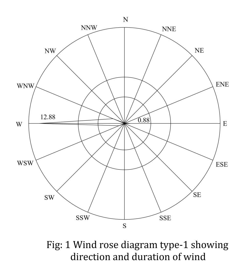
Type1:Showingdirectionanddurationofwind.
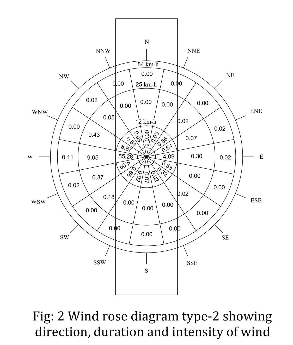
Type2:Showingdirection,durationandintensityofwind. Eachoftheabovetypeofplottingwillnowbediscussed. Type 1 wind rose, direction and duration of wind: The radial lines indicate the wind direction and each circle representsthedurationofwindtoacertainscale.Thetotal percentageofwindblowinginNorthis6.10andaccordingly, this point is marked along North direction. Similarly, all othervaluesareplottedandthen
Joinedbythestraightlines.Thebestdirectionofrunwayis indicatedalongthedirectionofthelongestlineonthewind rose diagram. WNW-ESE is the best orientation for the runway.Thistypeofwindrosedoesnotconsidertheeffect ofthecrosswindcomponent.
International Research Journal of Engineering and Technology (IRJET) e-ISSN: 2395-0056
Volume: 11 Issue: 07 | July 2024 www.irjet.net p-ISSN: 2395-0072
Type II wind rose, direction,duration and intensity of wind: Thatthepercentageoftimeduringwhichthewind velocityislessthan6km/h.worksoutto(100-88)=12.This periodiscalledthecalmperiodanditdoesnotinfluencethe operations of landing and take-off because of low wind velocity. Thus, the wind velocities below 6 km/h. have no effectonthefixingoforientationofarunway.
Theconstructionanduseofthistypeofwindrosediagram areillustratedfollowingprocedureisadopted:
(i) Theconcentriccircleswithradiicorrespondingto6, 25,50and80km/h.tosomescalearedrawn.Thus, each circle represents the wind velocity to some scale.
(ii) Startingwithcenteroftheconcentriccircles,the16 radialdirectionsareshownontheoutercircle.The mid-pointsof16arcsontheoutermostconcentric circlearemarkedandtheyaregiventhecardinal directionsofcompasslikeN,NNE,NE,ENE,E,etc.
(iii)Therecordeddurationofwindsandexpressedas percentageareshownforeachcardinaldirectionin the sector pertaining to that direction. It may be noted that the cardinal direction is central to its sector. Taking the wind data for N direction, the duration of 6-25, 25-50 and 50-80 km/h. wind velocitiesareshownin3pertinentpartsoftheN directionsectoras4.6,1.4and0.1%.Similarly,for NNEdirection,thedurationsinthesectorofNNE direction are shown as 3.4, 0.75 and 0.00%. The durationsofwindvelocitiesarethusshowninall thesectorstocompletethewindrosediagram.
(iv)Atransparentrectangulartemplateorpaperstripis taken.Itslengthshouldbeslightlygreaterthanthe diameter of the wind rose diagram and its width should be greater than twice the allowable cross windcomponenti.e.(2x25)=50km/h.Thescale forcross windcomponentshouldbethesameas that of the concentric circles of the wind rose diagram. Along the center of the length of this template, a line is marked corresponding to the directionofrunway.Thetwoparallellines,oneon eithersideofthecenter-line,isdrawnatadistance equaltotheallowablecrosswindcomponenti.e.25 km/h.fromthecenter-line.Inotherwords,thetwo parallellinesare50km/h.awayfromeachother.
(v) The wind rose diagram is fixed in position on a drawingboard.Aholeisdrilledinthecenterofthe templateanditisplacedonthewindrosediagram suchthatitscenterliesoverthecenterofthewind rosediagram.Inthisposition,thetemplateisfixed by a pin passing through its center so that the templatecanrotateaboutthispinasaxis.
(vi)The template is rotated and is placed along a particulardirection.Inthispositionofthetemplate, thedurationof6-25,25-50and50-80km/h.winds arereadforthecardinaldirectionslyingbetween the two extreme parallel lines marked on the template. The sum of all these durations is expressedasthepercentageanditgivesthetotal windcoverageforthatdirection
(vii) Thetemplateisthenrotatedandisplaced in the next direction. The total wind coverage is calculated and the process is repeated for all the directions.
(viii) The direction which gives the maximum wind coverage is the suitable direction for the orientationoftherunway.
Followingpointsshouldbenoted:
(i) If the extreme parallel lines on the template cut someofthethreesignificantpartsofasectorfora cardinal direction, the values of the truncated portionsofthesepartslyinginsidetheparallelline shouldbefoundbyeyeestimation.Thisisdoneon the assumption that the full part represents the percentageofdurationmarkedonit.
(ii) Themaximumwindcoverageofarunwayshouldbe 95%ontheassumptionthatthecalmsare5%.Ifa single runway is not sufficient to provide the necessary coverage, two or more number of runways should be planned to get the desired coverage.
(iii)Ifproperwinddataforanentirelynewlocationare not recorded, the study of nearby measuring stations may be made. If the surrounding area is fairly level, the records of these stations may indicate the winds at the site of the proposed airport. If the area is however hilly, the wind patternisoften dictated by thetopographyandit will prove dangerous to utilize the records of stationssituatedsomedistanceawayfromthesite. In such cases, it will be advisable to study the topographyoftheregionatleastforoneyearand correlate the observations from the information gatheredfromtheoldresidentsofthelocality.
International Research Journal of Engineering and Technology (IRJET) e-ISSN: 2395-0056
Volume: 11 Issue: 07 | July 2024 www.irjet.net p-ISSN: 2395-0072
International Research Journal of Engineering and Technology (IRJET) e-ISSN: 2395-0056
Volume: 11 Issue: 07 | July 2024 www.irjet.net p-ISSN: 2395-0072
Theidealorientationdecidedfromthestudyofthe wind rose diagram may have to be slightly altered or changedbecauseofthefollowingfactors:
1. Excessive grading: If the orientation of runway demands excessive grad and earthwork, it will have to be suitably modified even though it might have been satisfactory with respect to the safe approaches and the windcoverage.
2. Noise nuisance: Thelocationofrunwayshouldbesuch thatitdoesnotobstructioncreateexcessivenoisenuisance tothesurroundingdevelopedresidentialareasandpublic placesofimportance.Thisfactormayalsosometimescause thechangeindirectionoftherunwayasdecidedbythewind rosediagram.
3. Obstruction: Theabsenceofobstructioninthelayoutof therunwayismoreimportantthantheconsiderationofthe permissible cross wind component. Hence, the runway directionprovidingfewerobstructionintheapproachzone ispreferredtoonehavinggreaterwindcoverage.
2.2.1 Basic runway length:-
The length of runway based on the following assumedconditionisknownasthebasicrunwaylength:
i. Nowindisblowingontherunway.
ii. Theaircraftisloadedtoitsfullloadingcapacity
iii. Theairportissituatedatsea-level.
iv. There is no wind blowing on the way to the destination.
v. Therunwayislevelledinthelongitudinalorinother words.Ithaszeroeffectivegradient.
vi. Thestandardtemperatureismaintainedalongthe way
vii. The standard temperature of 15°C exists at the airport.
The manner in which an aircraft actually performs the landingandtake-offwilldecidetoalargeextentthelengthof arunway.
Followingthreecaseswillbeconsidered:
(1)Normallanding
(2)Normaltakeoff
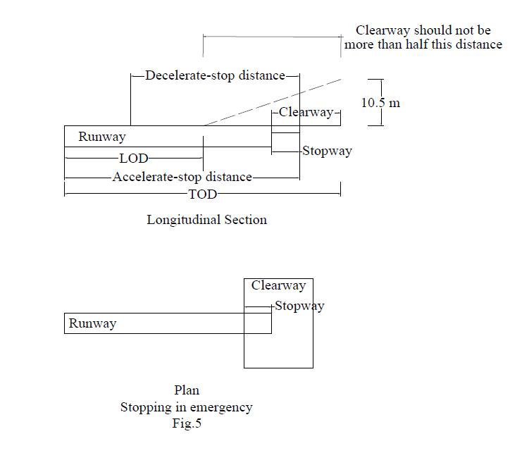
(3)Stoppinginemergency.
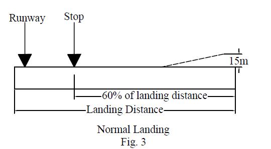
(1) Normal landing: The aircraft should come to a stop Within 60 per cent of the landing distance assumingthatthepilot makesanapproachatthe proper speed and crosses the threshold of the runway at a height of 15 m. The beginning of the runwayportiontobeusedforlandingisknownas
thethreshold.Therunwayoffullstrengthpavement isprovidedfortheentirelandingdistance.
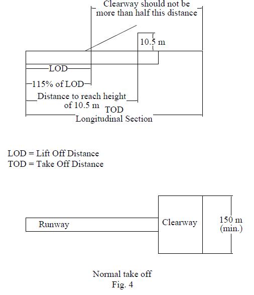
(2) Normal take off: Thetake-offdistance(TOD)mustbe, for a specific weight aircraft. 115 per cent of the actual distance the aircraft uses to reach a height of 10.5 m. The distancetoreachtheheightof10.5mshouldbeequalto115 percentofthelift-offdistance(LOD).
The normal take off requires a clearway which is definedasanareabeyondtherunwaynotlessthan150m wide,centrallylocatedabouttheextendedcenter-lineofthe runwayandunderthecontroloftheairportauthorities.Itis expressedintermsofaclearwayplaneextendingfromthe end of the runway with an upward hit me slope not exceeding1.25percent.Itistobeseenthattheclearwayis freefromanyobstruction.Theclearwayshouldnotbemore thanone-halfthedifferencethebetween115percentofthe LODandTOD.
International Research Journal of Engineering and Technology (IRJET) e-ISSN: 2395-0056
Volume: 11 Issue: 07 | July 2024 www.irjet.net p-ISSN: 2395-0072
(3) Stopping in emergency: Fortheenginefailurecase, theTODistheactualdistancerequiredtoreachaheightof 10.5 m with no percentage applied. It also incidentally recognizes the infrequency of occurrence of the engine failure.Incaseofanenginefailure,sufficientdistanceshould be available to stop the airplane rather than continue the take-off. This distance is known as the accelerate-stop distance.
Itisrequiredtoprovideaclearwayorastopwayor bothinthiscase.Thestopwayisdefinedasa rectangular areaattheendofrunwayandinthedirectionoftake-off.It isapavedareainwhichanaircraftcanbestoppedafteran interruptedtakeoffduetoenginefailure.Itswidthisatleast equaltothewidthofrunwayandthethicknessofpavement less than that of the runway, but yet sufficient to take the loadofaircraftwithoutfailure.Theclearwayshouldnotbe morethanone-halfthedifferencebetweenTODandLOD.
Alltheabovethreecasesareconsideredforthejetengine aircrafts.Forthepistonengineaircrafts,onlythefirstand thethirdcasesareconsidered.Thecasegivingthelongest runwaylengthisfinallyrecommended.
Basicrunwaylength-
Takeoffspeedofplane(V)=290km/h.
Decisionspeed(Vf)=290km/h.
Velocity=(290X1000)/3600=81m/s.
Theaccelerationisassumedas,(a)=1m/s.
Actualvelocityisdifferencebetweenfinalvelocityandfinal velocity.
Va =(Vf-Vi)/2=(81-0)/2=40.5m/s2
Hence,
(a) Totaldistance(Takeoffrun)=40.5X81=3280m.
Whenalltheenginesareoperating,
(b) 115%oftake-offrun=(115X2915)=3352m.
Takingthemaximumvalueofcase(a)and(b)
Takeoffrunfromaircraftperformanceis3352m.
To get actual length of the runway, the following three correctionaretobeappliedtothecalculatedbasicrunway length:-
1) Correctionforelevation.
2) Correctionofgradient.
3) Correctionfortemperature.
(1)Correction forelevation:-Aspertherecommendation ofICAO,thebasicrunwaylengthshouldbeincreasedatthe rate of 7 per cent 300 m rise in elevation of airport above meansealevel.Thiscorrectionisrequiredbecausetheair density reduces s the elevation increases which in turn reducetheliftonthewingsoftheaircraft.These,theaircraft willrequiremoregroundspeedtorisetotheairforachieving morespeed,thelongerlengthofrunwaywillberequired.
Thebasiclengthselectedforrunwayshouldbeincreasedat therateof7%per300melevation.
Runwayelevationattheaerodrome=12m.
ElevationofPurandarairportis739m.
Runwaytakeofflengthcorrectedforelevation
=((7/100)X(739/300)X3352)+3352)
=3929.99≈3939m
(2) Correction for temperature:-The rise in airport reference temperature has the same effect as that of the increases in its elevation above mean sea-level. After the basic length is corrected for the elevation of airport, it is further increased at threat of 1% rise in airport reference temperatureabovethestandardatmospherictemperatureat theelevation.Theairportreferencetemperatureisworked outbythefollowingexpression: Airportreferencetemperature=(T1+(T2-T1)/3)
Where,
T1=Monthlymeanoftheaveragedailytemperatureforthe hottestmonthoftheyear.
T2=Monthlymeanofthemaximumdailytemperatureforthe samemonth.
The standard temperature at the airport site can be determined by reducing the standard mean sea-level temperatureof15℃atrateof6.5℃perthousandmeterrise inelevation.
=[TakeofrunX(ART-Standardtemperature)X0.01)+Take offrun.
ART=Aerodromereferencetemperature.
ART=38.33℃
Standardtemperatureat739m.Elevationat15℃ =[3930X(38.33-15)X0.01]+3930
International Research Journal of Engineering and Technology (IRJET) e-ISSN: 2395-0056
Volume: 11 Issue: 07 | July 2024 www.irjet.net p-ISSN: 2395-0072
=4846.86≈4847m.
(3) Correction for gradient: - As the gradient becomes steep,moreconsumptionofenergytakesplaceandlonger lengthoftherunwaywillberequiredtoattainthedesired ground speed. The ICAO does not give any specific recommendation for the increase in length due to the effectivegradient.
The maximum difference in elevation between the highest andlowestpointsofrunwaydividedbythetotal lengthof runwayisknownastheeffectivegradient.AccordingtoFAA (Federal Aviation Administration) of U.S.A., the runway lengthafterbeingcorrectedforelevationandtemperature shouldfurtherbeincreasedattherateof20%forevery1℃ ofeffectivegradient.
Effectivegradient=0.5%.
Applyingcorrectionfortheeffectivegradientattherateof 20%foreach1℃effectivegradient.
=(20/100X4847)X(0.5/100)+4847
=4.84+4847
=4851.84≈4852m.
3. CONCLUSIONS
Themostimportantpointsofthisstudycanbesummarized asfollows:-
i. Fromthewinddatatheorientationoftherunwayis providedWesttoEastdirection ii. Fortheproposedairport,therunwaylengthis4852 meter.
REFERENCES
[1] https://earth.google.com/
[2] Khanna, S. K., and M. G., Arora Airport: Planning and Design.NemChand,1976.
[3] S.C.,andP.C.,Rangwala.,AirportEngineering Charotar, 1992.