
International Research Journal of Engineering and Technology (IRJET) e-ISSN: 2395-0056
Volume: 11 Issue: 07 | July 2024 www.irjet.net p-ISSN: 2395-0072

International Research Journal of Engineering and Technology (IRJET) e-ISSN: 2395-0056
Volume: 11 Issue: 07 | July 2024 www.irjet.net p-ISSN: 2395-0072
Akash Dewangan1 , Dr. R.R.L.Birali2 , Mr.Akhand Pratap Singh3
M.Tech Scholar1, Assistant Professor2, Assistant Professor3
Department of Civil Engineering
Shri Rawatpura Sarkar University Raipur Chhattisgarh ***
Abstract
Extensiveresearchisunderwaygloballyontheapplicationoffiber-reinforcedpolymer(FRP)wraps,laminates,andsheetsfor therepairandstrengtheningofreinforcedconcretestructures.Fiber-reinforcedpolymer(FRP)systemsofferahighlyeffective and economically viable alternative to traditional repair methods for enhancing the structural performance of weakened concretemembers.
This study focuses on the experimental investigation of the flexural and shear behavior of reinforced concrete (RC) beams strengthenedwithcontinuousglassfiberreinforcedpolymer(GFRP)sheets.Concretebeamsexternallyreinforcedwithepoxybonded GFRP sheets were tested to failure under a symmetrical two-point concentrated static loading system. Two experimental sets were utilized: SET I involved three beams deficient in flexure, including one control beam and two beams strengthenedwithGFRPsheetsinflexure;SETIIinvolvedthreebeamsdeficientinshear,includingonecontrolbeamandtwo beamsstrengthenedwithGFRPsheetsinshear.Thestrengtheningwasperformedwithvaryingamountsandconfigurationsof GFRPsheets.
Key experimental data, including load, deflection, and failure modes, were recorded for each beam. The study details the procedure for applying GFRP sheets and investigates the impact of the number of GFRP layers and their orientation on the ultimateload-carryingcapacityandfailuremodesofthebeams.
Keywords: ReinforcedConcreteBeams,GlassFiberReinforcedPolymer(GFRP),FlexuralStrengthening,ShearStrengthening, ExperimentalInvestigation,LoadCarryingCapacity,FailureModes.
Themaintenance,rehabilitation,andupgradingofstructuralmembersarecriticalchallengesincivilengineering.Manyolder structures,builttooutdateddesigncodes,arenowdeemedunsafeaccordingtocurrentstandards.Replacingtheseelementsis expensive and time-consuming, making strengthening a preferable method to enhance load-carrying capacity and extend servicelife.Infrastructuredecay,oftenduetodeteriorationordamage,haspromptedthedevelopmentofvariousrepairand strengtheningtechniques.
Structuralstrengtheningisneededfor:
IncreasedLoadRequirements:Changesinuseoradditionalloadsdemandenhancedcapacity.
UnanticipatedLoads:Structuresmustresistnewloadsfromwind,seismicforces,orblasts.
DeficienciesinDesign:Issueslikecorrosion,damage,ordesignerrorsnecessitatestrengthening.
Each project presents unique challenges, including space, constructability, and budget constraints. Strengthening typically involves addressing flexural, shear, axial, and torsional forces, and can be achieved through techniques such as section enlargement,externallybondedreinforcement,post-tensioning,andsupplementalsupports.
International Research Journal of Engineering and Technology (IRJET) e-ISSN: 2395-0056
Volume: 11 Issue: 07 | July 2024 www.irjet.net p-ISSN: 2395-0072
Strengtheningsystemscanbe:
Passive:Activatedonlywhenadditionalloadsareapplied,suchasbondingsteelplatesorFRPcomposites.
Active:Engagethestructureimmediatelybyintroducingexternalforces,likeexternalpost-tensioning.
Choosingthebestmethodrequiresconsidering:
StrengthIncrease:Desiredimprovementinloadcapacity.
MemberStiffnessChanges:Impactonstructuralperformance.
ProjectSizeandCost:Cost-effectivenessofmethodsforvariousprojectscales.
EnvironmentalConditions:Suitabilityofmethodsindifferentenvironments.
ConcreteStrengthandIntegrity:Effectivenessofbondingmethods.
DimensionalConstraints:Limitationsonspaceforsectionenlargement.
AccessibilityandOperationalConstraints:Impactonconstructiontimeandaccess.
MaterialandContractorAvailability:Accesstonecessaryresources.
LifecycleCosts:Totalcost,includingmaintenanceandconstruction.
Replacing steel reinforcement with fiber-reinforced polymers (FRPs) addresses corrosion issues, which compromise both steel and concrete integrity. FRPs prevent the deterioration associated with traditional steel reinforcement, which leads to reducedcross-sectionalstrengthandconcretedamageduetocorrosion.
Various techniques, including the external bonding of steel plates using epoxy adhesives, have been employed to strengthen concretestructures.Althougheffective,thismethodhasdrawbackssuchashighweight,difficultyinhandling,vulnerability to corrosion,andlimitedplatelengthsrequiringjoints.
Theutilizationofpre-stressedcompositeplates,atthetimeofbonding,forstrengtheningconcretemembershasbeenstudied only relatively recently in comparison with investigations of non-prestressed plates, although the benefits of external prestressingwithplatematerialshavebeenrecognizedformanyyears.Forexample,Peterson(1965)consideredtheexternal prestressing of timber beams using prestressed steel sheets and found significant improvements in bending stiffness and ultimate capacity. External prestressing with composite plates also provides these benefits as well as cost savings. Triantafillou and Deskovic (1991) noted that this method of prestressing is a more economical alternative to conventional prestressingmethodsusedinnewconstruction.Initialresearchonthestrengtheningofreinforcedconcretebeamsbyexternal plate prestressing at EMPA in Switzerland has been widely reported (Meier and Kaiser, 1991; Meier et al., 1993; Deuring, 1994). This work included the cyclic loading of a beam whose plate was prestressed to 50% of its strength. Although this prestressensuresthemeanstresslevelinthecyclicloadingwashigh,therewasnoevidenceofdamagetotheplateafter30 × 107 cyclesandthecrackingoftheconcretewaswellcontrolled.
The non-prestressed beam loading tests reported by Deuring (1993) revealed failures by the initiation of plate separation fromthebaseofashearcrack.Itwasfoundthatthecompressiontransferintotheconcretebytheplateprestresscoulddelay or even prevent this type of failure, thereby allowing the plate to reach its ultimate tensile strain so that the beam failed in flexure rather than by premature plate separation (Deuring, 1993). The ability of the plate to alter the failure mode from prematureplateseparationtoflexureisinfluencedbythepre-stressingforceandthecross-sectionalareaoftheplate.Oneof the conclusions of the work was that the greatest flexural resistance of a strengthened section is reached when the plate fracturesintension,eitherafteroratthesametimeasyieldoftheinternalsteelrebars.
International Research Journal of Engineering and Technology (IRJET) e-ISSN: 2395-0056
Volume: 11 Issue: 07 | July 2024 www.irjet.net p-ISSN: 2395-0072
Triantafillou et al. (1992) tested reinforced concrete beams in three point bending with various quantities of internal reinforcementandmagnitudesofCFRPplateprestress.Improvedcontrolofconcretecrackingwasbroughtaboutnotonlyby agreaterinternalreinforcementprovision,butalsobyhigherplateprestress,indicatingtheserviceabilityadvantagegainedby prestressing the composite. It was noted that prestressed composite plates can potentially act as the sole tensile reinforcement in new concrete construction and prefabrication is also possible due to the simplicity with which composites maybehandledandapplied.Theconfinementimposedbytheinitialcompressivestressatthebaseofthebeamwasthought tobecapableofimprovingtheshearresistanceofthemember.Also,anadvantagefromacostpointofviewisthatthesame strengthening to failure may be achieved with a prestressed plate of relatively small cross section, like that achieved with a largernon-prestressedplate(Triantafillouetal.,1992).
2.1 Objectives of the Study
Tostudytheflexuralbehaviorofreinforcedconcretebeams.
To examine the effect of GFRP strengthening on the ultimate load-carrying capacity and failure pattern of reinforced concretebeams.
Toanalyzetheshearbehaviorofreinforcedconcretebeams.
ToevaluatetheimpactofGFRPstrengtheningontheshearbehaviorofreinforcedconcretebeams.
3. Materials and Method
3.1 Materials
3.1.1 Concrete
ConcreteisaconstructionmaterialmadefromPortlandcement,water,andaggregatessuchassand,gravel,orcrushedstone. Thecementandwaterformapastethathardensthroughachemicalreaction,bindingtheaggregatesintoa strong,stone-like mass. The amount of cement paste is minimized to coat aggregate surfaces and fill voids, ensuring economy and strength. Proper water content is crucial; too much water weakens the concrete, while too little prevents proper curing. Concrete mixturesaredesignedforspecificcompressivestrengths,typically15to35MPa.Mixtureproportionsvary:arichmixturefor columnsmightbe1partcement,1partsand,and3partsstone,whilealeanmixtureforfoundationscouldbe1:3:6.Concrete canbedenseorporous,withadditivestoenhancepropertieslikewaterproofingorlightweight.Fullhardeningtakesatleast7 days,withstrengthincreasingastricalciumaluminatesandsilicateshydrate.
3.1.2 Cement
Cement is a material, generally in powder form, that can be made into a paste usually by the addition of water and, when molded or poured, will set into a solid mass. Numerous organic compounds used for adhering, or fastening materials, are called cements, but these are classified as adhesives, and the term cement alone means a construction material. The most widelyusedoftheconstructioncementsisportlandcement.Itisabluish-graypowderobtainedbyfinelygrindingtheclinker madebystronglyheatinganintimatemixtureofcalcareous andargillaceousminerals.Thechiefrawmaterialisamixtureof high-calciumlimestone,knownascementrock,andclayorshale.Blast-furnaceslagmayalsobeusedinsomecementsandthe cementiscalledportlandslagcement(PSC).Thecolorofthecementisduechieflytoironoxide.Intheabsenceofimpurities, thecolorwouldbewhite,butneitherthecolornorthespecificgravityisatestofquality.Thespecificgravityisatleast3.10. Portlandslagcement(PSC)–43grade(KornakCement)wasusedfortheinvestigation
3.1.3
Fine aggregate, or sand, is composed of mineral grains derived from rock disintegration. It is distinguished from gravel by grainsizeandfromclaysbytheabsenceoforganicmaterials.Sandsaretypically uniformingrainsizewhensortedbywater or wind, with commercial sand often sourced from riverbeds or sand dunes. Most sands are quartz and other siliceous materials,withcommerciallyvaluablesilicasandsbeingover98%pure.Beachsands,formedbywaveandtideabrasion,have smooth particles and are usually free of organic matter. These white sands, primarily silica, may also contain minerals like zircon,monazite,andgarnet,usedforextractingelements
© 2024, IRJET | Impact Factor value: 8.226 | ISO 9001:2008 Certified Journal | Page1084
International Research Journal of Engineering and Technology (IRJET) e-ISSN: 2395-0056
Volume: 11 Issue: 07 | July 2024 www.irjet.net p-ISSN: 2395-0072
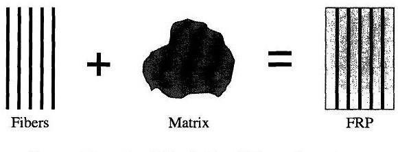
Continuousfiber-reinforcedmaterialswithapolymericmatrix(FRP)arecomposite,heterogeneous,andanisotropicmaterials that exhibit a linear elastic behavior up to failure. They are extensively used for strengthening civil structures due to their numerousadvantages,includinglightweight,excellentmechanicalproperties,andcorrosionresistance.FRPscomeinvarious forms, such as laminates for regular surfaces and bi-directional fabrics that adapt to the member's shape. These composites areidealforpreservingtheaestheticsofhistoricalbuildingsorforsituationswheretraditionalstrengtheningtechniquesare ineffective.
International Research Journal of Engineering and Technology (IRJET) e-ISSN: 2395-0056
Volume: 11 Issue: 07 | July 2024 www.irjet.net p-ISSN: 2395-0072
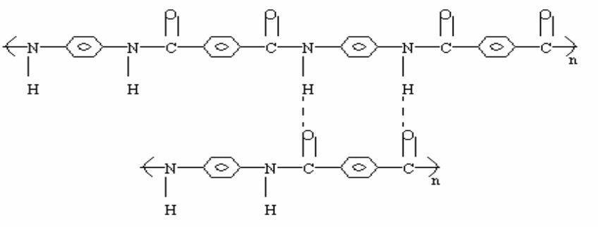
Fig. 3.3 Structure of Aramid fiber
Table 3.3 Properties of Epoxy Resin
Property
Density,Density(g/cm3) 1.2-1.3
TensileModulus,Mpa 55-130
TensileModulus,Gpa 2.75-4.10
ThermalExpansion,10-6/C 45-65
WaterAbsorption%in24h 0.08-0.15
Thesuccessofthestrengtheningtechniquecriticallydependsontheperformanceofthe epoxyresinused.Numeroustypesof epoxy resins with a wide range of mechanical properties are commercially available. These epoxy resins are generally two partsystems,aresinandahardener.TheresinandhardenerareusedinthisstudyisAralditeLY556and Hardener HY 951, respectively. Araldite LY-556, an unmodified epoxy resin based onBisphenol-A and the hardener (Ciba-Geig, India) HY 951 (8% of total Epoxy taken) analiphaticprimaryamine,weremixedproperly.
Table 3.4 Properties of Epoxy Resin and Hardener
Properties
Araldite LY 556
Hardener HY 951
Color Clear Colorless
Odor Slight Ammonia
PhysicalState Liquid Liquid
Solubilityinwater Insoluble Miscible
International Research Journal of Engineering and Technology (IRJET) e-ISSN: 2395-0056
Volume: 11 Issue: 07 | July 2024 www.irjet.net p-ISSN: 2395-0072
Theexperimentalstudyconsistsofcastingoftwosetsofreinforcedconcrete(RC)beams.InSETIthreebeamsweakinflexure were casted, out of which one is controlled beam and other two beams were strengthened using continuous glass fiber reinforced polymer (GFRP) sheets in flexure. In SET II three beams weak in shear were casted, out of which one is the controlledbeamandothertwobeamswerestrengthenedbyusingcontinuousglassfiberreinforcedpolymer(GFRP)sheetsin shear. The strengthening of the beams is done with varying configuration and layers of GFRP sheets. Experimental data on load,deflectionandfailuremodesofeachofthebeamswereobtained.Thechangeinloadcarryingcapacityand failuremode ofthebeamsareinvestigatedastheamountandconfigurationofGFRPsheets arealtered.Thefollowingchapterdescribesin detailtheexperimentalstudy.
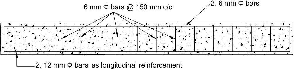
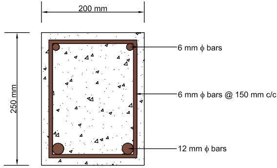
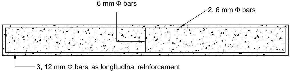
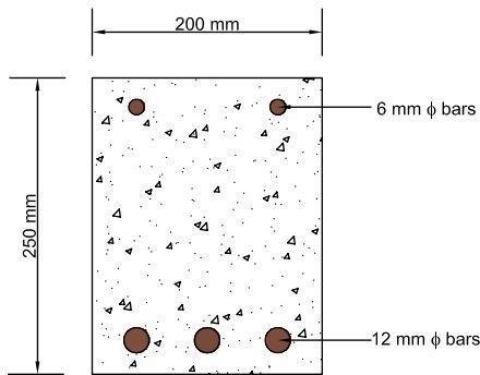
Twosetsofbeamswerecastedforthisexperimentaltestprogram.InSETIthreebeams(F1,F2andF3)weakinflexurewere casted using same grade of concrete and reinforcement detailing. In SET II three beams (S1, S2 and S3) weak in shear were casted using same grade of concrete and reinforcement detailing. The dimensions of all the specimens are identical. The cross sectional dimensions ofthe boththeset of beams is250 mm by200 mmand length is2300 mm.InSET Ibeams 2,12 reinforcement and without any stirrups.
International Research Journal of Engineering and Technology (IRJET) e-ISSN: 2395-0056
Volume: 11 Issue: 07 | July 2024 www.irjet.net p-ISSN: 2395-0072
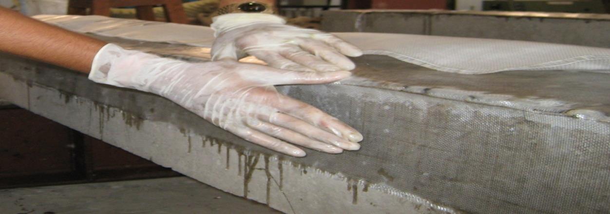
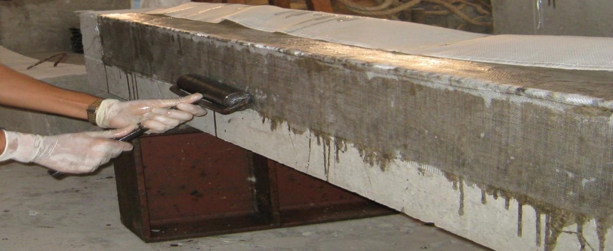
Before bonding composite fabric to the concrete, the surface was roughened with coarse sandpaper and cleaned with an air blower to remove dirt and debris. The epoxy resin was mixed as per the manufacturer's instructions (100 parts by weight AralditeLY556and8partsbyweightHardenerHY951)untilitachievedauniformcolor.Aftercuttingthefabrictosize,the epoxyresinwasappliedtotheconcretesurface.Thecompositefabricwasthenplacedontheepoxy,andtheresinwasworked through the fabric using a roller to remove air bubbles. A second layer of epoxy resin was applied, and a GFRP sheet was placed on top, with the process repeated. Uniform pressure was applied during epoxy curing to ensure good contact and removeexcessresin.Concretebeamswithglassfiberfabricwerecuredatroomtemperaturefor24hoursbeforetesting.

International Research Journal of Engineering and Technology (IRJET) e-ISSN: 2395-0056
Volume: 11 Issue: 07 | July 2024 www.irjet.net p-ISSN: 2395-0072
3.5
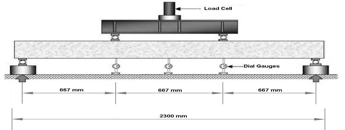
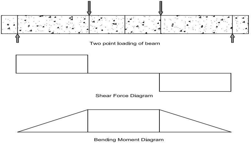
All specimens were tested inthe“Structural Engineering”Laboratory atNational Institute of Technology, Raipur.After a 28daycuringperiod,thebeamswerewashedandcleanedforcrackvisibility.Testinginvolvedatwo-pointloadingarrangement to assess the bending capacity of the central portion while minimizing shear effects.The setup included a load cell and sphericalseatingonaspreaderbeamsupportedbyrollersonsteelplates.Thetestmemberwassupportedonrollerbearings with similar spreader plates. The loading frame was designed to handle expected loads without significant distortion, with considerationsforcrackobservation,deflectionreadings,andsafety.
Eachspecimenwaspositionedontwosteelrollers,150mmfromeachend,witha 2000mmspandividedintothree667mm sections.Loadingwasappliedusinga 100kN hydraulicjack.Threedial gaugesrecordeddeflections:oneatthecenterofthe beamandtwobeneaththepointloads. © 2024, IRJET | Impact Factor value: 8.226 | ISO 9001:2008 Certified Journal | Page1089
International Research Journal of Engineering and Technology (IRJET) e-ISSN: 2395-0056
Volume: 11 Issue: 07 | July 2024 www.irjet.net p-ISSN: 2395-0072
5. Results and Discussions
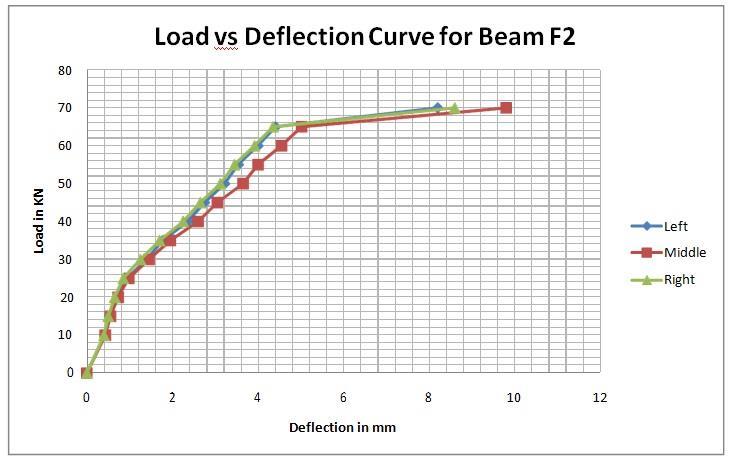
Twosetsofbeamsweretestedfortheirultimatestrengths.InSETIthreebeams(F1,F2andF3)weakinflexurearetested.In SET II three beams (S1, S2 and S3) weak in shear are tested. The beams F1and S1 were taken as the control beams. It was observed that the beams F1 and S1 had less load carrying capacity when compared to that of the externally strengthened beams using GFRP sheets. In SET I beams F2 is strengthened only at the soffit of the beam and F3 is strengthened up to the neutralaxisofthebeamalongwiththesoffitofthebeam.SETIIbeamsS2isstrengthenedonlyatthesidesofthebeaminthe shearzoneandS3isstrengthenedbyU-wrappingofthe GFRPsheetsintheshearzoneofthebeam. Deflection behaviorand theultimateloadcarryingcapacityofthebeamswerenoted. The ultimateloadcarryingcapacityofall thebeamsalongwith thenatureoffailureisgiveninTable5.1.
Volume: 11 Issue: 07 | July 2024 www.irjet.net
Table 5.1 Ultimate load and nature of failure for SET I and SET II beams
Theloaddeflectionhistoryofallthebeamswas recorded.Themid-span deflectionofeachbeamwascomparedwiththatof theirrespectivecontrolbeams.Alsotheload deflectionbehaviourwascomparedbetweentwowrappingschemeshavingthe samereinforcement.ItwasnotedthatthebehaviouroftheflexureandsheardeficientbeamswhenbondedwithGFRPsheets werebetterthantheircorrespondingcontrolbeams.Themid-spandeflectionsweremuchlowerwhenbondedexternallywith GFRP sheets. The graphs comparing the mid-span deflection of flexure and shear deficient beams and their correspondingcontrolbeamsareshowninFigs5.4and5.8.TheuseofGFRPsheethad effectindelayingthegrowth ofcrack formation.InSET Iwhen boththe wrappingschemes wereconsideredit wasfound thatthe beamF3 withGFRPsheetupto theneutralaxisalong withthesoffithadabetterloaddeflectionbehaviourwhencomparedtothebeamF2with GFRPsheet onlyatthesoffitofthebeam.InSETIIwhenboththewrappingschemeswere considereditwasfoundthatthebeamS3with UwrappingofGFRPsheethada betterload deflection behaviour when compared to the beam S2 with GFRP sheet only at the sides ofthebeam.
International Research Journal of Engineering and Technology (IRJET) e-ISSN: 2395-0056
Volume: 11 Issue: 07 | July 2024 www.irjet.net p-ISSN: 2395-0072
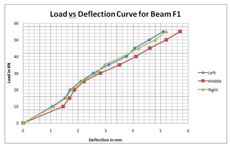
BeamF1wasthecontrolbeamofSETIbeamswhichwereweakinflexurebut stronginshear.InbeamF1strengtheningwas notdone.Twopointstaticloadingwasdoneon the beam and at the each increment of the load, deflection at the left, right and middledialgaugesweretaken.Usingthisloadanddeflectionofdata,loadvsdeflectioncurveis plotted.Attheloadof30 KNinitialcracksstartedcomingonthebeams.Furtherwithincreaseinloadingpropagationofthecrackstookplace.Thebeam F1failedcompletelyinflexure.
5.7 Comparison of Results
Theresultsofthetwosetofbeamstestedareshownin Table5.1.Thefailure mode, loadatinitialcrackandultimateloadof thecontrolbeamswithoutstrengtheningandthebeamsstrengthenwithtwolayersGFRPsheetarepresented.Thedifficulties
International Research Journal of Engineering and Technology (IRJET) e-ISSN: 2395-0056
Volume: 11 Issue: 07 | July 2024 www.irjet.net p-ISSN: 2395-0072
inherent to the understanding of strengthen structural member behavior subjected to flexure and shear has not allowed developing a rigorous theoretical design approach. The complexity of the problem has then made necessary an extensive experimental research. Moment of resistance of the SET I beams was calculated analytically and was compared with the obtainedexperimentalresults.
Table 5.2 Comparison of ����Value Obtained From Analytical and Experimental Study
6. Conclusion
The experimental investigation into the flexural and shear behavior of reinforced concrete (RC) beams strengthened with GlassFiberReinforcedPolymer(GFRP)sheetshasyieldedseveralkeyfindings:
1. Flexural Strengthening (SET I)
Beam Strengthening Results: Strengthening beams at the soffit and extending up to the neutral axis significantly enhancestheultimateload-carryingcapacity.BeamF2,strengthenedonlyatthesoffit,showeda33%increase,whileBeam F3,strengthenedatboththesoffitandthesidesuptotheneutralaxis,demonstrateda43%increaseoverthecontrolbeam F1.Theadditionalstrengtheningattheneutralaxisledtoa7%improvementoverF2.
Failure Modes: Control beams failed in flexure, while strengthened beams exhibited flexure-shear failure, which is more critical as it provides less warning before failure. Therefore, shear strengthening should be considered alongside flexural strengthening.
Cost and Effectiveness: Strengthening up to the neutral axis, while improving load capacity, incurs significantly higher costs(approximatelythreetimesmore)thanstrengtheningonlyatthesoffit.Theincreaseinload-carryingcapacityisnot proportionatetothecost,suggestingthattargetedstrengtheningmaybemorecost-effective.
2. Shear Strengthening (SET II)
Beam Strengthening Results: The control beam S1, intentionally made weak in shear, failed as expected. Strengthened beamsS2andS3showedimprovementsinload-carryingcapacityandcrackbehavior.BeamS2,withGFRPsheetsapplied onlytothevertical sides,showeda 31%increasein ultimateloadcapacitycomparedtoS1.Beam S3,strengthened byUwrappingintheshearzone,anddemonstrateda48%increaseoverS1anda13%improvementoverS2.
Failure Modes: Strengthenedbeamsprimarilyexperiencedflexuralfailureratherthanshearfailure,indicatingthatGFRP sheets effectively increase shear strength while delaying the onset of flexural failure. The bonding between GFRP sheets andconcreteremainedintactuntilfailure,emphasizingtheeffectivecompositeaction.
Shear Strength Restoration: The use of GFRP sheets effectively restores or upgrades the shear strength of beams, resultinginincreasedshearstrengthandstiffnesswithminimalvisibleshearcracks.
ThisresearchprovidesacomprehensiveanalysisoftheimpactofGFRPsheetstrengtheningontheflexuralandshearbehavior ofRCbeams.Futureresearchcouldfocuson:
a) Long-Term Performance: Assessing the long-term durability and performance of GFRP-strengthened beams under variousenvironmentalconditionsandloadscenarios.
© 2024, IRJET | Impact Factor value: 8.226 | ISO 9001:2008
International Research Journal of Engineering and Technology (IRJET) e-ISSN: 2395-0056
Volume: 11 Issue: 07 | July 2024 www.irjet.net p-ISSN: 2395-0072
b) Different GFRP Configurations: Investigatingother configurationsandapplication methodsofGFRPsheetsto optimize strengtheningtechniquesfordifferenttypesofstructuraldeficiencies.
c) Cost-Benefit Analysis: Performing a detailed cost-benefit analysis to evaluate the economic feasibility of various GFRP strengtheningmethodscomparedtotraditionalreinforcementtechniques.
d) Field Studies: Conductingfieldstudiesonexistingstructurestovalidatelaboratoryfindingsandunderstandthepractical challengesofimplementingGFRPstrengtheninginreal-worldconditions.
e) Hybrid Systems: Exploring the combination of GFRP with other strengthening materials and techniques to enhance overallstructuralperformanceandcostefficiency.
ThisworklaysthefoundationforfurtherexplorationintotheapplicationofGFRPinstructuralengineering,offeringvaluable insightsintoitseffectivenessinimprovingthestrengthandsafetyofreinforcedconcretestructures.
References
1. M. A. Shahawy, M. Arockiasamy, T. Beitelman, R. Sowrirajan “Reinforced concreterectangular beams strengthened withCFRPlaminates”Composites:PartB27B(1996)225-233
2. Victor N. Kaliakin, Michael J. Chajes and Ted F. Januszka “Analysis of concrete beams reinforced with externally bondedwoven composite fabrics”Composites:Part B27B(1996)235-244
3. KojiTakeda,YoshiyukiMitsui, Kiyoshi Murakami, Hiromichi Sakai andMoriyasuNakamura“Flexuralbehaviourof reinforced concrete beamsstrengthened withcarbon fibre sheets”Composites Part A 27A(1996)981-987
4. G.Spadea,F.BencardinoandR.N.Swamy“StructuralBehaviorofCompositeRCBeamswithExternallyBondedCFRP” JournalofCompositesforConstructionVol.2, No.3.August,1998.132-137
5. Ahmed Khalifa, William J. Gold, Antonio Nanni, and Abdel Aziz M.I. “Contributionof externally bonded FRP to shear capacityofRCflexuralmembers”JournalofCompositesforConstruction,Vol. 2. No.4,November,1998.195-202
6. N. F. Grace, G. A. Sayed, A. K. Soliman and K. R. Saleh “Strengthening Reinforced Concrete Beams Using Fiber ReinforcedPolymer(FRP)Laminates”ACIStructuralJournal/September-October1999.865-875
7. B. Taljsten and L. Elfgren “Strengthening concrete beams for shear using CFRP- materials: evaluation of different applicationmethods”Composites:PartB31(2000)87–96
8. Ahmed Khalifa, Antonio Nanni “Improving shear capacity of existing RC T-section beams using CFRP composites” Cement&ConcreteComposites22(2000)165-174
9. ThanasisC.TriantafillouandCostasP.Antonopoulos“Designofconcreteflexuralmembersstrengthenedinshearwith FRP”JournalofCompositesforConstruction,Vol.4,No.4,November,2000.198-205
10. V.P.V. Ramana, T. Kant, S.E. Morton, P.K. Dutta, A. Mukherjee and Y.M. Desai “Behavior of CFRPC strengthened reinforced concrete beams with varying degreesofstrengthening”Composites:PartB31(2000)461-470
11. D. Kachlakev and D.D. McCurry “Behavior of full-scale reinforced concrete beams retrofitted for shear and flexural withFRPlaminates”Composites:PartB31(2000)445-452
12. AlexLi,CheikhnaDiagana,YvesDelmas“CRFPcontributiontoshearcapacityof strengthenedRCbeams”Engineering Structures23(2001)1212–1220
13. J. F. Bonacci and M. Maalej “Behavioral trends of RC beams strengthened with externally bonded FRP” Journal of CompositesforConstruction,Vol.5,No.2,May,2001,102-113
International Research Journal of Engineering and Technology (IRJET) e-ISSN: 2395-0056
Volume: 11 Issue: 07 | July 2024 www.irjet.net p-ISSN: 2395-0072
14. Ahmed Khalifa, Antonio Nanni “Rehabilitation of rectangular simply supported RC beams with shear deficiencies usingCFRPcomposites”ConstructionandBuildingMaterials16(2002)135–146
15. Bjorn Taljsten “Strengthening concrete beams for shear with CFRP sheets” Construction and Building Materials 17 (2003)15–26
16. C. Diagana, A.Li, B. Gedalia, Y. Delmas “Shear strengthening effectiveness with CFF strips” Engineering Structures 25 (2003)507–516
17. M.N.S.Hadi“Retrofittingofshearfailedreinforcedconcretebeams”CompositeStructures62(2003)1–6
18. Sergio F. Brena, Regan M. Bramblett, Sharon L. Wood, and Michael E. Kreger “Increasing Flexural Capacity of Reinforced Concrete Beams Using Carbon Fiber- Reinforced Polymer Composites” ACI Structural Journal/JanuaryFebruary2003.36-46
19. Bimal Babu Adhikary, Hiroshi Mutsuyoshi, and Muhammad Ashraf “Shear Strengthening of Reinforced Concrete Beams Using Fiber-Reinforced Polymer Sheets with Bonded Anchorage” ACI Structural Journal/September-October 2004.660-668
20.ZhichaoZhangandCheng-TzuThomasHsu“ShearStrengtheningofReinforced ConcreteBeams UsingCarbon-FiberReinforcedPolymerLaminates”JournalofCompositesforConstruction,Vol.9,No.2,April1,2005.158-169.