
International Research Journal of Engineering and Technology (IRJET) e-ISSN: 2395-0056
Volume: 11 Issue: 07 | July 2024 www.irjet.net p-ISSN: 2395-0072

International Research Journal of Engineering and Technology (IRJET) e-ISSN: 2395-0056
Volume: 11 Issue: 07 | July 2024 www.irjet.net p-ISSN: 2395-0072
Ajay
B. Tech Student, Dept. of Mechanical Engineering, SAE NIT Kurukshetra National Institute of Technology Kurukshetra, Haryana, India
Abstract - This paper presents the design and analysis of a two-stage reduction gearbox for a Formula Electric Vehicle (FEV). The gearbox is designed to meet the specific performancerequirementsoftheFEV,focusingonefficiency, weight reduction, and compactness. The design process includesselectingappropriategearratiostooptimizetorque and speed based on the vehicle's electric motor characteristics. A detailed analysis using Finite Element Analysis (FEA) is conducted to evaluate the structural integrity and durability of the gearbox components under operational loads. Additionally, material selection is performed to ensure lightweight construction without compromisingstrength.The gearbox'sthermalperformance is also assessed to ensure reliable operation under varying conditions. The final design demonstrates a significant improvement in power transmission efficiency and vehicle performance. Results indicate that the two-stage reduction gearbox effectively balances the trade-offs between torque amplification and speed reduction, contributing to the overallenhancementoftheFEV'sdynamicperformance.This studyprovidesacomprehensiveapproachto gearboxdesign in electric vehicles, offering insights into achieving high efficiencyandrobustnessinhigh-performanceapplications.
Key Words: FEV, Gears, Gear ratios, shaft, Bearing, Power transmission efficiency
TherapidevolutionofFormulaElectricVehicles(FEVs)has necessitated advancements in powertrain components to enhance performance, efficiency, and reliability. A critical component in this evolution is the gearbox, which must efficiently translate the high-speed, low-torque output of electricmotorsintotheoptimaltorqueandspeedrequired by the vehicle's wheels. This paper focuses on the design andanalysisofa two-stagereductiongearboxtailoredfor FEVs. The primary objective is to develop a gearbox that maximizespowertransmissionefficiencywhileminimizing weight and spatial footprint, essential for the competitive edgeinFEVracing.
Thedesignprocessbeginswithselectingappropriategear ratios to achieve the desired balance between torque amplificationandspeedreduction,consideringthespecific characteristics of the electric motor used in the FEV. Advanced computational tools, including Finite Element Analysis (FEA), are employed to assess the structural integrity and durability of the gearbox under dynamic loads. Material selection is critical, aiming for lightweight yet robust components to withstand the demanding
operational conditions. This study also addresses thermal management to ensure consistent performance. The resultinggearboxdesignaimstosignificantlyenhance the FEV’s dynamic performance, providing a comprehensive approach to efficient and robust gearbox design in highperformanceelectricvehicles.
1.1
Material selection focuses on lightweight yet strong materials, such as high-strength aluminum alloys and advanced composites, to reduce the gearbox's overall weight without compromising durability. These materials provide excellent mechanical properties, including high strength-to-weight ratios and good thermal conductivity, ensuring the gearbox can withstand the demanding operationalconditionsofFormulaElectricVehicles(FEVs).
TABLE:MATERIALPROPERTY
PROPERTIES
Materialselected
In this paper, we choose EN24 material for the gearbox components due to its optimal balance of strength, toughness, and wear resistance, crucial for the demanding conditionsofFormulaElectricVehicles(FEVs).EN24offers high tensile strength and excellent fatigue resistance, ensuringthegearboxcanwithstandsubstantialoperational stresseswhilemaintainingreliabilityandperformance.This material selection enhances the gearbox's capability, significantly improving the overall efficiency and competitiveedgeoftheFEV.
inputparametersforthedesignandanalysisofthetwostage reduction gearbox for a Formula Electric Vehicle (FEV):
International Research Journal of Engineering and Technology (IRJET) e-ISSN:
Volume: 11 Issue: 07 | July 2024 www.irjet.net
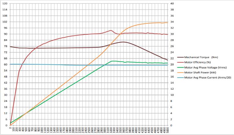
TABLEI:MOTORDATA
Motor
Peak
Graph:MotorData
TABLEII:FOR1st REDUCTION Parameter
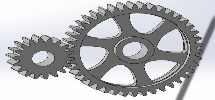
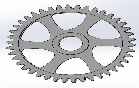
Figure:Gear1&Gear2
TABLEIII:FOR2ND REDUCTION
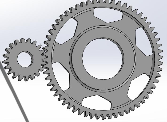
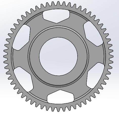
Gear3&Gear4
International Research Journal of Engineering and Technology (IRJET) e-ISSN: 2395-0056
Volume: 11 Issue: 07 | July 2024 www.irjet.net p-ISSN: 2395-0072
2.1 Design Calculation for Gear 1 and Gear 2
ModuleofGears=m
Pitchlinevelocity(v)
v=πDN/60
v=(3.14.18m.3000)/60
v=2.826m mm/s velocityfactor(Cv)
Cv=6/(6+v)
Cv=6/(6+2.826m)
Tangentialforceduetoratedtorque(Pt)
Pt=2T/D
Pt=13333/m
Cs=1
Effectiveloadontooth(Peff)
Peff=(Cs.Pt)/Cv
Peff=13333(6+2.826m)/6m
BEAMSTRENGTH
FactorofSafety=2
Endurancelimitstress(σ)=Sut/Factorofsafety
LewisFactor(Y)=0.302
Sb=m*b*σ*Y
Sb=1661��2
Now,
BeamStrength=Effectiveload*FactorofSafety 1661��2=(13333(6+2.826m)/6m).2
m = 3.5
WEARSTRENGTH
RatioFactorforinternalgear(Q)=2.T1/(T1+T2)
Q=0.620
Loadstressfactor(K)=(0.16(BHN)^2)/10000
K=6.76
Sw=D*b*Q*K
Sw=18(m)*8(m)*0.620*6.76
Sw=18(3.5)*8(3.5)*0.620*6.76
Sw=7393N
Similarly,
BeamStrength
Sb=1661��2
Sb=20347.25N
Effectiveload,
Peff=13333(6+2.826m)/6m
Peff=10090N
Since,
Sw>Peff,Sb>Peff
Designissafe
FactorofSafety,
Sb=Peff.Fos
Fos=20347.25/10090
Factorofsafety=2.01
(Note:Wecanadjustfactorofsafetybyincreasingwidthof Gear)
1st stagereduction=42/18=2.33
2.2 Design Calculation for Gear 3 and Gear 4
ModuleofGears=m
Pitchlinevelocity(v)
v=πDN/60
v=(3.14.20m.1287)/60
v=1.347m mm/s
velocityfactor(Cv)
Cv=6/(6+v)
Cv=6/(6+1.347m)
Tangentialforceduetoratedtorque(Pt)
Pt=2T/D
Pt=26667/m
Effectiveloadontooth(Peff)
Peff=(Cs.Pt)/Cv
Peff=26667(6+1.347m)/6m
BEAMSTRENGTH
FactorofSafety=2
International Research Journal of Engineering and Technology (IRJET) e-ISSN: 2395-0056
Volume: 11 Issue: 07 | July 2024 www.irjet.net p-ISSN: 2395-0072
Endurancelimitstress(σ)=Sut/Factorofsafety
LewisFactor(Y)=0.330
Sb=m.b.σ.Y
Sb=1815��2
Now,
BeamStrength=Effectiveload*FactorofSafety
1815��2=(26667(6+1.347m)/6m).2
m = 3.5
WEARSTRENGTH
RatioFactorforinternalgear(Q)=2.T1/(T1+T2)
Q=0.5
Loadstressfactor(K)=(0.16(BHN)^2)/10000
K=6.76
Sw=D.b.Q.K
Sw=20(m)*8(m)*0.5*6.76
Sw=20(3.5)*8(3.5)*0.5*6.76
Sw=8281N
Similarly,
BeamStrength=1815m^2
Sb=22234N
Effectiveload,
Peff=13333(6+1.347m)/6m
Peff=6802N
Since,
Sw>Peff,Sb>Peff
Designissafe
FactorofSafety,
Sb=Peff.Fos
Fos=22234/6802
Factorofsafety=3.2
2nd stagereduction=60/20=3
Table:GearsDetail
TotalReduction=2.33*3=7
BearingA Gear2
TorqueatGear2=280Nm
TangentialForceongear2
Pt=��/(��2/2)
Pt=280000/(147/2)
Pt=3809.5N
Radialforceongear2
Pr=Pt*tan20
Pr=1386.5N
TangentialForceongear3
Pt=��/(��3/2)
Pt=280000/(70/2)
Pt=8000N
Radialforceongear3
Pr=Pt*tan20
Pr=2911N
Horizontal plane:
Figure:BendingMomentDiagramforHorizontalPlane R1
International Research Journal of Engineering and Technology (IRJET) e-ISSN: 2395-0056
Volume: 11 Issue: 07 | July 2024 www.irjet.net p-ISSN: 2395-0072
MomentaboutA=0
3809.5*28+8000*65-R2*98=0
R2=6394.1N
R1=5415N
Mb=5415*28=151620Nmm
Mc=6394.1*33=211005.3Nmm
Vertical plane: Bearing
Figure:BendingMomentDiagramforVerticalPlane
R1`+R2`=1524.5N
MomentaboutA=0
-1386.5*28-R2`*98+2911*65=0
R2`=1534N
R1`=-9.5N
Mb`=-9.5*28=-266Nmm
Mc`=1534*33=50642.5Nmm
Maximumresultantbendingmomentatc=
{(211005.3)^2+(50642.5)^2}^1/2 =216997Nmm
ResultantTorsionalmoment=240000Nmm
Maximumallowableshearstress(max ) =0.75*0.18*1100
������ =148.5Mpa
Shaftdiameter: Kb=1.5,Kt=1.5
������ = 16√(��������)2+(��������)^2 ����3
d=25mm
2.3 Bearing Design
Bearing at A:
��A= √��1 2 +��1` 2
��A =5415N
Hence,
RadialForceonBearing(P)=5415N
LifeofBearingtobeneeded=500hr
RpmatwhichRadialForceisacting(N)=1287rpm
��10 = 60����������
106
��10 =38
DynamicloadCapacity(C)
C=P.(��10)
C=17870N
DeepGrooveBallBearingSKF63005-2RS1isSelected
Bearing at D:
��D=√��2 2 +��2` 2
��D =6575N
Hence,
RadialForceonBearing(P)=6575N
LifeofBearingtobeneeded=500hr
RpmatwhichRadialForceisacting=1287rpm
��10 = 60����������
106
��10 =38
DynamicloadCapacity(C)
C=P.(��10)
C=21697N
DeepGrooveBallBearingSKF63005-2RS1isSelected
TABLE:BEARINGSELECTION(SKF63005-2RS1)
Parameter
Material
InnerDiameter 25mm
OuterDiameter 52mm
Thickness 15mm
Dynamicloadcapacity 15kN-25KN
3. DESIGN ANALYSIS
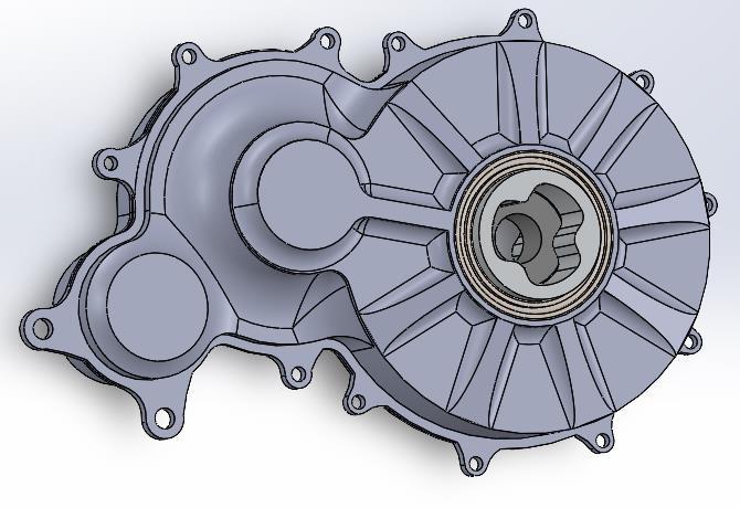
Inthissection,wedelveintothedetailedanalysisofthe two-stagereductiongearboxdesignedfortheFormula ElectricVehicle(FEV).Theprimaryobjectiveofthis analysisistoensurethegearbox'sstructuralintegrity, efficiency,andreliabilityundervariousoperating
International Research Journal of Engineering and Technology (IRJET) e-ISSN: 2395-0056
Volume: 11 Issue: 07 | July 2024 www.irjet.net p-ISSN: 2395-0072
conditions.Advancedsimulationtechniques,particularly usingANSYSsoftware,areemployedtoperform comprehensiveFiniteElementAnalysis(FEA)onthe gearboxcomponents.Thisanalysisincludesassessingthe stressdistribution,deformation,andfatiguelifeofthe gearsandassociatedparts.
Thisdesignreportoutlinestheanalysisandvalidationof anEN24steelgearsystemusingANSYSsimulation.The gearsystemcomprisesadrivergearwith18teethanda drivengearwith42teeth.Theprimaryobjectivesofthe analysisweretodeterminethemaximumstressandthe factorofsafety(FOS)underspecifiedoperational conditions.
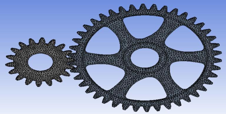
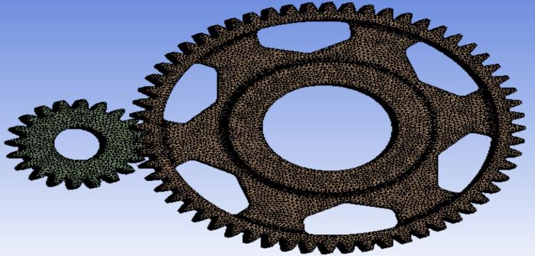
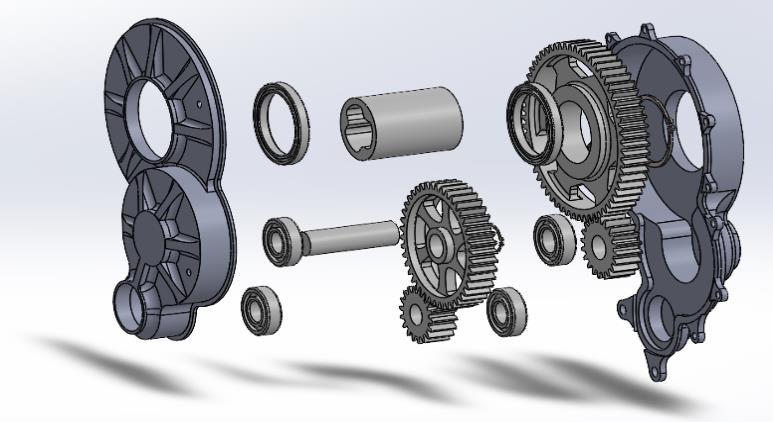
3.1.1 Geometry and mesh
1) Gear Details:
a) Driver Gear1:18teeth
b) Driven Gear2:42teeth
c) Driver Gear3:20teeth
d) Driven Gear4:60teeth
2) Mesh Size:1mmelementsize
3) Mesh Type:High-qualitytetrahedralmeshfor accuratestressdistributionandcontactsimulation.
4) Statistics For 1st Stage:
a) Node:555083
b) Elements:348871
5) Statistics For 2st Stage:
a) Node:653831
b) Elements:383191
3.1.2 Boundary Conditions
1. Driver Gear 1 and Gear 3:
o Rotational Velocity:3000RPMapplied tosimulateoperationalspeedforgear1 and1287RPMforGear3.
o Moment:120Nmtorqueappliedtothe drivingshaftforgear1and280Nmfor Gear3.
o Support:Remotedisplacementallowing freerotationaroundthex-axis.
2. Driven Gear 2 and Gear 4
o Support:Cylindricalsupportappliedto simulaterealisticboundaryconditions withoutrestrictingrotationalmovement.
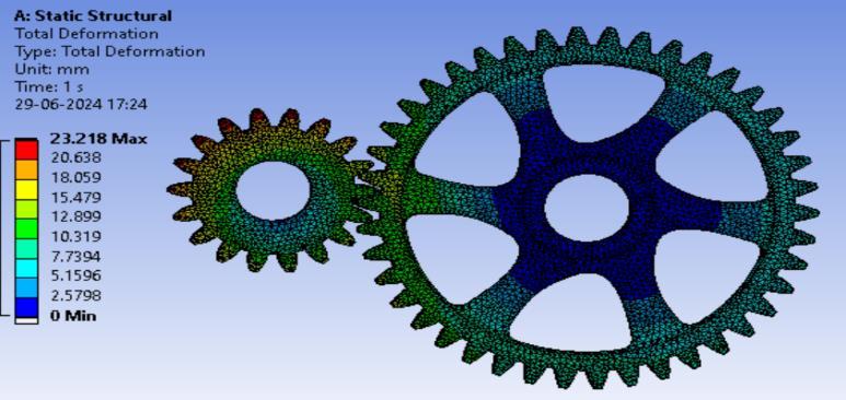
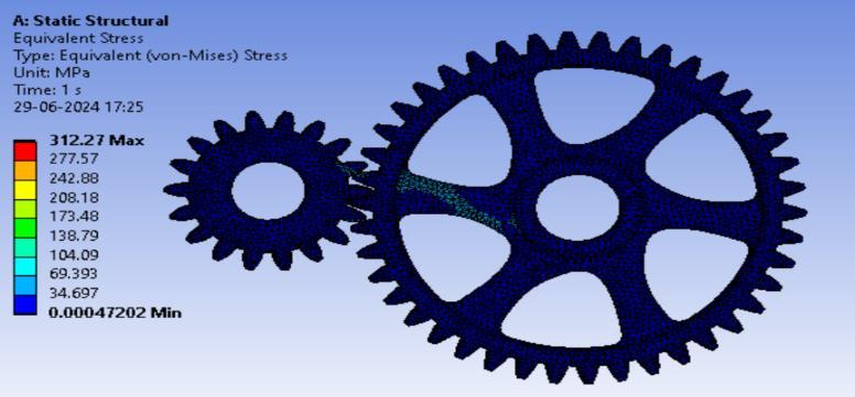
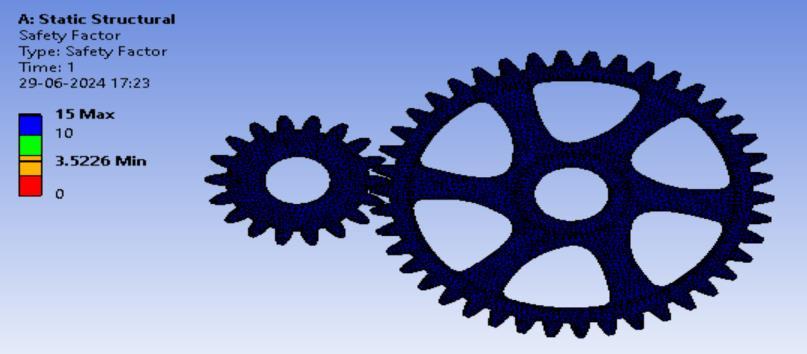
3.1.3 Results
International Research Journal of Engineering and Technology (IRJET) e-ISSN: 2395-0056
Volume: 11 Issue: 07 | July 2024 www.irjet.net p-ISSN: 2395-0072
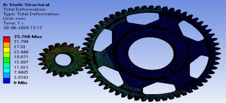
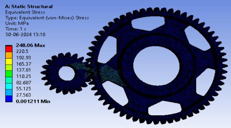
• Maximum Stress:312MPa,observedatthegear teethcontactpointsin1st Stageand248MPain 2nd Stage
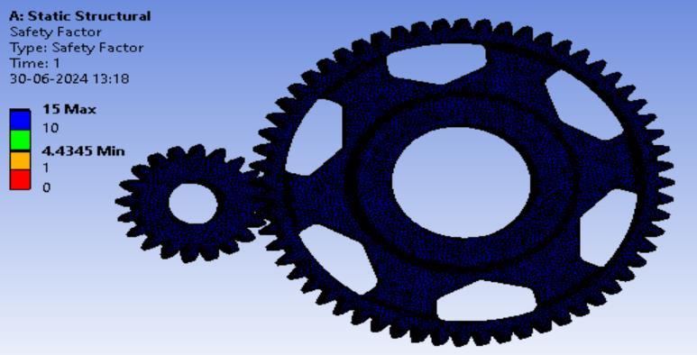
• Factor of Safety (FOS):3.5in1st stageand4.4in 2nd stage,indicatingthedesignissafeandmeets therequiredsafetymargin.
• Theanalysisdemonstratesthatthegearscan withstandtheappliedloadswithasufficient safetymargin,ensuringreliableperformancein operationalsettings.
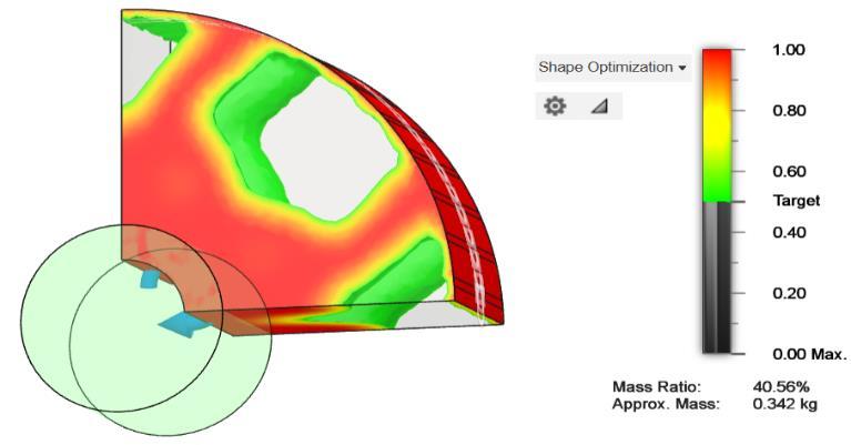
Inthissection,wefocusontheoptimizationofthespur gearsusedinthetwo-stagereductiongearboxforthe FormulaElectricVehicle(FEV)utilizingAutodeskFusion 360.Thegoalofthisoptimizationprocessistoenhance theperformance,efficiency,anddurabilityofthegearbox byrefiningthegeardesign.
International Research Journal of Engineering and Technology (IRJET) e-ISSN: 2395-0056
Volume: 11 Issue: 07 | July 2024 www.irjet.net p-ISSN: 2395-0072
3.2.1 Optimization Parameters:
Parameter Gear1&Gear2 Gear3&Gear4
3.2.2 Process Overview:
1. Modeling and Initial Design:
o Theinitialspurgearmodelsarecreated inFusion360,incorporatingthebasic designparametersandconstraints.
2. Simulation Setup:
o Operationalconditionsandmaterial propertiesaredefined,andstatic structuralanalysisisperformedto identifystressdistributionandpotential deformation.
3. Optimization Iterations:
o UsingFusion360’soptimizationtools, multipleiterationsareconductedto refinethegeargeometry.Thisinvolves adjustingparameterssuchasthenumber ofteeth,facewidth,andpressureangleto achievethedesiredbalancebetween strengthandweight.
4. Dynamic Simulation:
o Theoptimizedgeardesignisthen subjectedtodynamicsimulationsto assessitsperformanceunderrealistic operatingconditions,includingvarying loadsandspeeds.
5. Fatigue Analysis:
o Fatiguelifepredictionsarecarriedoutto ensurethegearscanwithstand prolongedusagewithoutfailure,focusing onareaspronetohighstressandcyclic loading.
6. Validation:
o Thefinaloptimizeddesignisvalidated throughacomprehensivereviewofthe simulationresults,ensuringall performancecriteriaandconstraintsare met.
TheuseofFusion360forgearoptimizationenablesa streamlinedandefficientdesignprocess,resultingina high-performancegearboxtailoredfortherigorous demandsofFormulaElectricVehicleracing.Theinsights gainedfromtheoptimizationprocesscontribute significantlytotheoverallenhancementofthegearbox design.
In this paper, the design and analysis of a two-stage reduction gearbox for a Formula Electric Vehicle (FEV) were presented, with a specific focus on utilizing EN24 materialforitscomponents.Thedesignaimedtomaximize power transmission efficiency while minimizing weight and spatial footprint, essential for high-performance electric racing. By selecting appropriate gear ratios and conducting a detailed structural analysis using Finite Element Analysis (FEA), we ensured the gearbox's durability and reliability under operational stresses. Material properties of EN24,suchas high tensile strength andexcellentfatigueresistance,werecrucialinachievinga robust and efficient gearbox design. The final design demonstrated significant improvements in torque amplification and speed reduction, contributing to the overall dynamic performance of the FEV. This study provides a comprehensive approach to gearbox design, offeringvaluableinsightsintoachievinghighefficiencyand robustness in electric vehicle applications. The successful implementation of this two-stage reduction gearbox underscoresits potentialto enhancethecompetitiveedge andperformanceofFormulaElectricVehicles.
[1] Norton, R. L. (2006). Machine Design: An Integrated Approach.PrenticeHall.Pages:650-670
[2] Budynas, R. G., & Nisbett, J. K. (2011). Shigley's Mechanical Engineering Design. McGraw-Hill Education. Pages:472-500
[3] Mott, R. L. (2013). Machine Elements in Mechanical Design.Pearson.Pages:520-540
[4] Doughty, S., & Vallance, A. (1999). Design of Machine Elements.TataMcGraw-Hill.Pages:310-330
[5] Juvinall,R.C.,&Marshek,K.M.(2011). Fundamentalsof Machine Component Design.JohnWiley&Sons.Pages: 425-450
[6] Spotts, M.F., &Shoup, T.E. (2004). Design of Machine Elements.Pearson.Pages:400-420
[7] Collins,J.A.,Busby,H.,&Staab,G.H.(2010).Mechanical Design of Machine Elements and Machines: A Failure PreventionPerspective.JohnWiley&Sons.Pages:370390
[8] Hamrock,B. J., Schmid, S. R., & Jacobson, B. O. (2013). Fundamentals of Machine Elements. McGraw-Hill Education.Pages:500-520
[9] Gopinath, K., & Shanmugham, M. S. (2014). Machine Design.AnuradhaPublications.Pages:260-280
[10] Bhandari, V. B. (2010). Design of Machine Elements TataMcGraw-Hill.Pages:550-570
[11] Jung,D.(2018). GearDesignSimplified.IndustrialPress. Pages:180-200