
International Research Journal of Engineering and Technology (IRJET) e-ISSN:2395-0056
Volume: 11 Issue: 07 | July 2024 www.irjet.net p-ISSN:2395-0072

International Research Journal of Engineering and Technology (IRJET) e-ISSN:2395-0056
Volume: 11 Issue: 07 | July 2024 www.irjet.net p-ISSN:2395-0072
Manish V. Mehta1,2, Mrunalkumar D. Chaudhari3* , Jay J. Vora4*
1Research Scholar, Gujarat Technological University, Ahmedabad, India,
2Government Polytechnic, Rajkot, India.
3Mechanical Engineering Department, L. D. College of Engineering, Ahmedabad, India
4Mechanical Engineering Department, Pandit Deendayal Energy University, Gandhinagar, India
Abstract:
Shielded Metal Arc welding with ENiCrMo-10 weld cladding on Grade 316L austenitic stainless steel is examined in this article. This material-process combination is being evaluated for use in petrochemicals, oil, gas, medicines, and chemical processing plants. The weld cladding was assessed through a series of examinations, counting visual inspection, micro hardness,chemicalcompositionstudyviaopticalspectroscopy,bendtestsand Corrosionresistancetesting,whilemacroand microstructure observations provided additional insights. These observations show numerous remarkable results. A large dilutionheightof3.0mmfromthebasemetalenabledprecisecontrolandminimumalloymixing.Visualinspectionandbend testsconfirmed cladding weldintegrity. The weld cladding'shigh-qualityfinish eliminatestheneedforcostlymachiningand polishing, saving money. The study clarifies main and secondary inter-laminar spacing, improving structural integrity. Weld claddingtoughnessisalsogood.Theweldcladding'slowcorrosionresistancemustbenoted.Thisresearchintroducesanew material combination and highlights its many benefits for industry stakeholders, notably in the petrochemical and pharmaceutical industries. It improves welding operations and improves industrial applications' efficiency, cost, and structuralperformance.
Key words: ENiCrMo-10,ShieldedMetalArcWelding(SMAW),Grade316L,Weldcladdingperformance
1. Introduction:
The manufacturing industries like chemical, petrochemical, pharmaceutical and oil & gas play a important role in the world economy. They supply variety of materials and products related to chemicals are necessary for numerous region, including energy, manufacturing, and transportation [1]. A major challenge for industries is the corrosive degradation of equipment surfaces. This problem is triggered by wear and corrosive substances that contaminate various parts of manufacturingequipment[2][3].Degradationcanresultfromerosion,corrosion,or /andfriction,eitherindependentlyorin combination, and is influenced by parameters To address this issues, a practical preventive measure includes applying protectivecoatingsmadefromspecializedcorrosion-resistantmaterials,considerablyreducingdegradationofmanufacturing equipment[4]–[9].
Responding to rising requirement for surface protecting materials across a variety of applications necessitates inventive resolutions that enhance material life, efficiency, and consistency. So, selecting appropriate protective layers becomes important for ensuring safe operations. Among the effective methods garnering considerable attention are weld cladding techniques,whichimprovecorrosionresistanceofparentmaterials[10],[11].
Weld cladding, a specific technique for enhancing corrosion resistance, plays a important role in safeguarding critical infrastructure and equipment from aggressive environments. This process entails depositing a layer of corrosion-resistant alloyontoabasemetalthroughwelding.Theprimary benefitofthismethodliesinitscapacitytocreateaprotectivecoating that insulates the underlying material from corrosive agents, including acids, chemicals, and saltwater. By employing weld cladding, industries can significantly extend the operational life of their assets, thereby reducing the frequency of replacementsandminimizingmaintenancerequirements.Thistechniqueoffersastrategicapproachtocorrosionprevention, allowing for the targeted application of protective materials to high-risk areas. As a result, it presents a more economical alternative to constructing entire structures from costly corrosion-resistant alloys. The implementation of weld cladding techniques contributes substantially to the overall resilience, longevity, and economic efficiency of industrial equipment and
International Research Journal of Engineering and Technology (IRJET) e-ISSN:2395-0056
Volume: 11 Issue: 07 | July 2024 www.irjet.net
p-ISSN:2395-0072
infrastructure.Bymitigatingthedetrimentaleffectsofcorrosion,thismethodensuresimprovedperformanceandreliabilityin challengingoperationalenvironments[12]–[14].
During the weld overlay process, a phenomenon known as welding dilution takes place. This occurs when the heat generated by welding causes the base material to partially melt and intermix with the added filler metal. Welders typically select filler materials for their specific attributes, such as enhanced durability or resistance to corrosive elements. As the intenseheatofweldingisapplied,itnotonlymeltsthefillermetalbutalsocausessomemeltingofthebasemetalatthe joint interface. The resulting blendof baseandfiller metalsinthe weld pool is whatconstitutes welding dilution. Thisinteraction between the two metals can significantly influence the properties of the final weld, particularly in the area where the weld meetsthebasemetal.
Thelevelofdilutiondependsonfactorssuchastheweldingprocess,weldingparameters(current,voltage,travelspeed), filler metal type, and metallurgical properties of the base metal. Excessive dilution can lead to changes in mechanical propertiesandcorrosionresistance,potentiallyaffectingperformanceandintegrity.Therefore,controllingweldingdilutionis essential to ensure welds meet the required specifications and maintain desired properties. Skilled welders and proper techniques are employed to manage dilution and achieve consistent, predictable weld characteristics. In critical applications where minimizing dilution is necessary, specialized welding processes and techniques may be used to control the mixing of basemetalandfillermetalmoreeffectively[4],[15],[16].
Weldcladdingisatechniqueemployedtoenhancethesurfacecharacteristicsofaparentmaterialbydepositingasuperior metal layer through specialized welding methods. To ensure high-quality results in weld cladding, it's crucial to evaluate severalgeometricaspectsoftheweldbead.Theseincludeits verticalprofile,horizontalspan,additionalbuildup,penetration, and the extent to which adjacent beads overlap. These measurements are essential in determining the level of dilution - a concept that quantifies the degree of mixing between the original base metal and the added cladding material during the weldingprocess.Inessence,dilutionindicateshowmuchtheunderlyingmetalintegrateswiththenewlyappliedlayerasthey melt and resolidify together. Understanding and controlling dilution is vital for achieving the desired properties in the clad surface, as it directly influences the final composition and performance of the welded area. By carefully managing these parameters, welders can optimize the cladding process to effectively improve the surface qualities of the base metal while maintainingtheintendedcharacteristicsofthecladdingmaterial[17]–[20].
Of the many cladding materials available, ENiCrMo-10 is notable for its high-performance properties as a Ni-Cr-Mo-W alloy. The ENiCrMo-10 alloy, when used for weld cladding, demonstrates exceptional resistance to a broad spectrum of corrosive conditions. Its protective qualities extend to both oxidizing and reducing acidic environments, making it an ideal choice for applications in challenging industrial settings. This alloy finds particular utility in sectors such as chemical processing,petrochemicaloperations,andpharmaceuticalproduction,wherematerialsareexposedtoharshchemicalagents. The primary benefit of applying ENiCrMo-10 through weld cladding lies in its ability to significantly boost the corrosion resistanceoftheunderlyingmetal.Bydepositingthisalloyontothesurfaceofabasematerial,aprotectivebarrierisformed. This layer effectively shields the base metal from the destructive effects of various corrosive substances, including acids, alkalinecompounds,andchloride-containingsolutions.Inenvironmentswherethebasemetalwouldtypicallybesusceptible tocorrosiveattack,theENiCrMo-10claddingprovidesacruciallineofdefense.Thisprotectivefunctionisespeciallyvaluable in industrial applications where material integrity is paramount for safety, efficiency, and longevity of equipment and structures[21]–[24]
ENiCrMo-10weldcladdingoffersseveraladvantages,thoughitalsopresentsuniquechallenges.Thedistinctmetallurgical characteristics of ENiCrMo-10, when compared to common base materials such as austenitic stainless steel or low carbon steel, can lead to complications in creating a robust, flawless weld interface between the substrate and the cladding layer. These differences in material properties often necessitate specialized welding techniques and careful control of welding parameterstoensureasuccessfulcladdingapplication[25]–[30].Thesechallengesstemfromvariationsinthermalexpansion coefficients and melting points [24], [31], [32]. The application of ENiCrMo-10 cladding demands meticulous consideration whendeterminingweldingvariables,selectingappropriateconsumables,andchoosingsuitabletechniquestocreateadurable and reliable connection between the materials. During the cladding process, ENiCrMo-10 may be susceptible to issues like solidification cracking and hot cracking, especially if suboptimal practices are employed. These problems can arise from factorssuchasexcessiveheatinputorinadequatesurfacepreparation.
International Research Journal of Engineering and Technology (IRJET) e-ISSN:2395-0056
Volume: 11 Issue: 07 | July 2024 www.irjet.net p-ISSN:2395-0072
To minimize the occurrence of these complications, it's essential to implement several key strategies. These include utilizing compatible filler materials, implementing precise heat input control measures, ensuring thorough cleaning procedures, Maintaining appropriate interpass temperatures. By adhering to these best practices, welding professionals can significantlyenhancethequalityandintegrityofENiCrMo-10claddingapplications[33],[34].
Selecting a process for weld cladding entails considering several key factors for a successful and high-quality result. Materialcompatibilityiscrucialtoavoidissueslikecrackingandincompatibilitybetweenthebaseandcladdingmaterials.The choice of cladding material should align with desired properties. Determining the required weldoverlay thickness and managingdilutionareessentialforachievingthedesiredpropertiesanddimensions.Thejointconfigurationmustbeassessed toselectaweldingprocesssuitableforthespecificgeometryandaccessibility. thicknessinfluencesthechoiceof thewelding process, withthicker materialsfavoring submergedarc orflux-cored arc welding, andthinner materialssuiting gasmetal or tungsten arc welding. Other considerations include required quality, production rate, heat input, accessibility, operator skill, equipmentavailability,andcost.Commonweldingprocessesforweld claddingincludeGMAW/MIG,GTAW/TIG,SMAW,SAW, FCAW,andPTAW.Thefinalselectionshouldresultfromacomprehensiveassessmentofthesefactorstoensureadurableand successfulweldcladdingfortheintendedapplication.
Choosingthemostsuitableweldingprocessforweldcladdingisakeydecisionthatinvolvesbalancingmultiplefactorsto achieve the best results, reduce dilution, and capitalize on the deposition rate. Conventional welding process like SMAW, GTAW, MIG/MAG and SAW are frequently used for tasks such as filling back welding. Among these, SMAW is especially common in smaller and medium-sized industries, though every method has its respective benefits and limitations Various welding techniques offer different advantages and drawbacks when applied to cladding processes. Traditional methods like ShieldedMetalArcWelding(SMAW)andGasTungstenArcWelding(GTAW)typicallyresultinslowermaterialdeposition.On theotherhand,MetalInertGas/MetalActiveGas(MIG/MAG)procedures,whilepotentiallyfaster,mayintroduceissuessuch asexcessivespatter,suboptimalsurfacefinish,andincreaseddilutionrates.
Submerged Arc Welding (SAW) stands out for its ability to deliver high heat input and achieve deeper penetration. However, more advanced technologies have emerged to address specific cladding challenges. These include Cold Metal Transfer (CMT), Hot Wire Technology (HWT), laser cladding, and Plasma Transferred Arc Welding (PTAW). These cuttingedge methods offer several benefits like enhanced control over dilution, accelerated deposition speeds, superior overall claddingquality.It'simportanttonotethatwhiletheseadvancedtechniquescanyieldimprovedresults,theyoftencomewith higherequipmentcostsandrequireoperatorswithspecializedskillsandtraining[35]–[37].
SMAWpresentsseveraladvantagesforweldcladdingapplicationscomparedtobothconventionalandadvancedwelding techniques.Itsversatilityallowsforuseinvariouspositionsandenvironments,makingitsuitableforscenarioswhereaccess is limited or the workpiece is difficult to maneuver. Moreover, SMAW equipment is portable and straightforward, offering a cost-effectivesolutionforon-siteapplicationsandrepairs.Itssimplicityalsomakesitaccessibletoa widerrangeofwelders, reducingtrainingcostsandtime[67]
Anothersignificantadvantage ofSMAWfor weld claddingisitsability to work well with dirtyorrusty materials,asitis less sensitive to surface contaminants compared to other welding processes. Additionally, SMAW eliminates the need for external shielding gas, as the flux-coated electrode generates its shielding gas when burned. This feature makes SMAW ideal foroutdoororremoteapplicationswheregasavailabilitymaybelimited.WhileSMAWprovidesgoodpenetrationandfusion for strong welds, When determining the most suitable welding process for a weld cladding application, it is important to assessfactorssuchasthethicknessofthematerialsinvolved,theweldingposition,andtheavailableprojectbudget.[65]-[66].
In current times, a noticeable rise in the use of ENiCrMo-10 weld cladding on Grade 316L in numerous industries, particularly in petrochemicals. This rise in popularity can be attributed to the demand for materials capable of withstanding highly corrosive conditions, maintaining structural integrity, and reducing maintenance expenses. This work aims to underwritetopresentinformationandofferappreciatedinsightsintothesuccessfulapplicationofENiCrMo-10weldcladding onGrade316Linindustrieslikepetrochemicals,oilandgas,pharmaceuticals,andchemicalprocessing.
Cracks in welds between dissimilar materials have been identified in numerous plants, and there are many documented instances of failures in weldments involving different alloys. Hot cracking defects are frequently seen in dissimilar material weldingduetothermalcontractionsfromunequalheatingandcoolingratesduringtheweldingprocess.Asaresult,research
International Research Journal of Engineering and Technology (IRJET) e-ISSN:2395-0056
Volume: 11 Issue: 07 | July 2024 www.irjet.net p-ISSN:2395-0072
has been directed at finding ways to evaluate and repair structural integrity. To control crack growth and enhance weld thickness and corrosion resistance, shielded metal arc welding (SMAW) is commonly used for cladding. Manual SMAW claddingisespeciallysuitableforrepairandmaintenanceofcriticalareasduetoitsversatility[64]-[66].
Toachievethisobjective,theresearchpaperfocusesoninvestigatingtheGasTungstenArcweldingprocessforapplying ENiCrMo-10weldcladdingonGrade316L.Arangeoftestingmethodswillbeappliedinthisstudy,includingvisual test(VT) andmicrohardnesstests,sidebendtesting,andchemicalcompositionanalysis.ThePotentiodynamicPolarizationTechnique willbeusedforcorrosionresistanceevaluation,andtheresearchwillalsoincludeobservationsofmacroandmicrostructures andananalysisofdilution
Theoutcomesofthisresearchholdsignificantimportanceforthevariouscritical industrial applications,astheyprovide valuable insights into effectively applying ENiCrMo-10 weld cladding on Grade 316L. The findings can lead to improved material performance, cost-effectiveness, and reliability in critical industrial environments. Moreover, the study aligns with the growing trend of utilizing ENiCrMo-10 weld cladding on Grade 316L, making it a precious source for researchers and industryprofessionalsintheareaofmaterialsengineering.
In this investigation, the SMAW method used to experimentally deposit ENiCrMo-10 flux-coated solid filler wire onto AusteniticstainlesssteelGrade316L.Thestudyaimedtoevaluatethe fitnessofthisweldingmethods andmaterialgrouping forapplicationinpresentindustrialcontexts
2.1 Material
ENiCrMo-10 alloy was applied to Grade 316L steel using the SMAW methods. Table 1 displays the nominal chemical compositionsofbothHastelloyC-22andGrade316Lsteel.
Table1.NominalChemicalComposition(Wt.%)forGrade316LAusteniticStainlessSteelandENiCrMo-10AlloyinthePresent Work
The material under investigation in this study was Grade 316L, with a thickness of 10mm. Its nominal chemical compositionisdetailedinTable1.PlatesofGrade316Lwerepreciselycutandmachinedtodimensionsof500mmx300mmx 10mm.
2.2 Method
In the current research endeavor, The SMAW process is employed to apply Hastelloy Mo-10 alloy weld cladding onto Grade316L,tocapitalizeonthemanifoldbenefitsthisprocessoffers.Initially,atotalof5bead-on-platetrialswereconducted tometiculouslyselectandscreenweldingparameterssuitableforthisresearch.Thechoiceofparametersforthesetrialswas guidedbytherecommendationsprovidedbytheconsumablemanufacturer,insightsgleanedfromliteraturesurveys,andthe wealthofindustrialexperiencewiththisprocess[25],[37],[38],[47],[52] Thisresearchprojectinvolvedconductingaseries ofindividualweldingpassesonabead-on-platesetup.Theexperimentwasrepeatedfivetimestoensurereliabilityofresults. The primary objectives were to examine the operational aspects of the welding process and to investigate how variations in
International Research Journal of Engineering and Technology (IRJET) e-ISSN:2395-0056
Volume: 11 Issue: 07 | July 2024 www.irjet.net p-ISSN:2395-0072
welding energy influenced specific geometric features of the weld bead. The key characteristics under scrutiny included the height of the weld reinforcement, the ratio between reinforcement height and bead width, the extent of dilution occurring during the welding process. By focusing on these parameters, the study aimed to provide insights into the relationship betweenweldingenergyinputandtheresultingweldbeadgeometry.
Theoptimaloperatingparameterswereestablishedthroughacombinationofdilutionanalysisandvisualinspections ofthebead-on-platespecimens.Theseparametersweresubsequentlyappliedtoweldingcoupons,asillustratedinFigure1.
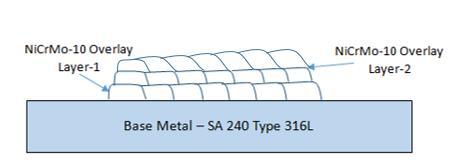
Proper melting and strong adhesion, particularly at the vertex, must be ensured by the process parameters, while preventingexcessivedilutionandavoidingdefectsduetorapidcooling.ShieldedMetalArcWeldingprocesswasusedtoapply three layers of ENiCrMo-10 weld cladding to the Grade 316L base plate. Each layer included ten welding beads. Table 2 outlinesthepertinentprocessparameters,includingweldingcurrent,voltage,travelspeed,andotherrelevantfactors.
Inpreparationfortheweldingprocess,thesubstrate'stopsurfaceunderwentthoroughcleaningwithethylalcoholto removeanycontaminants.Theteamthenemployedthe ShieldedMetalArcWelding(SMAW)techniquetoapply threelayers ofHastelloyMO-10alloyweldcladding,resultinginaninitialthicknessofapproximately7mmforboththesubstrateandthe deposited layer. Post-welding visual inspection revealed uniformly smooth welds without noticeable defects. To further ensurequality,non-destructivetestingwasconducted,focusingonidentifyingpotentialissuessuchascracks,discontinuities, and interface defects in the cladding. This comprehensive approach aimed to verify the integrity and soundness of the weld claddingapplication,ensuringthatthefinalproductmettherequiredstandardsforperformanceandreliability.
2.2.1 Bend test
Bend testing serves as a crucial evaluation method for Hastelloy weld claddings, offering key insights into their performancecharacteristics.Thistechniquesubjectsthecladdingtospecific bendingstresses,allowingfortheassessmentof
International Research Journal of Engineering and Technology (IRJET) e-ISSN:2395-0056
Volume: 11 Issue: 07 | July 2024 www.irjet.net p-ISSN:2395-0072
its flexibility, durability, and overall structural soundness. By doing so, it helps identify potential defects or weak points that might not be apparent through other inspection methods. The process also verifies compliance with industry-specific standards, ensuring that the cladding meets the stringent requirements of its intended applications. For manufacturers and end-users alike, bend testing provides a reliable means to gauge the cladding's ability to withstand operational demands, thereby confirming its suitability for use in challenging industrial environments. This comprehensive approach to quality assurancecontributessignificantlytotheconfidenceinthelong-termperformanceandreliabilityofHastelloyweldcladdings [20], [27], [53]. The reliability assessment of the welded cladding, particularly focusing on the cladded layers, involved subjecting two specimens to side edge bend tests in accordance with BS EN ISO 5173:2010/A1:2011 standards. This comprehensive evaluation targeted ENiCrMo-10 Hastelloy MO-10 weld cladding applied to Grade 316L material using the SMAWprocess.Thetestingregimenaimedtothoroughlyexaminethecladding'sweldability,ductility,structuralintegrity,and overallquality.UtilizingaDigitalUniversalTestingMachine(modelUTE-60)manufacturedbyFIE,thebendtestswerecarried out meticulously. The results of these tests successfully met the acceptance criteria outlined in BS EN ISO 15614-7:2019, providing strong evidence of the cladding's performance capabilities and its adherence to industry standards. This rigorous testingapproach ensuresthatthe welded cladding meetsthe stringent requirements necessaryforitsintendedapplications, offeringconfidenceinitsreliabilityanddurabilityundervariousoperationalconditions.
Evaluating the mechanical properties and integrity of Hastelloy MO-10 weld claddings relies heavily on hardness testing. This method offers crucial insights into the material's quality, the integrity of the weld, the heat-affected zone's characteristics,adherencetoacceptancestandards,andqualitycontrolprocedures.[37],[54],[55].
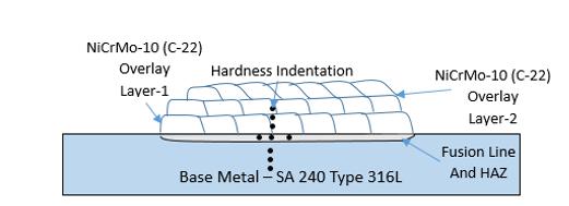
To verify the mechanical properties of the weld cladding and ensure its suitability for the intended application, a seriesofhardnesstestswereperformed.The evaluationprocessinvolved examiningtransversecross-sectionsofthewelded specimens using a Leco Vickers hardness tester (Model: M-400A). Hardness measurements were taken at multiple strategic points,encompassingtheweldarea,heat-affectedzone,andbasemetal,employinga1000gfload.Thiscomprehensivetesting approach, conducted in accordance with EN ISO 9015-1:2011 standards, provided a detailed hardness profile across the various regions of the welded specimen. The specific locations of the hardness testing points were clearly illustrated in the accompanying Figure 2, offering a visual representation of the test methodology. By systematically assessing the hardness distribution,thisanalysishelpstoconfirmtheoverallintegrityandperformancecharacteristicsoftheweldcladding,ensuring itmeetstherequiredmechanicalspecificationsforitsintendeduse.
2.2.3
Conducting a thorough evaluation of Hastelloy MO-10 overlays on Grade 316L stainless steel is crucial for determining weld integrity, detecting flaws, and verifying adequate bonding and penetration depth. This analysis is vital to ensure the cladding meets quality standards and performs as intended in corrosive environments [2], [56]. Conducting a detailed inspectionis crucial for evaluatingthedurabilityanddependability oftheoverlaywelding.Thisprocessplays a key roleinimprovingtheoverallfunctionalityandlifespanoftheweldedconnection
International Research Journal of Engineering and Technology (IRJET) e-ISSN:2395-0056
Volume: 11 Issue: 07 | July 2024 www.irjet.net p-ISSN:2395-0072
The macroscopic analysis involved cutting AISI 316L plates with Hastelloy MO-10 cladding, originally 500x300x10 mm,intosmaller10x300x10mmsamples.Thesewerethensubjectedtoaprogressivepolishingregimenusingsiliconcarbide abrasive papers of increasing fineness (120, 320, 400, and 600 grit), followed by alumina powder polishing. The specimens weresubsequentlyetchedwithKalling'sreagent.ExaminationwascarriedoutusingaMetlabStereoZoomMicroscopeat10X magnification.
Microstructural investigation is essential for evaluating key material properties including tensile strength, hardness, malleability, and resistance to corrosion. It reveals crucial information about grain morphology, phase composition, and the presenceofanystructuralimperfectionsorprecipitatesthatcouldaffectmaterialbehavior.Thisresearchalsodelvesinto the characteristics of grain boundaries, phase distribution patterns, and the role of alloying elements in enhancing corrosion resistance[5],[8],[38],[55].
To conduct microstructural examination of the Hastelloy overlay welds, specimens measuring 10x300x10 mm were further reduced to 20x10x10 mm using a precision micro wire electrical discharge machining (EDM) process. These smaller samples underwent a meticulous surface preparation sequence. This involved progressive grinding with silicon carbide abrasivesofincreasingfineness,startingat120gritandproceedingthrough320,400,600,800,1000,and1200grit.Thefinal polishing stages utilized alumina powder and diamond paste to achieve a mirror-like 1 μm surface finish. A Metlab optical microscopewasthenemployedtoinvestigatethemicrostructuralfeaturesacrosstheweldoverlay,heat-affectedzone(HAZ), andsubstratematerial.
The spacing of primary and secondary dendrites in weld claddings is a key microstructural parameter that affects mechanical strengthandcorrosionresistance.Irregularitiesorvariationsin dendritespacing maysuggestissuessuchashot cracking, lack of fusion, or defects due to the solidification process, potentially compromising weld quality. This research analyzedprimaryandsecondarydendritespacingsinHastelloyMO-10weldcladdingsonGrade316LusingtheShieldedMetal Arc Welding (SMAW) technique, with detailed observations and measurements made using the Olympus DSX-1000 digital microscope.
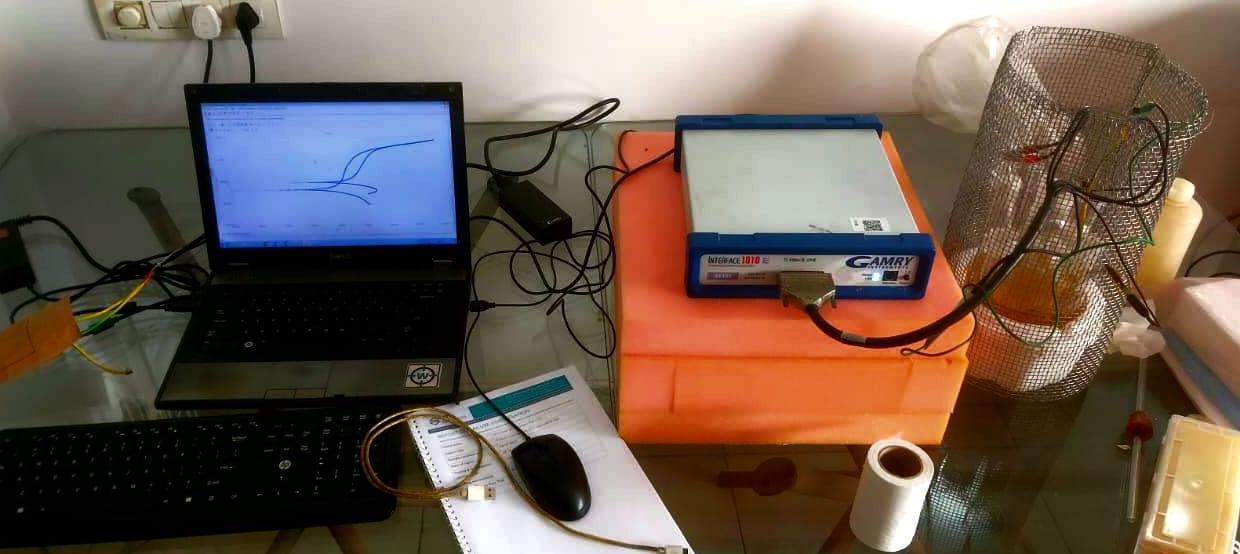
The Potentiodynamic Polarization method is employed to evaluate the corrosion resistance of various materials, including Hastelloy MO-10. This electrochemical technique provides crucial data on the corrosion behavior of Hastelloy MO10,whichisimportantforselectingappropriate materials,optimizingconditions,andenhancingperformance anddurability in aggressive environments. In this study, clad samples with dimensions of 10mm by 10mm were tested for corrosion resistance in a ferric sulfate and sulfuric acid solution, with the Gramy Interface 1010E potentiostat used for the corrosion analysis.
International Research Journal of Engineering and Technology (IRJET) e-ISSN:2395-0056
Volume: 11 Issue: 07 | July 2024 www.irjet.net p-ISSN:2395-0072
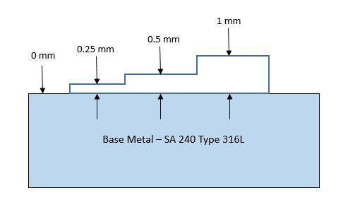
Optical spectroscopy is a vital method for analysing the chemical composition of weld cladding samples, which ensuresmaterialquality,consistency,andperformanceincorrosiveenvironments.Thisanalysishelpsverifythatthecladding provides reliable and long-lasting protection. In this study, chemical composition was studied by an optical spectroscopy device by Hitachi Foundry Master Pro-2, with samples analysed at different thicknesses as demonstrated in Figure 3. The sample removal process adhered to ASME Section 9 Figure QW-462.5(a), and testing was performed according to ASTM E3047-16standards.
3. Results and discussion
3.1
Upon visual inspection, both the Austenitic Stainless Steel 316L and Hastelloy Weld cladding exhibited impeccably clean surfaces without any discernible welding imperfections. Notably, there were no indications of spatter, undercutting, porosity,lackoffusion,inclusions,orcracks,aligningwiththeexpectedoutcomesdescribedintheliteratureandhighlighting Hastelloy's commendable weldability [6], [50], [51]. However, there remains a gap in our understanding regarding the reactionof theENiCrMo-10 weldcladding to fusionand solidification ratesinherent in welding processes, particularlywhen utilizingtheShieldedMetalArcWelding(SMAW)technique.TheuppersurfaceoftheENiCrMo-10weldcladding,appliedonto an SS-316L substrate, is depicted. Notably, the Hastelloy weld cladding displays a flawless surface, devoid of any welding imperfectionssuchasspatter,undercutting,porosity,lackoffusion,inclusions,cracks,orotherirregularities.
The welding conditions utilized in this investigation have directly influenced the quality of the claddings. The exceptional quality of the cladding material is intricately linked to the precise selection of welding parameters. Critical elementscontributingtothisqualityencompassproficientweldingtechniquesandensuring anappropriatelateraloverlapof each pass. The surface quality of the cladding is deemed satisfactory due to the inherent geometric uniformity across the coatedarea,theabsenceofflaws,andtheminimaloccurrenceofsplattering,allindicativeofahighstandardofcraftsmanship.
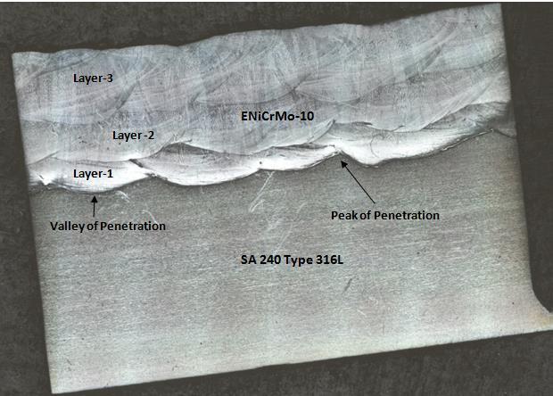
The material underwent a macroscopic examination at 10x magnification, as shown in Figure 4. The sample was macro-etched, visually inspected, and subsequently magnified 10 times under a microscope. This process facilitated the examinationofthecross-sectionoftheHastelloyMO-10weldcladdingonausteniticstainlesssteel316L.
International Research Journal of Engineering and Technology (IRJET) e-ISSN:2395-0056
Volume: 11 Issue: 07 | July 2024 www.irjet.net p-ISSN:2395-0072
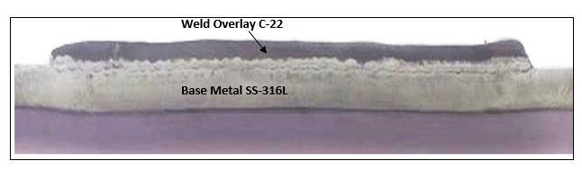
Figure 4 presents a cross-sectional view of the weld cladding and the base metal, demonstrating the absence of welding defects. Additionally, the cross-section highlights minimal penetration of the Hastelloy weld cladding into the base metal, a characteristic often associated with the heat input inherent in the SMAW process [37], [40], [49], [59]. The line depictedinthefiguredelineatestheextentofpenetrationoftheweldcladdingmetalintothebasemetal.
To assess the reliability and weldability of the procedure, we implemented the optimal parameters derived from previoustests on actual samplesof weld cladding. In this studyaimed at enhancingproductioncost efficiency, we employed AISI 316 L SS cladding with two layers of Hastelloy MO-10. Our primary goal was to ascertain whether these parameters wouldyield welds devoidof typical issuessuchasholesorcracksfrequently encounteredin weld cladding.Additionally,we scrutinized for any indications of excessive hardening in the cladding layer or insufficient integration between the cladding layerandtheAISI316LSSsubstrate.
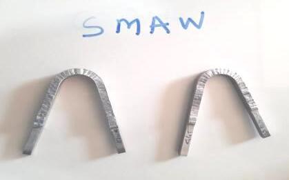
AccordingtoAWSguidelines,defectslargerthan3mm, suchasholesorcracks,shouldnotbepresent,regardlessof orientation, even if the specimenprepared for bending is on the surface orside.Figure5 illustratesthat no cracksappeared anywhere on the specimen during the two instances of the side bend test using universal testing equipment. These results offerevidencethattheparametersusedforthisresearchinweldconditionswerewithoutadoubtoptimal.
International Research Journal of Engineering and Technology (IRJET) e-ISSN:2395-0056
Volume: 11 Issue: 07 | July 2024 www.irjet.net p-ISSN:2395-0072
The Vickers hardness outline of the thick coating's cross-section is outlined in Table 3. The findings can be summarizedasfollows:
The base metal's hardness, notably lower compared to the welding overlay and heat-affected zone (HAZ), remains relatively stable at approximately 206Hv. The weld cladding exhibits an average hardness of about 239Hv. This increase in hardness can be attributed to the evolution of microstructure during the welding process. It is widely acknowledged that microstructure and Vickers hardness are closely linked, with a finer microstructure typically resulting in higher hardness, assuming the phase composition remains constant. Both the HAZ hardness and the interface demonstrate a higher hardness level,approximately256Hv.ThereisanotableincreaseinhardnessobservedfromtheHAZtothecoatinginterface.
Table–3VickerHardnessalongtheHastelloyMO-10weldcladdingonSS-316L
SMAW - Hastelloy Weldcladding - Hardness Study Vicker Hardness Linear (Vicker Hardness)
HAZWeld Interface Weld Overlay Hastelloy MO-10
Base Metal SS - 316L
The Vickers hardness profile of the Hastelloy MO-10 weld cladding on the Grade 316L stainless steel cross-section reveals that the parent metal maintains a constant hardness level at approximately 206Hv. This value is notably lower compared to the hardness levels of the coating and the heat-affected zone (HAZ), which measure 239HV and 256HV, respectively.Thechangesobservedinthesolidifiedmorphologyofthecladdinglayerscanbeattributedtothedilutioneffect, whichdirectlyinfluencesthehardnessofthecladdingweld.
The heat input during the welding process emerges as a significant parameter influencing morphological changes in theweld cladding,particularlywhenthesamecombinationof weld claddingandsubstrateisemployed.Consequently,itcan
International Research Journal of Engineering and Technology (IRJET) e-ISSN:2395-0056
Volume: 11 Issue: 07 | July 2024 www.irjet.net p-ISSN:2395-0072
be inferred that the heat input directly impacts hardness, dilution, and the width of the heat-affected zone. Our ongoing research,alongwithfindingsfromrelevantliterature,supportstheassertionthattheSMAWprocessinvolvessignificantheat input.
The microstructure morphology, influenced by heat input, plays a crucial role in determining the metal's hardness. Moreover,studiesindicate thata notablereductioninthesize of primarydendrites generallyleadstoanincreasein Vickers hardness.Presently, the averagehardnessof theweld claddingslightlysurpassesthemaximum hardness(100 HRB,248Hv) stipulatedintheASMEcode.Thiselevatedhardnesscan beattributedtolaminarseparationinducedbytherapidcoolingrate andlow-intensityinput.
Inthisspecificcase,theSMAWtechniqueshowcasesaremarkablylowheatinput,resultinginafinelydevelopedHAZ andweldinterface.Consequently,thehardnessvaluesattheHAZandweldcladdingarenearlyidentical.
3.5.
Industriesinvolvedinmanufacturingheatexchangersandpressurevesselscommonlyemploymultilayercoatingsto mitigate dilution effects and maintain the integrity of chemical composition in the weld metal. This optimization practice is considered crucial for all material combinations, encompassing both the substrate and the deposited alloy. It is universally acknowledgedthatboththebasemetalandtheweldmetalsignificantlyinfluencetheextentofmaterialdilution.
Asdiscussedearlier,thecladdingprocedureinthisscenarioinducesdilutionbetweentheAISI316LSSsubstrateand theHastelloy-22claddinglayers.Table4presentstheoutcomesofopticalspectrometryanalysis,awidelyutilizedmethodin the manufacturing sector for assessing chemical composition. This table utilizes a graphical representation to illustrate the gradientsinchemicalcompositionwithintheAISI316LSSsubstrateandthetwoENiCrMo-10claddinglayers,emphasizingthe dispersionofkeyalloyingelementssuchasNi,Cr,Mo,W,andFe.Thegraphdepictsvariationsinelementalpresencefromthe interfaceoftheweldlayertotheuppersurface.
It is noteworthy that the most pronounced changes in composition gradient occur at the interface linking the substrateandtheinitialcladdinglayer.Withintheregionwheretheweld claddingispresent,thechemistryofENiCrMo-10is achievedata pointstarting froma distanceof3mmandonward.Beyondthisthreshold,thecompositionprofileswithinthe weldcladdingregionsexhibitmarkedsimilarity.RegardingTable4,thehorizontalaxisrepresentsthedistanceinmillimeters from the interface, with the chemical composition ofENiCrMo-10depictedat the terminal pointof the axis.Thevertical axis denotesthepercentageofchemicalcomposition.ThegraphicalrepresentationhighlightsthatthechemicalcompositionofMO10closelyapproximatesthedesiredcompositionstartingfromaheightof2.5mmfromtheinterface.However,theFecontent does not meet the requirements. Yet, from a height of 3 mm onwards, the chemical composition aligns with the MO-10 chemistry. This indicates the possibility of attaining the MO-10 chemical composition at a depth of 2.5 mm with precise parameterselection.
International Research Journal of Engineering and Technology (IRJET) e-ISSN:2395-0056
Volume: 11 Issue: 07 | July 2024 www.irjet.net p-ISSN:2395-0072
Distance from weld interface in mm
Themicrostructuresofboth the316L SSsubstrateandthethreeENiCrMo-10claddinglayersunderwent a thorough examination. High-magnification optical microscope images were utilized to create a composite image of the Hastelloy weld cladding on the 316L SS sample, as depicted in Figure 6. These micrographs bear a close resemblance to macro images. The stitchedimageexposesthepresenceofporosity,lackoffusion,andadefect-freeweldcladdingofHastelloyMO-10onthe316L SSsubstrateachievedthroughSMAW.Furthermore,thecross-sectionalmicrographsvividlyillustratethatthemicrostructure oftheSS316Lsubstrateremainsunalteredafterthecladding
TheShieldedMetalArcweldingprocess,characterizedbylowheatinput,yieldednoobservableheat-affectedzone,as confirmedbycross-sectionalopticalmicrostructureanalysis.

International Research Journal of Engineering and Technology (IRJET) e-ISSN:2395-0056
Volume: 11 Issue: 07 | July 2024 www.irjet.net p-ISSN:2395-0072
Figure 7 illustrates the morphology and microstructure of the weld cladding regions. Figures 7(a) and (b) provide a view of the morphology at 100X and 200X magnifications, respectively, of the deposited weld cladding. Figures 7(c) and (d) depictthe100Xand200Xmagnificationmorphologyoftheheat-affectedzone(HAZ)microstructure.Finally,Figures7(e)and (f)displaythemicrostructureofthebasemetal.
InFigures7(c)and(d),itis evident thata smoothfusionlineor distinct fusion bondinginterface hasbeen achieved between the Hastelloy MO-10 weld cladding and the SS 316L base metal. Additionally, owing to the low heat input of the process, a small and insignificant HAZ is formed. Figures 7(a) to (f) exhibit microstructures devoid of porosities, cracks, and otherdefects.
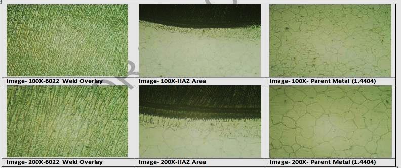
The formation of microstructure is primarily influenced by various factors, including the alloy's composition, the temperature gradient (G), the energy at the interface, and the solidification rate (R). The critical factor determining the morphology of the microstructure during solidification is the ratio between G and R. Figures 7(a) and (b) offer a clear depictionofafinecolumnarinterdendriticmicrostructurewithintheweld cladding.Incontrast,Figures7(c)and(d)reveala relatively compact heat-affected zone (HAZ) located at the weld interface between the base metal and the weld metal. The presence of this confined and inconspicuous HAZ, alongside the development of the columnar interdendritic microstructure, canbeattributedtotheutilizationofaShieldedMetalArcWelding(SMAW)processcharacterizedbycontrolledheatinputin these experiments. Furthermore, the micrograph representing the base metal distinctly showcases the emergence of an equiaxedaustenitestructure,highlightingauniquemicrostructuralcharacteristic.
Table-5PrimarydendriticarmspacingofHastelloyweldcladdingofMO-10onSS-316LbySMAWprocess
Primary Dendritic Arm Spacing (µm)
International Research Journal of Engineering and Technology (IRJET) e-ISSN:2395-0056
-6.
Tables 5 and 6 present the average and individual values, respectively, of the primary and secondary interdendritic armspacing,measuredinmicrometers(µm).Thedifferenceinmeasurementvaluesbetweenprimaryandsecondarydendrite armspacingisobserved.Theresultsindicatethattheaveragevalueofsecondaryarmspacingiscomparativelysmaller.
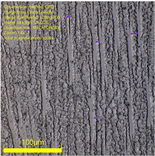
Figure 8 displays the primarydendriticarm spacing of the Hastelloy weldcladding, with a total of 4 readingstaken. Themaximumvalueofprimarydendriticarmspacingis3.826µm,whiletheminimumvalueis3.339µm.Theaverageofthese readings is 3.576 µm. In the Arc deposition process, the moderate cooling rate of the melt pool, and consequently the rapid solidificationvelocity,resultinaspacingofprimarydendriticarmsandsecondarydendriticarmspacing[33],[37],[38],[46], [48],[49],[60]–[63],asshowninFigure8.
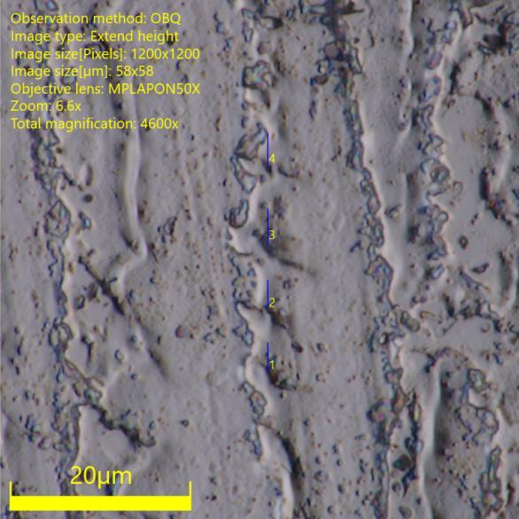
Furthermore, the solidification velocity of the melt pool facilitates the proper growth of secondary dendrites, as depictedinFigure9.TheaveragevalueofsecondarydendriticarmspacingobtainedthroughtheSMAWProcessis3.601µm. Dendrite spacings are generally correlated with mechanical strength, hardness, toughness, and corrosion resistance due to factorssuchasthedistributionofalloying elements,segregation,andsusceptibility tointergranularcorrosion. Bothprimary andsecondarydendritespacingscansignificantlyinfluencetheintegrityoftheweldcladding,assupportedbyreferences[33], [37],[38],[46],[48],[49],[60]–[63].
Volume: 11 Issue: 07 | July 2024 www.irjet.net p-ISSN:2395-0072 © 2024, IRJET | Impact Factor value: 8.226 | ISO 9001:2008 Certified Journal | Page1137
International Research Journal of Engineering and Technology (IRJET) e-ISSN:2395-0056
Volume: 11 Issue: 07 | July 2024 www.irjet.net p-ISSN:2395-0072
3.7. Corrosion Potential Test
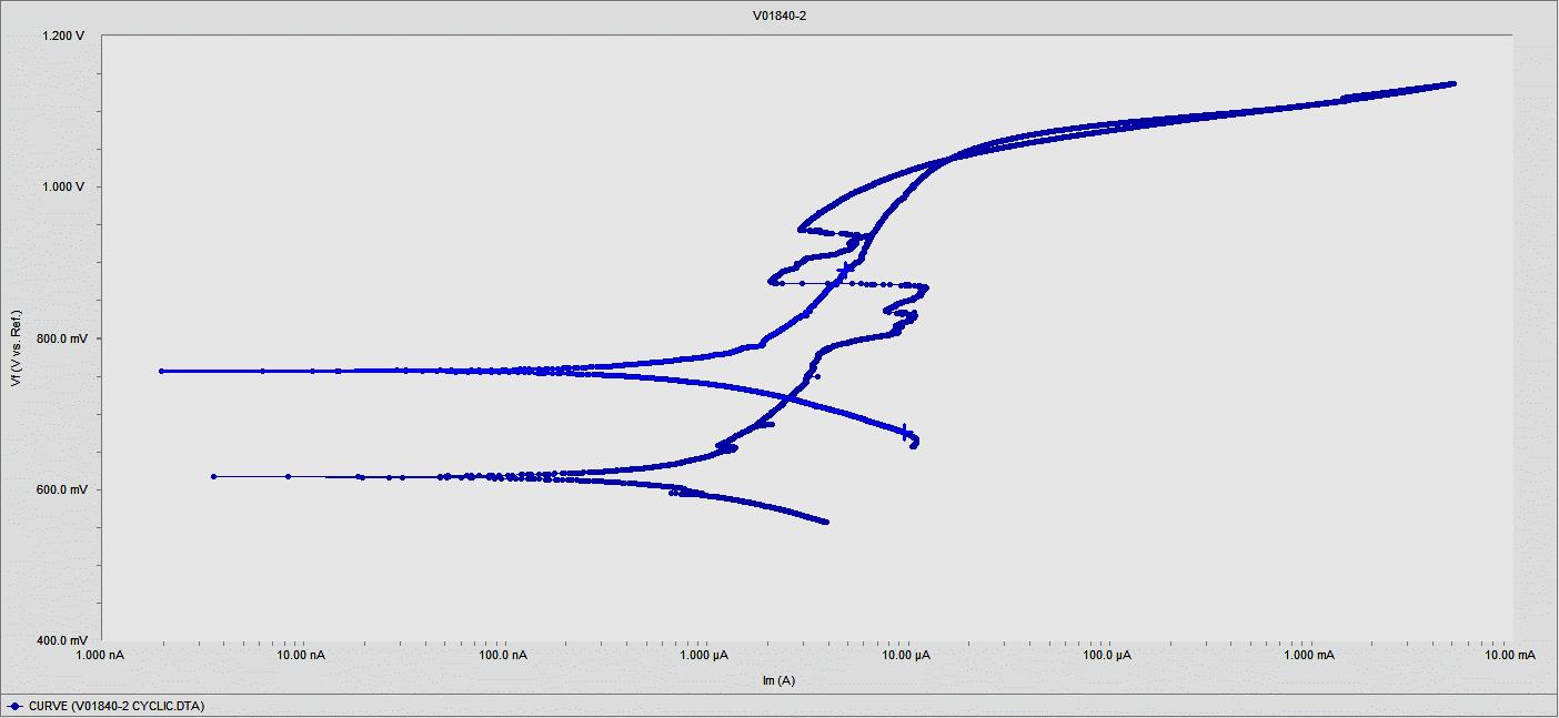
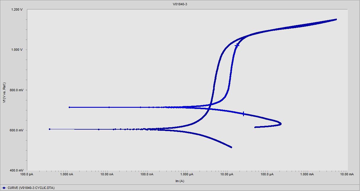
CyclicPotentiodynamicPolarizationtestswereconductedontheHastelloy MO-10weldcladdinginaFerricSulfate–50% sulfuric acid solution, following ASTM G-28, Method-A guidelines. Figures 10, 11, and 12 illustrate the potential polarizationbehavioroftheSMAWcladdingoftheHastelloy MO-10weldcladding onSS316L.Thesefiguresalsodisplaythe potentiodynamicpolarizationcurvesobtainedfromvariouslocationswithintheHastelloyMO-10weldcladding
International Research Journal of Engineering and Technology (IRJET) e-ISSN:2395-0056
PolarizationCurveofHastelloyMO-10weldcladding,Location.2
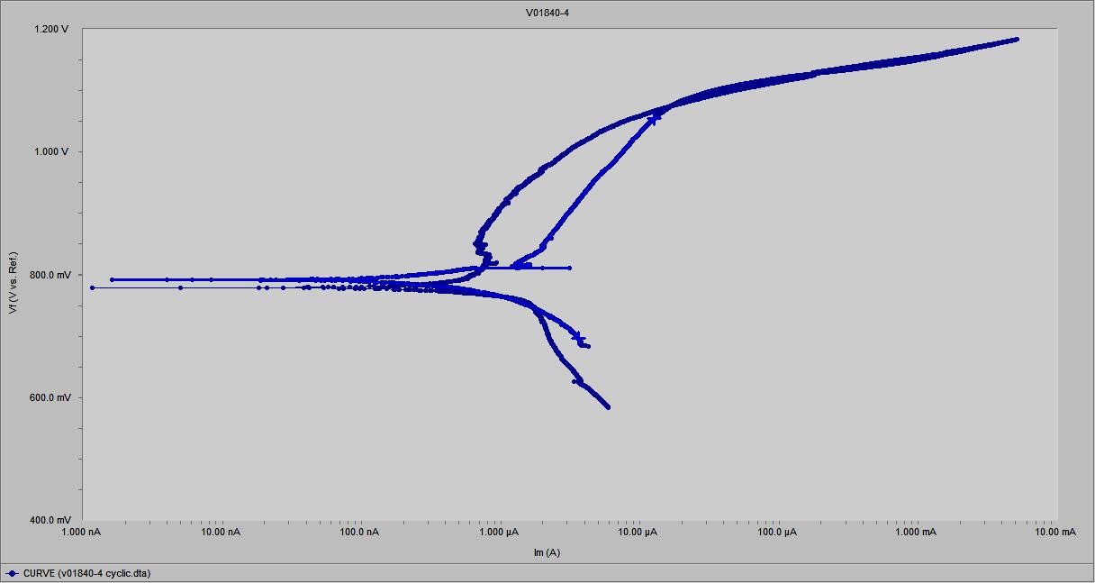
PolarizationCurveofHastelloyMO-10weldcladding,Location.3
InFigure10,11,and12,theverticalaxisrepresentsthecorrosionpotential,whilethehorizontalaxisrepresentsthe currentdensity.Thecorrosionpotential (Ecorr),corrosioncurrentdensities(Icorr), andtheanodicandcathodicTafel slopes (βaandβc)arelistedinTable8.
Volume: 11 Issue: 07 | July 2024 www.irjet.net p-ISSN:2395-0072 © 2024, IRJET | Impact Factor value: 8.226 | ISO 9001:2008 Certified Journal | Page1139
International Research Journal of Engineering and Technology (IRJET) e-ISSN:2395-0056
Volume: 11 Issue: 07 | July 2024 www.irjet.net p-ISSN:2395-0072
Parameter
Observation
Corrosion
ComparingtheresultspresentedinTable8withthecorrosionrateinmpyatvariouslocationsoftheHastelloyMO-10 Weld cladding,theaverage corrosion rate oftheHastelloy MO-10 weldcladding on SS316L achieved through SMAWis 2.20 mpy.
ThisresearchstudyaimedtoinvestigatetheutilizationofENiCrMo-10,providingvaluableinsightsintotheperformanceand characteristicsoftheweldcladding,withimplicationsforitspotentialapplicationsinthepetrochemicalindustry.Thefindings areasfollows:
TheHastelloyMo-10weldcladdingexhibitedacleansurfacewithoutweldingflaws,indicatinggoodweldability.Some issues were observed at the starting and ending points of the automated welding process, attributed to setup problemsinoperationalparameters.Overall,thesurfacequalityoftheweldcladdingwasdeemedadequate.
The Shielded Metal Arc welding process achieved adequate penetration of the Hastelloy weld cladding into the base metal,resultinginadefect-freeweldcladdingconfirmedbyMacroandVisualexamination.
Bendtestanalysisconfirmedthattheweldswerefreefromcracksorholes,demonstratingthereliabilityandoptimal parametersoftheweldingprocedure.TheintegrationbetweenthecladdinglayerandtheAISI316LSSsubstratewas foundtobesatisfactory.
Hardnessvalueswerehighestintheheat-affectedzone(HAZ),followedbytheweldcladdingandbasemetal.
ChemicalcompositionanalysisrevealedthattheweldcladdingcloselymatchedthetargetedcompositionofENiCrMo10 once a depth of 3mm from the base metal was reached. Notably, at a depth of 2.5mm from the base metal, the composition of the weld cladding closely resembled ENiCrMo-10, exceptfor the Fe content in that specific area. The regionbetween2mmand2.5mmdepthisunderscrutinyforfurtherinvestigation.Byexercisingprecisecontrolover weldingparameters,thereisapromisingopportunitytoachievethedesiredweldmetalchemistryatadepthof1mm, whichholdssignificantpotentialforrepairapplicationswithinvariousindustries.
Microstructureanalysisrevealedadefect-freeweldcladdingandanunchangedmicrostructureofthebasemetal.The SMAWprocessresultedinaheat-affectedzoneandafinecolumnarinterdendriticmicrostructure.
CorrosionpotentialtestingindicatedthattheaveragecorrosionrateoftheHastelloyMO-10weldcladdingonSS316L achievedthroughSMAWwas2.20mpy.
Overall, these findings highlight the successful utilization of Hastelloy MO-10 for weld cladding on Grade 316L using the SMAWprocess.Theresearchcontributestotheunderstandingoftheweldability,structuralintegrity,hardnesscharacteristics, and corrosion resistance of this novel material combination. The results demonstrate the suitability of the weld cladding for
International Research Journal of Engineering and Technology (IRJET) e-ISSN:2395-0056
repair and cladding applications in the petrochemical industry, pharmaceutical industry, and oil and gas industry, offering numerous benefits such as precise control, sound welds, high-quality finish, cost reduction, and streamlined production efficiency.Furtherresearchandoptimizationofweldingparameterscanenhancetheperformanceandbroadenthepotential applicationsofthismaterialcombination.
Acknowledgements:
The authors are thankful to GMM Pfaudler Ltd., Karamsad, Anand, Gujarat India, for providing machines and materials to performnecessaryexperimentalwork.
References:
[1] InternationalLabourorganization, The Future of Work in the Oil and Gas Industry,no.December.2022.
[2] C. A. Mendes Da Mota, A. Saldanha do Nascimento, D. Neves Garcia, D. A. Silva da Silva, F. Ribeiro Teixeira, and V. A. Ferraresi,“NickeloverlaydepositedbyMIGweldingandcoldwireMIGwelding,” Weld. Int.,vol.32,no.9,pp.588–598, 2018,doi:10.1080/09507116.2017.1347333.
[3] T. Materials and I. Company, “Properties and Selection: Nonferrous Alloys and Special-Purpose Materials,” Prop. Sel. NonferrousAlloy.Spec.Mater.,1990,doi:10.31399/asm.hb.v02.9781627081627.
[4] Mehta, M. V., Vora, J. J., & Chaudhari, M. D. (2021). A Review of Challenges to Hastelloy – C Series Weld Overlay. In Recent Advances in Mechanical Infrastructure (pp. 157–172). Lecture Notes in Intelligent Transportation and Infrastructure.https://doi.org/10.1007/978-981-33-4176-0_13
[5] A.ScheidandA.S.C.M.deOliveira,“AnalysisofPTAhardfacingwithCoCrWCandCoCrMoSialloys,” Soldag.Inspeção, vol.18,no.4,pp.322–328,2013,doi:10.1590/s0104-92242013000400004.
[6] E. R. Sharma, E. M. Kumar, and D. A. Kamboj, “Hastelloy C-276Weld Overlay bySMAW Process,” Int. J. Eng. Res. Appl., vol.07,no.05,pp.86–91,2017,doi:10.9790/9622-0705038691.
[7] A.Gatto,E.Bassoli,andM.Fornari,“PlasmaTransferredArcdepositionofpowderedhighperformancesalloys:Process parametersoptimisationasafunctionofalloyandgeometricalconfiguration,”Surf.CoatingsTechnol.,vol.187,no.2–3, pp.265–271,2004,doi:10.1016/j.surfcoat.2004.02.013.
[8] M.M.daSilva,V.R.Batista,T.M.Maciel,M.A.dosSantos,andT.L.Brasileiro,“Optimizationofsubmergedarcwelding process parameters for overlay welding,” Weld. Int., vol. 32, no. 2, pp. 122–129, 2018, doi: 10.1080/09507116.2017.1347325.
[9] S.R.VKumar,CLee,GVerhaeghe,“CRAWeldOverlay -InfluenceofWeldingProcessandParametersonDilutionand Corrosion Resistance,” TWI limited, 2010. https://www.twi-global.com/technical-knowledge/published-papers/craweld-overlay-influence-of-welding-process-and-parameters-on-dilution-and-corrosion-resistance#:~:text=TIG and MIGweldingprocesses,wasgenerallylessthan40%25.
[10] S.Analyticsetal.,“dissimilarescomasuperliga{basedeníquel,”2019.
[11] D. D. Deshmukh and V. D. Kalyankar, “Deposition Characteristics of Multitrack Overlayby Plasma Transferred Arc Welding on SS316Lwith Co-Cr Based Alloy-Influence ofProcess Parameters,” High Temp. Mater. Process., vol. 38, no. 2019,pp.248–263,2019,doi:10.1515/htmp-2018-0046.
[12] A. Volpi and G. Serra, “Weld Overlay of Highly Corrosion Resistant Nickel Chromium,” ASME 2018 Symp. Elev. Temp. Appl.Mater.Foss.Nucl.PetrochemicalInd.,pp.1–12,2018.
[13] R. Ranjan and A. Kumar Das, “Protection from corrosion and wear by different weld cladding techniques: A review,” Mater.TodayProc.,vol.57,pp.1687–1693,2022,doi:10.1016/j.matpr.2021.12.329.
Volume: 11 Issue: 07 | July 2024 www.irjet.net p-ISSN:2395-0072 © 2024, IRJET | Impact Factor value: 8.226 | ISO 9001:2008 Certified Journal | Page1141
International Research Journal of Engineering and Technology (IRJET) e-ISSN:2395-0056
Volume: 11 Issue: 07 | July 2024 www.irjet.net p-ISSN:2395-0072
[14] B.Khara,N.D.Mandal,A.Sarkar,M.Sarkar,B.Chakrabarti,and S.Das,“WeldCladdingwithAusteniticStainless Steel forImpartingCorrosionResistance,”IndianWeld.J.,vol.49,no.1,p.74,2016,doi:10.22486/iwj.v49i1.125902.
[15] M. Sowrirajan, P. Koshy Mathews, and S. Vijayan, “Simultaneous multi-objective optimization of stainless steel clad layer on pressure vessels using genetic algorithm,” J. Mech. Sci. Technol., vol. 32, no. 6, pp. 2559–2568, 2018, doi: 10.1007/s12206-018-0513-1.
[16] T. Kannan and J. Yoganandh, “Effect of process parameters on clad bead geometry and its shape relationships of stainlesssteelcladdingsdepositedbyGMAW,”Int.J.Adv.Manuf.Technol.,vol.47,no.9–12,pp.1083–1095,2010,doi: 10.1007/s00170-009-2226-1.
[17] N. M. and R.S. and Parmar, “Effects of welding process parameters on the geometry and dilution of the bead in the automaticsurfacing,”J.Mater.Process.Technol.,vol.41,pp.244–247,2010.
[18] P.K.PalaniandN.Murugan,“OptimizationofweldbeadgeometryforstainlesssteelcladdingsdepositedbyFCAW,” J. Mater.Process.Technol.,vol.190,no.1–3,pp.291–299,2007,doi:10.1016/j.jmatprotec.2007.02.035.
[19] J. L. Caron and J. W. Sowards, Weldability of Nickel-Base Alloys, vol. 6, no. October. 2014. doi: 10.1016/B978-0-08096532-1.00615-4.
[20] C. M. Lin, T. L. Su, and K. Y. Wu, “Effects of parameter optimization on microstructure and properties of GTAW clad weldingonAISI304LstainlesssteelusingInconel52M,” Int.J.Adv.Manuf.Technol.,vol.79,no.9–12,pp.2057–2066, 2015,doi:10.1007/s00170-015-6875-y.
[21] Haynes International Inc., “Haynes International, Physical properties of C-22,” Haynes International https://www.haynesintl.com/alloys/alloy-portfolio_/Corrosion-resistant-Alloys/HASTELLOY-C-22/physicalproperties(accessedJun.01,2020).
[22] Haynes International, “Fabrication of Hastelloy ®,” H-2010f, 2003. http://specialmetals.ir/images/technical_info/Total/hastelloys.pdf(accessedJun.01,2020).
[23] HaynesInternationalInc.,“HASTELLOY®C-2000®alloy,”H-2118A,2017.
[24] A.S.M.InternationalandA.Rights, ASMspecialtyhandbook:nickel,cobalt,andtheiralloys,vol.38,no.11.2001.doi: 10.5860/choice.38-6206.
[25] T. A. M. Haemers, D. G. Rickerby, F. Lanza, F. Geiger, and E. J. Mittemeijer, “Laser cladding of stainless steel with Hastelloy,” Adv. Eng. Mater., vol. 3, no. 4, pp. 242–245, 2001, doi: 10.1002/1527-2648(200104)3:4<242::AIDADEM242>3.0.CO;2-D.
[26] S.Zhou,G.Ma,W.Dongjiang,D.Chai,andM.Lei,“Ultrasonicvibrationassistedlaserweldingofnickel-basedalloyand Austenitestainlesssteel,”J.Manuf.Process.,vol.31,pp.759–767,2018,doi:10.1016/j.jmapro.2017.12.023.
[27] V. Advaith, A. Vaisikan, S. Thirumalini, R. Padmanaban, M. Arivarasu, and T. Ram Prabhu, “Comparative studies on pulsedGTAWandAGTAWondissimilaralloyC-22andAISI316Lweldments,”Mater.TodayProc.,vol.27,no.xxxx,pp. 2886–2895,2019,doi:10.1016/j.matpr.2020.01.613.
[28] H.-2019A Hayens International, “HASTELLOY ® C-22 ® alloy,” Hast. Int., vol. H-2019A, 2020, [Online]. Available: http://haynesintl.com/docs/default-source/pdfs/new-alloy-brochures/corrosion-resistant-alloys/brochures/c-22brochure.pdf?sfvrsn=fd7929d4_22
[29] M. V. Mehta, J. J. Vora, and M. D. Chaudhari, “A Review of Challenges to Hastelloy – C Series Weld Overlay,” 2021, pp. 157–172.doi:10.1007/978-981-33-4176-0_13.
International Research Journal of Engineering and Technology (IRJET) e-ISSN:2395-0056
Volume: 11 Issue: 07 | July 2024 www.irjet.net p-ISSN:2395-0072
[30] N. Di, “Guidelines for the welded fabrication of nickel alloys for the welded fabrication of nickel alloys for corrosionresistantservice,”NickelDev.Inst.,no.SeriesNo11012,1994,pp.29–43,1994.
[31] G.Requirements,R.Documents,andC.Composition,“SpecificationforChromiumandChromium-NickelStainlessSteel Plate,Sheet,andStripforPressureVesselsandfor,”2007.
[32] A.O.Brien,WeldingHandbook,vol.1.1969.doi:10.1007/978-1-349-00324-2.
[33] B. H. Yoon, Y. S. Ahn, and C. H. Lee, “The effect of dilution on HAZ liquation cracking in PTAW Ni-base superalloys overlaydeposit,”ISIJInt.,vol.42,no.2,pp.178–183,2002,doi:10.2355/isijinternational.42.178.
[34] S. Neyka, M. Kusch, and P. Mayr, “Progress in high performance hardfacing processes tandem-gas-metal-arc- welding andplasma-MIGhybridwelding,”ASMProc.Int.Conf.TrendsWeld.Res.,no.February2018,pp.784–790,2013.
[35] Y. Guo, D. Wu, G. Ma, and D. Guo, “Trailing heat sink effects on residual stress and distortion of pulsed laser welded Hastelloy C-276 thin sheets,” J. Mater. Process. Technol., vol. 214, no. 12, pp. 2891–2899, 2014, doi: 10.1016/j.jmatprotec.2014.06.012.
[36] J.Santander,L.Fonseca,S.Udina,andS.Marco,“AcceptedMusp,”2007,doi:10.1016/j.snb.2007.07.003.
[37] A. S. C. M. D’Oliveira, R. Vilar, and C. G. Feder, “High temperature behaviour of plasma transferred arc and laser Cobasedalloycoatings,”Appl.Surf.Sci.,vol.201,no.1–4,pp.154–160,2002,doi:10.1016/S0169-4332(02)00621-9.
[38] H. Deng, H. Shi, and S. Tsuruoka, “Influence of coating thickness and temperature on mechanical properties of steel depositedwithCo-basedalloyhardfacingcoating,” Surf.CoatingsTechnol.,vol.204,no.23,pp.3927–3934,2010,doi: 10.1016/j.surfcoat.2010.05.013.
[39] V. Balasubramanian, R. Varahamoorthy, C. S. Ramachandran, and C. Muralidharan, “Selection of welding process for hardfacingoncarbonsteelsbasedonquantitativeandqualitativefactors,”Int.J.Adv.Manuf.Technol.,vol.40,no.9–10, pp.887–897,2009,doi:10.1007/s00170-008-1406-8.
[40] C.Sudha,P.Shankar,R.V.S.Rao,R.Thirumurugesan,M.Vijayalakshmi,andB.Raj,“Microchemicalandmicrostructural studiesinaPTAweldoverlayofNi-Cr-Si-BalloyonAISI304Lstainlesssteel,”Surf.CoatingsTechnol.,vol.202,no.10, pp.2103–2112,2008,doi:10.1016/j.surfcoat.2007.08.063.
[41] S. Mandal, S. Kumar, P. Bhargava, C. H. Premsingh, C. P. Paul, and L. M. Kukreja, “An experimental investigation and analysis of PTAW process,” Mater. Manuf. Process., vol. 30, no. 9, pp. 1131–1137, 2015, doi: 10.1080/10426914.2014.984227.
[42] V. Balasubramanian, A. K. Lakshminarayanan, R. Varahamoorthy, and S. Babu, “Application of Response Surface MethodolodytoPredictionofDilutioninPlasmaTransferredArcHardfacingofStainlessSteelonCarbonSteel,”J.Iron SteelRes.Int.,vol.16,no.1,pp.44–53,2009,doi:10.1016/S1006-706X(09)60009-1.
[43] R.R.Bharath,R.Ramanathan,B.Sundararajan,andP.B.Srinivasan,“Optimizationofprocessparametersfordeposition of Stellite on X45CrSi93 steel by plasma transferred arc technique,” Mater. Des., vol. 29, no. 9, pp. 1725–1731, 2008, doi:10.1016/j.matdes.2008.03.020.
[44] S.Buytoz,A.Orhan,A.K.Gur,andU.Caligulu,“MicrostructuralDevelopmentofFe-Cr-CandB4CPowderAlloyCoating onStainlessSteelbyPlasma-TransferredArcWeldSurfacing,”Arab.J.Sci.Eng.,vol.38,no.8,pp.2197–2204,2013,doi: 10.1007/s13369-013-0599-9.
[45] F. Fernandes, B. Lopes, A. Cavaleiro, A. Ramalho, and A. Loureiro, “Effect of arc current on microstructure and wear characteristicsofa Ni-basedcoatingdepositedbyPTAongraycastiron,” Surf.CoatingsTechnol.,vol.205,no.16,pp. 4094–4106,2011,doi:10.1016/j.surfcoat.2011.03.008.
2024, IRJET | Impact Factor value: 8.226 | ISO 9001:2008 Certified Journal | Page1143
International Research Journal of Engineering and Technology (IRJET) e-ISSN:2395-0056
Volume: 11 Issue: 07 | July 2024 www.irjet.net p-ISSN:2395-0072
[46] B. C. Oberländer and E. Lugscheider, “Comparison of properties of coatings produced by laser cladding and conventional methods,” Mater. Sci. Technol. (United Kingdom), vol. 8, no. 8, pp. 657–665, 1992, doi: 10.1179/mst.1992.8.8.657.
[47] Q. Y. Wang, Y. F. Zhang, S. L. Bai, and Z. De Liu, “Microstructures, mechanical properties and corrosion resistance of Hastelloy C22 coating produced by laser cladding,” J. Alloys Compd., vol. 553, pp. 253–258, 2013, doi: 10.1016/j.jallcom.2012.10.193.
[48] Q. Y. Wang, S. L. Bai, and Z. De Liu, “Corrosion behavior of Hastelloy C22 coating produced by laser cladding in static andcavitationacidsolution,” Trans.Nonferrous Met.Soc.China(English Ed.,vol.24,no. 5,pp.1610–1618,2014,doi: 10.1016/S1003-6326(14)63232-5.
[49] P.J.E.MonsonandW.M.Steen,“Comparisonoflaserhardfacingwithconventionalprocesses,” Surf.Eng.,vol.6,no.3, pp.185–193,1990,doi:10.1179/sur.1990.6.3.185.
[50] P.Balu,P.Leggett,S.Hamid,andR.Kovacevic,“Multi-responseoptimizationoflaser-basedpowderdepositionofmultitrack single layer hastelloy C-276,” Mater. Manuf. Process., vol. 28, no. 2, pp. 173–182, 2013, doi: 10.1080/10426914.2012.677908.
[51] E. Toyserkani, A. Khajepour, and S. Corbin, “Laser Cladding Laser Cladding,” New York, vol. 11, no. 2, p. 221, 2017, [Online].Available:https://www.taylorfrancis.com/books/9781420039177
[52] Q. Y. Wang, S. L. Bai, and Z. De Liu, “Corrosion behavior of Hastelloy C22 coating produced by laser cladding in static andcavitationacidsolution,” Trans.Nonferrous Met.Soc.China(English Ed.,vol.24,no.5,pp.1610–1618,2014,doi: 10.1016/S1003-6326(14)63232-5.
[53] C. P. Alvarães, F. C. A. Madalena, L. F. G. De Souza, J. C. F. Jorge, L. S. Araújo, and M. C. Mendes, “Performance of the INCONEL 625 alloy weld overlay obtained by FCAW process,” Rev. Mater., vol. 24, no. 1, 2019, doi: 10.1590/s1517707620190001.0627.
[54] A. Tahaei, F. G. Vazquez, M. Merlin, A. Arizmendi-Morquecho, F. A. R. Valdes, and G. L. Garagnani, “Metallurgical CharacterizationofaWeldBeadCoatingAppliedbythePTAProcessontheD2ToolSteel,”Soldag.Inspeção,vol.21,no. 2,pp.209–219,2016,doi:10.1590/0104-9224/si2102.10.
[55] T. J. Antoszczyszyn, R. M. G. Paes, A. S. C. M. de Oliveira, and A. Scheid, “Impact of dilution on the microstructure and propertiesofNi-based625alloycoatings,”Soldag.Inspeção,vol.19,no.2,pp.134–144,Jun.2014,doi:10.1590/01049224/SI1902.05.
[56] E.M.Min|,Y.C.da Silva,J.Dille,andC.CarvalhoSilva,“EffectofdilutiononthemicrostructureofAWSERNiCrMo-14 alloy in overlay welding by the TIG process with cold wire feed,” Weld. Int., vol. 32, no. 2, pp. 130–138, 2018, doi: 10.1080/09507116.2017.1347326.
[57] S.L.Correia, “21o CBECIMAT - Congresso Brasileiro de Engenharia e Ciência dos Materiais 09 a 13 de Novembro de 2014,Cuiab|,MT,Brasil,”Investig.Mech.Prop.Magnes.Met.matrixCompos.withafineDispers.CeO2Part.,vol.5738, no.1,pp.2665–2672,2014,doi:10.2466/pr0.1981.48.1.335.
[58] M.Ahmad,J.I.Akhter,M.Akhtar,M.Iqbal,E.Ahmed,andM.A.Choudhry,“Microstructureandhardnessstudiesofthe electron beam welded zone of Hastelloy C-276,” J. Alloys Compd., vol. 390, no. 1–2, pp. 88–93, 2005, doi: 10.1016/j.jallcom.2004.08.031.
[59] G.Xu,M.Kutsuna,Z.Liu,andH.Zhang,“CharacteristicsofNi-basedcoatinglayerformedbylaserandplasmacladding processes,”Mater.Sci.Eng.A,vol.417,no.1–2,pp.63–72,2006,doi:10.1016/j.msea.2005.08.192.
International Research Journal of Engineering and Technology (IRJET) e-ISSN:2395-0056
Volume: 11 Issue: 07 | July 2024 www.irjet.net p-ISSN:2395-0072
[60] T. J. Antoszczyszyn, R. M. G. Paes, A. S. C. M. de Oliveira, and A. Scheid, “Impact of dilution on the microstructure and properties of Ni-based 625 alloy coatings,” Soldag. Inspeção, vol. 19, no. 2, pp. 134–144, 2014, doi: 10.1590/01049224/si1902.05.
[61] P. Varghese, E. Vetrivendan, M. K. Dash, S. Ningshen, M. Kamaraj, and U. Kamachi Mudali, “Weld overlay coating of Inconel617 Montype316 Lstainlesssteelbycoldmetaltransferprocess,” Surf.CoatingsTechnol.,vol.357,pp.1004–1013,2019,doi:10.1016/j.surfcoat.2018.10.073.
[62] A.E.Yaedu,A.S.C.M.D.Oliveira,A.E.Yaedu,andA.S.C.M.D.Oliveira,“CobaltbasedalloyPTAhardfacingondifferent substrate steels Cobalt based alloy PTA hardfacing on different substrate steels,” vol. 0836, no. March, 2016, doi: 10.1179/174328413X13789824293380.
[63] É.M.Min|,Y.C.daSilva,J.Dille,andC.C.Silva,“TheEffectofDilutiononMicrosegregationinAWSERNiCrMo-14Alloy Welding Claddings,” Metall. Mater. Trans. A Phys. Metall. Mater. Sci., vol. 47, no. 12, pp. 6138–6147, 2016, doi: 10.1007/s11661-016-3786-y.
[64] Shravan C, Radhika N, Deepak Kumar N. H., & Sivasailam B. (2023). A review on welding techniques: properties, characterisations and engineering applications. Review Article. Published online: March 5, 2023. https://doi.org/10.1080/2374068X.2023.2186638
[65] Joshi, A., Parkash, S., & Kumar, M. (2018). Study of Mechanical Properties, Microstructure and Corrosion Behavior of Super Duplex-2594 Weld Overlay on Carbon Steel Substrate by Smaw. Journal of Engineering Research and Application,8(7Part-I),65-70.ISSN:2248-9622.DOI:10.9790/9622-0807016570
[66] Kumar, V., Chandrasekhar, N., Albert, S. K., & Jayapandian, J. (2016). Analysis of arc welding process using Digital StorageOscilloscope.Measurement,81,1-12.https://doi.org/10.1016/j.measurement.2015.11.031
[67] Sim, B.-M., Tang, S.-H., Alrifaey, M., & Jong, E.-N. T. (2022). Analyzing the Effects of Heat Treatment on SMAW Duplex StainlessSteelWeldOverlays.Materials,15(5),1833.https://doi.org/10.3390/ma15051833