
International Research Journal of Engineering and Technology (IRJET) e-ISSN: 2395-0056
Volume: 11 Issue: 07 | July 2024 www.irjet.net p-ISSN: 2395-0072

International Research Journal of Engineering and Technology (IRJET) e-ISSN: 2395-0056
Volume: 11 Issue: 07 | July 2024 www.irjet.net p-ISSN: 2395-0072
Dr. Fayyaz Rehman1 , Robert Benham2
1Associate Professor, Department of Science and Engineering, Solent University, Southampton, UK
2Senior Lecturer, Department of Science and Engineering, Solent University, Southampton, UK
Abstract – AdditiveManufacturing(AM)isemergingasa cost-effective alternative to conventional manufacturing techniques for applications requiring components with complex geometries. Cost savings are achieved through reduced raw material usage, shorter manufacturing times, and the elimination of expensive tooling. AM serves as a valuable tool for designing and developing complex shapes in fluid flow research. This study examines the limitations of existing components in a 2.5 m open channel fluid flow experiment, characterized by their basic standard shapes. Specifically, it focuses on enhancing flow control in hydraulic systems by introducing gates with intricate geometries, which are typically expensive and timeconsuming to acquire from equipment suppliers. AM technology provides a cost-effective solution for implementing progressive design modifications. This paper presents a comparative analysis of various positions of an AM-produced curved drum gate in terms of flow rate, fluid velocity profile, water level height, and related fluid flow parameters. Computational Fluid Dynamics (CFD) modelling, analysis, and simulation techniques are used to analyse and validate the results. Based on the experimental findings and their verification, this paper discusses the suitability and applicability of AM techniques in fluid flow analysis.Theabilitytomanufacturecustomizedcomponents through AM offers a promising avenue for enhancing fluid flow research, enabling cost-effective and time-efficient design modifications. This study emphasizes the importance of utilizing AM and specific materials to advance fluid flow analysis.
Key Words: CFD Analysis, Additive Manufacturing, ExperimentalMethods
Additive Manufacturing (AM) is a relatively modern and innovative technology for designing and producing polymeric and metallic components, offering advantages over traditional manufacturing methods such as machining, casting, or moulding. AM enables the creation of innovative designs concerning material, shape, and complexity by eliminating the need for tooling. This removes many current design-for-manufacturing and assembly restrictions. However, AM processes have unique characteristics and requirements that must be considered during the design stage to ensure the
manufactured parts meet quality standards. AM printed parts providing distinct advantages over conventionally machined components, including reduced production time, lower costs, and the ability to achieve complex geometries. Historically, improvements in weir designs haverequiredextensiveempiricaltesting.
AdditiveManufacturing(AM)hasemergedasa promising technology for conducting fluid mechanics experiments, offering numerous possibilities. Gated spillways have attracted significant interest due to their control capabilities and reduced footprint. However, crest gates face challenges such as gate failure, support member buckling, and friction-related issues. Alternatively, radial or Tainter gates have been historically used, though they present downstream complications from high-velocity movement, cavitation probability, and aeration. Mousavimehretal.[1]investigatedshockwaveeffectsand proposed experimental methods to mitigate them, recognizing AM's potential in fluid flow research. Musa et al. [2] reviewed AM's established role in experimental fluid flow research, highlighting its significance and potentialadvancementsinvariousareas.
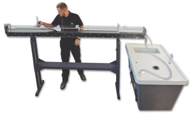
The existing experiment at the university for undergraduate Mechanical Engineering students uses a 2.5 m long flow channel (Figure 1), enabling various experimentstoobserveopenchannelflowbehaviourwith different components. This experiment currently involves only a standard round aluminium-based drum gate component.However,thisstandardroundconfigurationis insufficient to fully understand the complexities of practicaldrumgateusewithdifferentshapes.
Thecasestudypresentedinthispaperextendspreviously published research [3] by the authors, providing detailed experimental and computational fluid dynamics (CFD) analysisoftheeffectsofchangingthedrumgateshapefor various open channel experiments using additive manufacturingtechnology.
International Research Journal of Engineering and Technology (IRJET) e-ISSN: 2395-0056
Volume: 11 Issue: 07 | July 2024 www.irjet.net p-ISSN: 2395-0072
In this study/research, the poor discharge profile downstreamoftheexistingstandarddrumgate(Figure2) used as a roller gate within a flow channel is investigated (Figure3).
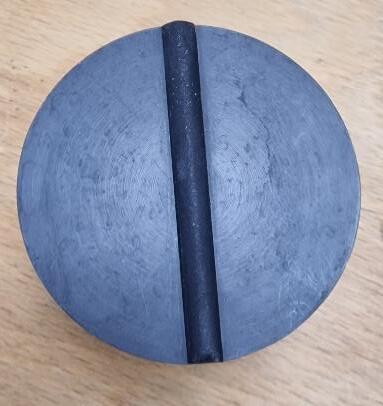
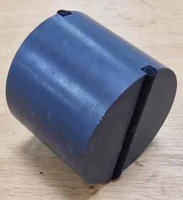
Figure2.StandardRoundDrumGate
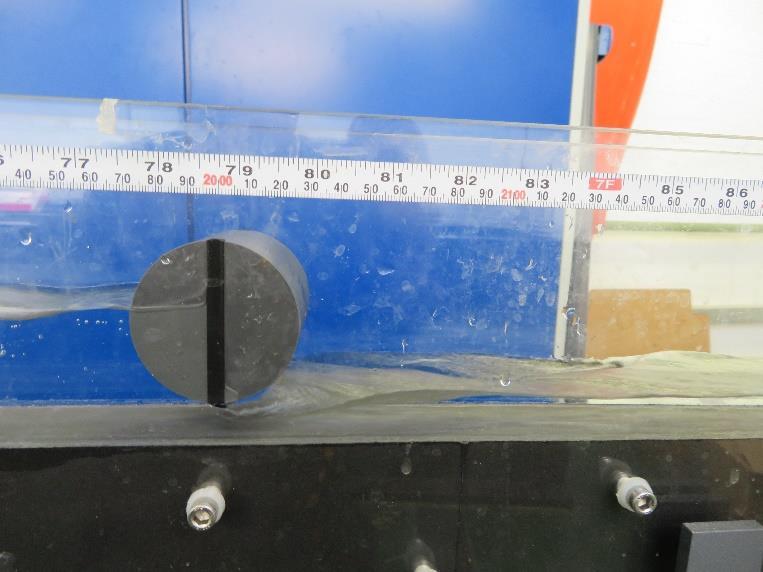
Figure3.StandardDrumGateOpenFlowExperiment
Previous roller gates with rudimentary sector designs have proven ineffective. Therefore, this research aims to enhanceroller gate design byincorporatingmathematical
curve profiles. Specifically, the study explores the utilization of a logarithmic curve profile based on the Golden ratio (ϕ), a phenomenon widely observed in nature and man-made structures [4]. This approach combines biomimicry principles with engineering disciplines. Extensive literature by Passino et al. [5] has reviewedtheadvantagesandscopeofutilizingbiomimicry in engineering. Figure 4 depicts the Golden spiral, generated through mathematical software. The polar equation (1) and its components (2) and (3) are used to plotthecurve:
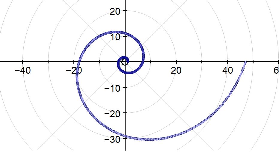
Figure4.TheGoldenspiralwasproducedusing mathematicalsoftware.
Figure 5 shows the drum profiles, featuring a logarithmic curve on one side and a standard drum on the other. For physical integration,thevariable"a" wasassigneda value of 1, and the Computer Aided Design (CAD) model was scaledtofitthedimensionsoftheexistingdrumenclosure. Data points were imported into CAD software and extruded to generate an STL file for producing an AMbaseddrumgatedesign(Figure6)
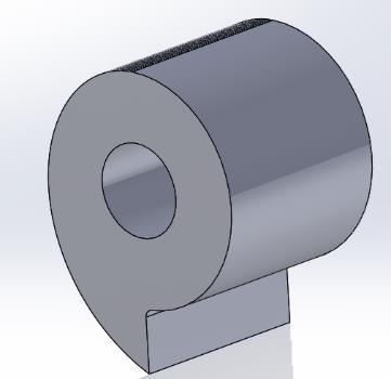

Figure5.GoldenSpiralDrumGateDesign
Volume: 11 Issue: 07 | July 2024 www.irjet.net p-ISSN: 2395-0072
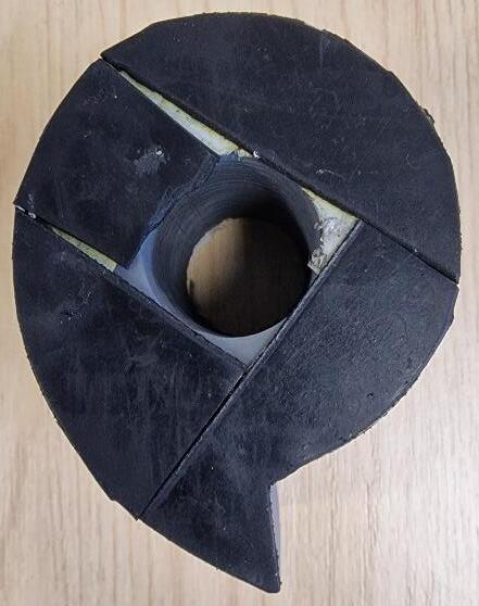
Figure6 AMBasedGoldenSpiralDrumGateDesign
The provided standard drum was tested using the AM model to enablea comparativeanalysis.To minimizeside wall leakage, the AM model was equipped with rubber mounts and sealant paper. Experimental investigations were conducted by introducing a 15 mm displacement betweenthechannelbedandthegate'slowestpoint.This displacement ensured testing across a wide range of flow rates while maintaining a sufficient water height to interact with the gate without causing overflow. Although various displacements were feasible, the initial readings focusedonexaminingthecompletespectrumofflowrates.
For a comprehensive evaluation, the newly designed AM drum gate model with a golden spiral was tested in multiplepositions,includinguprightandtilted45degrees totheleftandrightofthecentreline(Figure7).
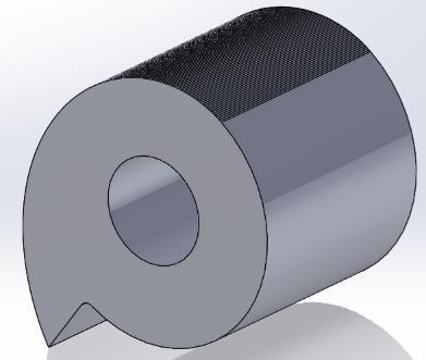
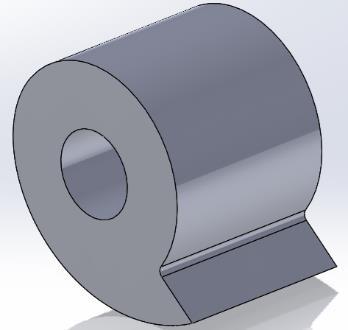
Figure7 Uprighttiltedat45degreestoleftandrightof centreline.
It was crucial to assess both upstream sides of the AM model. Therefore, after testing the rounded side (righthandsideofFigure5),the model wasreversedtotestthe logarithmic curved side (left-hand side of Figure 5). This included testing in both the upright reverse position and tilted 45 degrees to the left and right of the centreline (Figure8).

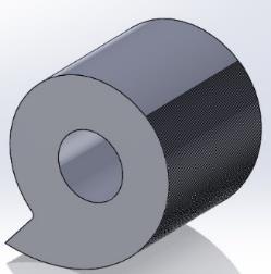
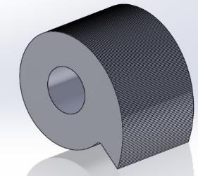
Figure8 Uprightreversedandtiltedat45degreestoleft andrightofcentreline.
The experimental setup of upright and tilted right is showninfigure9andreverseconfigurationsinfigure10.
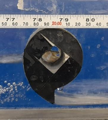
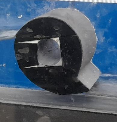
Figure9 Uprighttiltedat45degreestorightofcentreline experimentalsetupinflowchannel

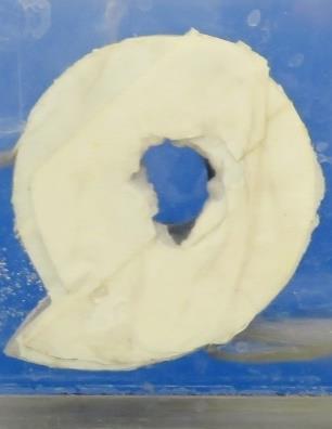
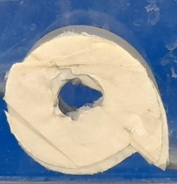
Figure10.Uprightreversedconfigurationsof experimentalsetupinflowchannel
Volume: 11 Issue: 07 | July 2024 www.irjet.net p-ISSN: 2395-0072
The results were comprehensively analysed using a spreadsheet, supplemented by observations, as findings were not immediately apparent from the spreadsheet alone.Significantvariationsinwaterheightwereobserved upstream, with the largest disparities attributed to the occurrence of a hydraulic jump, particularly pronounced at lower flow rates. Notably, when comparing the curved drum to the standard drum, the height difference caused bythehydraulicjumpwaslesspronouncedforthecurved drum. Additionally, the hydraulic jump position occurred muchfartherdownstreamwiththecurveddrum,although it shifted closer as the flow rate increased. The hydraulic jump can be concerning due to the increased hydrostatic pressureitexertsontheupstreamgate, butitcanalsobe advantageous downstream by reducing erosion rates. Visual observations indicated that fluctuations with the standarddrumweresubstantiallygreaterthanthosewith thecurveddruminbothorientations.
The analysis of Froude numbers downstream revealed relatively low values across most cases (0.59 to 2.57), which was expected given the limited flow rate of the experimentalsetup.However,thisservesasalimitationof the research, necessitating further investigation with larger channels and higher flow rates to evaluate Froude numbers for full-scale applications. Singh et al. [6] noted that the optimal Froude number range lies between 4.5 and 9.0. Upstream, supercritical flow (Fr > 1) was only observed at the lowest flow rates, as anticipated. Lower Froude numbers can lead to various downstream issues, but since the curved drum could be opened almost fully, additional investigation is warranted. The velocity of the fluid ‘V’ and the channel size also influence Froude numbersduetohydraulicdepth‘D’.
A comparative analysis of discharges was conducted, examining the performance of the original drum and the curveddrumatdifferentflowrates.Resultsindicatedthat the original drum exhibited higher values (ranging from 1.53 to 1.55) at lower flow rates compared to other findings. Interestingly, rotating the curved drum 45 degreesto theright on itscurved sideyielded thehighest value of 2.56, whereas the highest value at full flow was 1.07. However, caution is advised as these measurements were pitot tube-based, albeit separately calibrated for accuracy.
The specific energy ‘E’ can serve as an alternative comparator, considering its dependency on fluid velocity and gravitational acceleration. It also affects the volumetric flow rate ‘Q’, where the breadth of the sluice gate ‘B’ and the displacement of the lowest point of the sluice gate from the channel bed ‘d’ come into play. However,thisrelationshipisnotlinearduetothevariable coefficient of discharge ‘C’ with flow rate. To compare the performanceof variouspositions,analternativeapproach
involves plotting flow rates based on specific energies. Figures 11 and 12 depict the obtained results. This plotting method involves taking the root of the factor related to the specific energy term and plotting it against the volumetric flow rate, as per the overall equation. This technique allows for a comprehensive evaluation of the testedpositions.
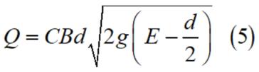
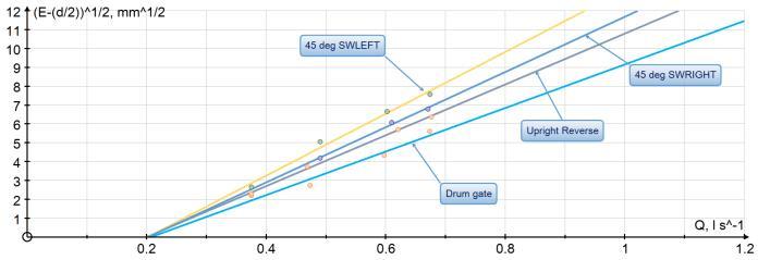
Figure11.Linearcomparisonofthestandarddrumgateto theroundedsideoftheAMmodelgate.
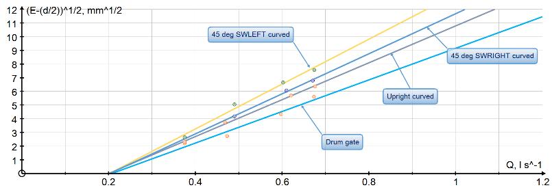
Figure12.Linearcomparisonofthestandarddrumgateto thelogarithmiccurvedsideoftheAMmodelgate.
For both orientations, the drum gate exhibits the lowest value gradient, indicating superior performance despite the absence of the coefficient of discharge. Tilting the model to the left in both orientations resulted in the highest gradient. Previous studies, such as those by Daneshfaraz et al. [7], have also focused on the impact of sluice gate geometry on performance, investigating various parameters including gate widths and different geometries.However,thecurrentresearchhaslimitations, such as the channel width. Future studies could explore other factors, including the angle of tilt of the AM model, displacement of the AM model from the channel bed, and testingdifferentsizesectors.
The paper acknowledges that certain aspects have not been thoroughly examined. For example, comparing hydrostatic pressure when the gate is closed and the stresses during different flow rates would provide valuable insights. Additionally, further investigation is warranted to study visual observations in greater detail, such as the position and sizes of hydraulic jumps and the
Volume: 11 Issue: 07 | July 2024 www.irjet.net p-ISSN: 2395-0072
oscillatory behaviour of the fluid upstream at different flowrates.
Whilethepaperfocusesontheeffectsofgeometryonflow parameters, it suggests that testing a standard drum gate with a fitted sector would be a logical step in future research. It is important to maintain focus on the most significantfindingsofthisinitialresearch,giventhebroad scope of potential testing. Furthermore, vibration problems in full-scale versions of these gates should be considered, as they can pose significant challenges. This highlightsthefindingsrelatedtosluicegategeometryand flow parameters, identifies limitations in the current research, and proposes potential avenues for further investigation. The section emphasizes the need to remain focused on the most significant outcomes of the initial study.
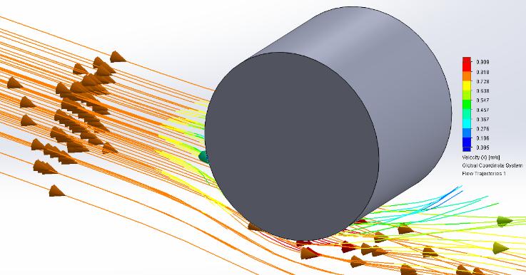
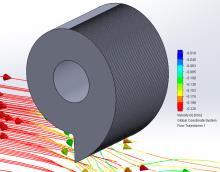
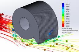
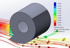
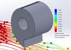
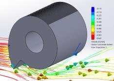
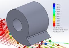
Finite Element Analysis (FEA) based Computational Fluid Dynamics (CFD) flow simulations were conducted to assess and compare the findings obtained from experimental data for four distinct types of drum gates. The flow simulations accurately predicted the fluid flow patterns and provided precise calculations of maximum velocities.TheCFDanalysisofthestandard,roundedside, and logarithmic curved side drum gates (illustrated in Figures 13, 14, and 15, respectively) demonstrated fluid flow patterns that closely matched the experimental observations.
The simulation results were also used to verify and compare the maximum velocities obtained from experimental data for standard, logarithmic side curved, and rounded drum gates (Figure 16) under full flow conditions.Although therewereslightvariationsbetween the experimental and CFD analysis velocities, the CFD velocities were slightly higher, albeit with a negligible difference.
Figure16.ComparisonofExperimental/CFDdatafor maximumvelocitiesindifferentdrumconfigurations
Inconclusion,theinitialinvestigationhasrevealedseveral intriguing findings that highlight the necessity for additional research in this field. Additive Manufacturing (AM) has played a crucial role in creating cost-effective models with intricate geometries and durable designs for drum gate applications in flow channels. Although the authorsaimtoundertakeamoreextensivetestingregime, thispreliminaryworkprimarilyconcentratedonthreekey gate positions for both orientations. The adoption of a curved gate presents several advantages, including the flexibility to accommodate various opening positions and tilt angles. The rounded side upstream of the gate has proven effective in minimizing hydraulic jumps, reducing vibrations, and improving the flow profile. Research by Yousif et al. [8] has explored and modelled the damage caused by scouring. The correctly oriented logarithmic curved side of the gate significantly enhances the flow profile. It is notable that the specific energies for the AM models are higher, which also includes greater hydraulic depths. This prompts questions about the pressures exerted on the gates at elevated flow rates. However, similar engineering design challenges have been faced by modern radial gates and other rounded gates. The fullscale implementation of a curved gate requires careful
International Research Journal of Engineering and Technology (IRJET) e-ISSN: 2395-0056
Volume: 11 Issue: 07 | July 2024 www.irjet.net p-ISSN: 2395-0072
consideration. While curved gates may not always be justifiable in contemporary spillways and reservoirs, they are valuable for measurement applications, and are particularly useful in channels and spillways where it is critical to address vibration and scouring issues immediatelyupstreamofthesluicegate.Thefindingsfrom this research have the potential to resolve some existing issuesinflowsystemsandcontributetoimprovementsin these areas. Future research should build on these initial findings to further refine our understanding and applicationofcurvedgatesinflowchannels.
[1] Mousavimehr,S.M.,Yamini,O.A.,&Kavianpour,M.R. (2021). Performance assessment of shockwaves of chute spillways in large dams. Shock and Vibration, 2021,1-17.
[2] Musa, M., Ghobrial, L., Sasthav, C., Heineman, J., Rencheck, M., & Stewart, K. (2023). Advanced Manufacturing and Materials for Hydropower: ChallengesandOpportunities.
[3] Benham, R., Rehman, F. & Joshi, A., 24 Nov 2023, Advances in Manufacturing Technology XXXVI: Proceedings of the 20th International Conference on Manufacturing Research, Incorporating the 37th NationalConferenceonManufacturingResearch,6th–8th September 2023, Aberystwyth University, UK. Thomas, A., Murphy, L., Morris, W., Dispenza, V. & Jones, D. (eds.). IOS Press, p. 53-58 6 p. (Advances in TransdisciplinaryEngineering).
[4] Passino, K. M. (2005). Biomimicry for optimization, control, and automation. Springer Science & Business Media.
[5] Maor,E.(2009)."e":TheStoryofaNumber(Vol.41). PrincetonUniversityPress.
[6] Singh,D.,Paswan,A.P.,Anbukumar,S.,&Meena,R.K. (2022). Experimental Simulation of Hydraulic Jump for the Study of Sequent Depth Using an Obstruction. InHydraulicandCivilEngineeringTechnologyVII(pp. 3-14).IOSPress.
[7] Daneshfaraz, R., Norouzi, R., Ebadzadeh, P., Di Francesco, S., & Abraham, J. P. (2023). Experimental Study of Geometric Shape and Size of Sill Effects on the Hydraulic Performance of Sluice Gates. Water, 15(2),314.
[8] Yousif, A. A., Sulaiman, S. O., Diop, L., Ehteram, M., Shahid, S., Al-Ansari, N., & Yaseen, Z. M. (2019). Open channel sluice gate scouring parameters prediction: different scenarios of dimensional and nondimensionalinputparameters.Water,11(2),353.


“Dr. Fayyaz Rehman is an Associate Professor at Department of Science and Engineering, Solent University, UK.HeisaFellowofHigherEducation Academy, a Chartered Engineer from the Engineering Council and a Fellow of the Institution of Engineering Designers,UK Heisalsovicechairand committee member of the Consortium of UK Manufacturing Engineering Heads (COMEH), a UK-based body responsible for promoting manufacturing engineering education andresearch,aswellasorganizingthe International Conference on Manufacturing Research (ICMR) conference series annually. His research interests are CAD/CAM/CAE, Material Testing and Additive ManufacturingTechnologies.”

“Rob Benham is a senior lecturer at Department of Science and Engineering, Solent University, UK. and currently a course leader for the HNCEngineeringandFoundationYear Engineering. He has been teaching engineering courses at Solent University for over 15 years. Prior to the introduction of individual course leaders, he was programme leader on the old engineering programme. In 2003 Rob completed his PGCE (postcompulsory education) at Oxford Brookes University. He then taught in further education for one additional year. He continued some FE teaching and supply teaching when working part-time. In addition to this, in more recent times, Rob has delivered many taster days at Solent. He has strong research interests in manufacturing and materials. As a result, he brings a wide range of experience of educational settings with a diverse scopeoflearners.”