
International Research Journal of Engineering and Technology (IRJET) e-ISSN: 2395-0056
Volume: 11 Issue: 07 | July 2024 www.irjet.net p-ISSN: 2395-0072

International Research Journal of Engineering and Technology (IRJET) e-ISSN: 2395-0056
Volume: 11 Issue: 07 | July 2024 www.irjet.net p-ISSN: 2395-0072
Girish Tukaram Panchal1 , Dr. Pravin T. Nitnaware2
1Research Scholar, D Y Patil College of Engineering, Akurdi, Pune 411044 Maharashtra, India
2HOD, Mechanical Engineering, Department of Mechanical Engineering D Y Patil College of Engineering, Akurdi, Pune 411044 Maharashtra, India ***
Abstract - Engines are widely used to convert chemical energyintomechanicalenergyforpowergeneration.Theycan be classified into Spark Ignition and Compression Ignition Engines based on the nature of combustion. In both engine types, air-fuel mixture is compressed before ignition, and the compression ratio determines the extent of compression. Highercompressionratiosgenerallyresultinincreasedpower output.
While several parameters such as fuel-air ratio, valve timing, and spark timing can be controlled to enhance engine performance, there are limited options for dynamically adjustingthecompressionratioduringengineoperation.This research aims to develop a method for modifying the compression ratio of an engine to achieve optimal performance.
The proposed approach involves connecting the piston to a primary connecting rod, which, in turn, connects to a first slider joint. The crankshaft is connected to a secondary connecting rod, which is linked to a second slider joint. Both slider joints can slide along a pivoted slider arm, enabling adjustment of the leverage around the pivot point.
By employing this variable compression ratio method, it becomespossibletoachievevariousperformanceandemission improvements in the engine. Additionally, a single engine can accommodate the combustion of different fuel types such as petrol, diesel, CNG, and hydrogen, among others.
Key Words: VariableCompressionRatio,ConstantClearance Volume,InternalCombustionEngine,LinkageMechanism, KinematicSimulation.
Engineconvertsvariousformsofenergiesintomechanical powerandenablesthemobilityandtransportation.Engines are categorized based on the parameters like type of combustion, fuels being used, etc. Achieving efficient and cleanenergyconversionhasalwaysbeenachallengewhile improvingtheperformanceofengine.Multipleparameters like spark timing, air-fuel ratio, valve timing etc., are exploredintheresearchworkdonebymanyresearchersto
improve performance and reduce emissions from engine. Compressionratioisoneofthesignificantparameterwhich greatlyinfluencestheperformanceandemissionsofSpark Ignition (SI) and Compression Ignition (CI) engines. Compression ratio describes the ratio of cylinder’s total volume when the piston is bottom-most position with the clearancevolumewhenthepistonisattop-mostposition. With the help of higher compression ratio in engine, it is possible to extract maximum energy from fuel during the combustionprocessandthermalefficiencycanbeimproved. Fuelconsumptioncanbereduced,anddesiredcombustion temperatures can be achieved with the help of optimum compressionratio.Alsoexpansioncyclescanbeextended, mechanical power output can be increased, and exhaust temperatures can be lowered by optimizing compression ratio.
GasolinefuelisusedinSIengine,anditisdescribedwiththe parameterslikeOctanenumber,whichismeasurement of fuel’s resistance to detonation or preignition inside the engine.
Higher-octanefuelsexhibitgreaterresistancetoautoignition underhighercombustionpressureandheat.Similarly,the cetane number measuresthecombustion qualityofdiesel fuel or the ignition delay. Higher cetane numbers indicate shorterignitiondelaysandbetterfuelquality.Bothgasoline and diesel fuels exhibit variations in performance and emissionsdependingonthecompressionratio.However,the conventionalconstructionofenginesimposeslimitationson achievingavariablecompressionratiosuitableforavariety offuels.Thefixedlinkageoftheconnectingrodbetweenthe piston and crankshaft using rotary joints at both ends restrictsthepiston'straveltotherotationofthecrankshaft, resultinginaconstantcompressionratio.
Overcoming the challenges posed by conventional engine construction,a fewattemptshavebeenmadetoachievea variablecompressionratio.Theseattemptsincludealtering thepistonstrokeusinghydraulicorelectricactuatorswithin the connecting rod, dynamically adjusting the piston-tocrankshaftdistance,modifyingthecylinderorpistonheight, amongothers.However,noattemptshavebeenobservedto achieve a constant clearance volume while varying the
International Research Journal of Engineering and Technology (IRJET) e-ISSN: 2395-0056
Volume: 11 Issue: 07 | July 2024 www.irjet.net
piston position to achieve the desired compression ratio withorwithoutcontinuouschangesinthedistancebetween thepistonandcrankshaft.
Thisresearchpresentsanovelmethodforachievingvariable compression ratio in engines, thereby maximizing performanceandincreasingcompatibilitywithavarietyof fuels.Proposedconstructionofmechanismincludesexisting pistonandcrankshaftconfiguration,withtheconnectingrod divided into three components which are primary connectingrod,sliderarm,andsecondaryconnectingrod. Compressionstrokeofthepistoncanbevariedbyadjusting the position of slider arm which enables the desired compressionratio.Widerangeofperformanceandemission variations can be achieved from the engine by using this methodforadjustingcompressionratio.Alsowiththehelp ofvaryingcompressionratio,asingleenginecanfacilitate the proper and efficient combustion of various fuel types such as petrol, diesel, compressed natural gas (CNG), hydrogen,etc.
2.1
p-ISSN: 2395-0072
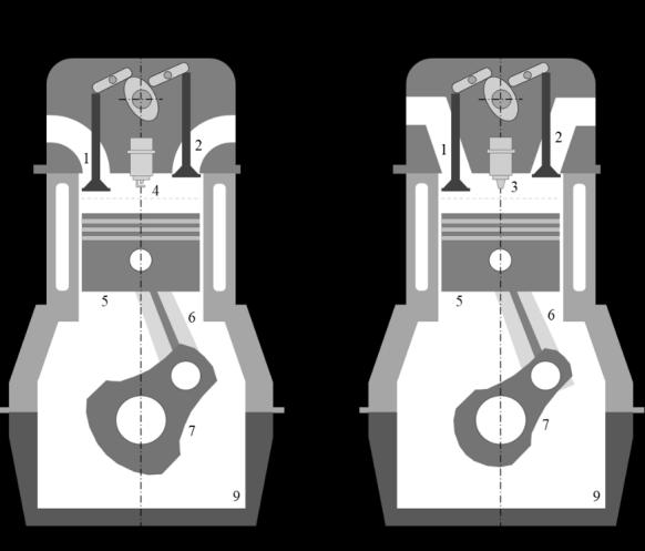
Dedicatedarrangementisprovidedbetweenthepiston andcrankshafttoachieveavariablecompressionratioinan internalcombustionengine.Thisarrangementcanselectively adjust the piston's bottom dead center position while ensuring that the clearance volume at top dead center position remains consistent across achieved compression ratios. Maintaining a constant clearance volume while changing compression ratios is necessary to meet specific combustion process parameters and to avoid issues like knocking,etc.
Sr.No. NameofComponent
1. Piston
2. PrimaryConnectingRod
3. SliderArm
4. SliderJoint1
5. SliderJoint2
6. SliderJoint3
7. VerticalGuide
8. SecondaryConnectingRod
9. Crankshaft
10 SliderPivotAssembly
11. Leadscrew
12. HandleLeverAssembly
13. Motor
14. EngineHousingframe
International Research Journal of Engineering and Technology (IRJET) e-ISSN: 2395-0056
Volume: 11 Issue: 07 | July 2024 www.irjet.net p-ISSN: 2395-0072
1. Piston:Inthisdesign,thepistonissimilartoconventional pistons,butwithananti-rotationfeatureforthepistonpin. This prevents any rotation between the piston and piston pin, creating a rigid joint with the connecting rod. Unlike conventionalconstruction,thereisnorotaryjointbetween theconnectingrodandpiston.
2. Primary Connecting Rod: Unlike conventional engine construction with a single connecting rod, this design incorporatesmultipleconnectingrods.Itfeaturesaprimary connecting rod connected to the piston and a secondary connectingrodlinkedtothecrankshaft.Thisarrangement allows the connecting rod to move in a straight line concentric to the piston/cylinder due to a rigid joint connection.
3. Slider Arm: The slider arm, connected to both the primary and secondary connecting rods through slider joints,facilitatesthetransferofmotionbetweenthepiston andcrankshaft.Withapivotendassemblyononeend,the slider arm can rotate in the plane of piston movement, enablingefficientoperation.
4. SliderJoint1:SliderJoint1incorporatesalinearbearing thatallowsittoslidealongthesliderarm.Thisjointensures theprimaryconnectingrodcanmoveverticallyinalinear manner, unaffected by the rotational motion of the slider arm.
5. SliderJoint2:SliderJoin2isalsoequippedwithlinear bearing which slides on Slider Arm and also connected to SecondaryConnectingRod.ThepurposeoftheSliderJoint2 istomaintainthelinearverticalmovementoftheSecondary Connecting Rod irrespective of the rotary motion of the SliderArm.
6. SliderJoint3:SlideJoint3isalsoequippedwithlinear bearingandslidesonVerticalGuidewhichhelpstomaintain linearverticalmovementoftheSecondaryConnectingRod.
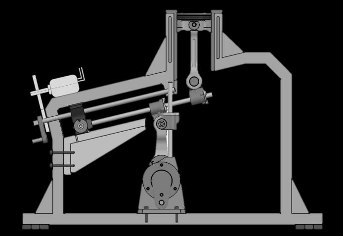
7. SliderPivotAssembly:SliderPivotAssemblyisconnected toSliderArmandabletoslidebetweenthechannelscreated inEngineHousingframe.SliderPivotAssemblyallowsSlider ArmtorotateinaplaneofPistonmovementwiththehelpof rotaryjoint.SliderPivotAssemblygotinternalthreadingand is mounted on Leadscrew which can move it forward and rearward.
8. Leadscrew: Leadscrew is a threaded pin which is mountedwithreferencetoHousingandcanmovetheSlider PivotAssemblyforwardandrearwardwiththehelpofscrew typeconnection.Leadscrewmaybeequippedwithhandle lever for manual operation or gear motor connection for electricaloperation.
9. Vertical Guide: Vertical Guide is installed in Engine HousingframeandprovideguidingdirectiontoSecondary ConnectingRodwiththehelpofSliderJoint3.
10.SecondaryConnectingRod:SecondaryConnectingRodis connected to Crankshaft as per conventional construction andalsoconnectedtoSliderJoint2and3usingrotaryjoint. Sliderjoint2transfersthemotionreceivedfromSliderarm toSecondaryConnectingRodandvice-versa.SliderJoint3 guidestheSecondaryConnectingrodalongthedirectionof VerticalGuide.
11.Crankshaft: Crankshaft is similar to conventional crankshafts except the stroke is optimized to suit the Variablecompressionratioandpackagingrequirementsof mechanism.
12.EngineHousingframe:EngineHousingframeprovides rigidframeworkforthefunctioningofwholemechanism.It includes cylinder for guiding of Piston, provides sliding arrangement for Slider Pivot Assembly, location for leadscrew,locationforverticalguideandprovidesmounting arrangementforcrankshaftlikeconventionalconstruction.
3DCADsoftwareisusingforpreparingandsimulatingthe CADmodel.ForKinematicSimulationfollowingarethesteps used
1. CreateMechanism
a. Create Joints: Joints define the type of movement expectedbetweentwoparts
i. Rigid joint connection is applied to all stationary parts
ii. Revolute joint connection is given between CrankshaftandHousing,CrankshaftandSecondary ConnectingRod,ConnectingRodandSliderJoint2, SliderPivotassemblyandSliderArm,SliderJoint1 andPrimaryConnectingRod,LeadscrewandEngine Housing.
iii. CylindricaljointconnectionisgivenbetweenSlider Joint2andSliderArm,SliderJoint1andSliderArm, Piston and Engine Housing, Slide Joint 3 and Vertical Guide, Slider Joint 3 and Secondary Connecting Rod, Leadscrew and Slider Pivot Assembly.
b. Provide Commands: It defines the amount of movementexpectedinJoints
i. Command1isgivenforCrankshaftrotationtoallow itrotatein360deg
International Research Journal of Engineering and Technology (IRJET) e-ISSN: 2395-0056
Volume: 11 Issue: 07 | July 2024 www.irjet.net p-ISSN: 2395-0072
ii. Command2isgivenforlinearmovementofSlider Pivot Assembly with respect to Leadscrew. It is specified from -100 to 100mm and 0 is the initial position
iii. Command 3 is given between Piston Pin and Primary connecting Rod to allow it for rotational displacement. 0deg position is maintained throughoutthesimulation
iv. Command4isgiventoHandleleverassemblywhich isconnectedtoLeadscrew.Itallowsrotationofthe Handle lever and Leadscrew with respect to the EngineHousing.
After defining the Joints and Commands if Degree of Freedomis0thenonlyMechanismcanbesimulated.
2. EditSimulation
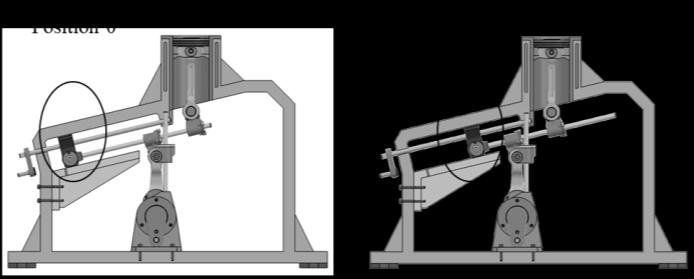
a. For Simulation 1 which is for Lower Compression Ratio, Command 1 is kept with value 0 which is initial position of Slider Pivot Assembly and then saved as Position 0 of Simulation. Then Command 1 value is modified to 360 and then it is saved as Position 1. Command2,3and4iskeptwithvalue0throughoutthe simulation which specifies the Initial position of Slider Pivot Assembly, Vertical alignment of Primary Connecting Rod and Bottom position of Handle Lever respectively.
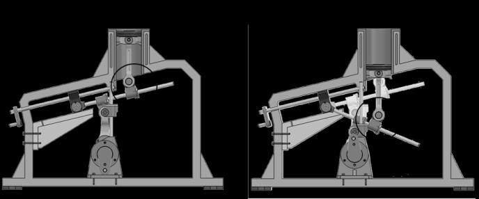
b. ForSimulation2whichisforshowingthemovement SliderPivotAssemblyusingLeadscrew.HenceCommand 2iskeptwithvalue0andCommand4iskeptwithvalue360 for showing the initial position of Slider Pivot AssemblyandinitialpositionofHandleLeverassembly. ThisissavedasPosition0ofsimulation.ThenCommand 2ismodifiedtovalue100andCommand4ismodifiedto value 360 and then saved as Position 1 of Simulation. OtherCommandslike1and3iskeptwithconstantvalue of0forshowingtheTopDeadCenterpositionofPiston andVerticalalignmentofPrimaryConnectingRod.
c. For Simulation 3 which is for Higher Compression Ratio,Command2ismodifiedwithvalue100todefine theforwardpositionofSliderPivotAssemblyandkept constant.Command1iskeptwithvalue0whichisinitial position of Slider Pivot Assembly and then saved as Position 0 of Simulation. Then Command 1 value is modified to 360 and then it is saved as Position 1. Command 3 and 4 is kept with value 0 throughout the simulation which specifies the Vertical alignment of PrimaryConnectingRodandBottompositionofHandle Leverrespectively.
Afterdefiningtheinitial andfinal stepofthesimulationit canbesimulatedtodemonstrateexpectedmovementofthe components.ForrunningthesimulationLoopmodeiskept
on continuous mode for running it continuously and Interpolation step is defined as 0.01 to achieve slow and understandableresultsofsimulation.
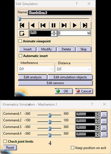
Table -3: ComponentsinFig3
Sr.No. NameofCommand Purpose Value
LoopMode Forchanging loopmode Continuous
InsertButton Forsavingthe step NA
InterpolationStep Forspeedof Simulation 0.01
SliderCursor Fordefining thestep Asper Simulation
During Simulation 1 which is prepared for demonstrating lowercompressionratio,SliderPivotAssemblyisatInitial position. Piston and Primary Connecting Rod moves up/downandprovidesrotarymotiontoSliderArmwiththe helpofSliderJoint1.SliderJoint2receivesthemotionfrom the Slider Arm and pushes the Secondary Connecting Rod whichin-turnrotatestheCrankshaft.SliderJoint3guideson VerticalGuidetoprovidelinearverticalmotiontoSecondary ConnectingRod.
International Research Journal of Engineering and Technology (IRJET) e-ISSN: 2395-0056
Volume: 11 Issue: 07 | July 2024 www.irjet.net p-ISSN: 2395-0072
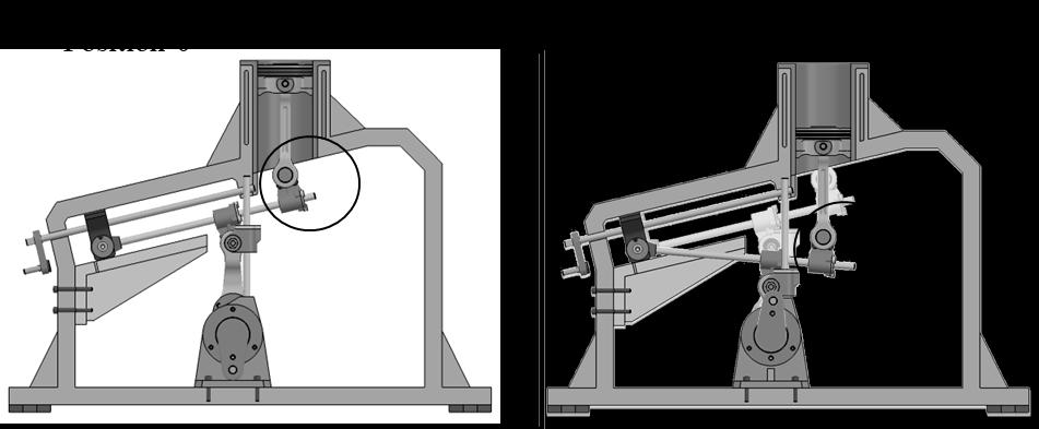
Simulation 2 is prepared to show the movement of Slider PivotAssemblyinsidetheEngineHousingusingLeadscrew andHandleleverassembly.InthisSimulationHandleLever Assembly and Leadscrew rotates with reference to the EngineHousingframeandmovestheSliderPivotAssembly forwardfrominitialpositionusingscrewjointconnection. Thisdemonstratesthemethodtoachievethedifferentpivot positions for Slider Arm so that it can provide different strokes to Secondary Connecting Rod while maintaining sametoppositionofthePiston.
During Simulation 3 which is prepared for demonstrating higher compression ratio, Slider Pivot Assembly is at forward position than initial position. Piston and Primary ConnectingRodmovesup/downandprovidesrotarymotion toSliderArm with thehelp ofSlider Joint1. Slider Joint 2 receives the motion from the Slider Arm and pushes the Secondary Connecting Rod which in-turn rotates the Crankshaft.SliderJoint3guidesonVerticalGuidetoprovide linearverticalmotiontoSecondaryConnectingRod.
FollowingdimensionsareusedtoPrepareCADmodel
PistonDiameter=77mm
PrimaryConnectingRodLength=130mm
SecondaryConnectingRodLength=100mm
CrankshaftThrow=30mm
SliderPivotAssemblyStroke=130mm
ClearanceVolumeheight=8.85mm
FollowingaretheresultsfromtheKinematicsimulation
PistonStrokeforLowerCompressionRatio=86.4mm
PistonStrokeforHigherCompressionRatio=114.1mm
AspertheformulatocalculateCompressionratio,whichis CompressionRatio=TotalVolume/ClearanceVolume
Total Volume = Clearance Volume + Piston Stroke or DisplacedVolume (1)
Let’sDenote
CompressionRatio=CR
TotalVolume=Vtl
ClearanceVolume=Vcl
DisplacedVolume=Vdl
Hence,CR=Vtl/Vcl (2)
Because,Vtl=(Vcl+Vdl)fromequation(1)
HencebyputtingvalueofVtlinequation(2)
Itgives,CR=(Vcl+Vdl)/Vcl (3)
AsperthedimensionsoftheCADmodel,
ClearanceVolume=Vcl=41490.54mm3
Displaced Volume for Lower Compression = Vdls1 = 402332.46mm3
Displaced Volume for Higher Compression = Vdls2 = 531320.99mm3
International Research Journal of Engineering and Technology (IRJET) e-ISSN: 2395-0056
Volume: 11 Issue: 07 | July 2024 www.irjet.net p-ISSN: 2395-0072
Usingtheaboveformulainequation(3)andabovevalues
LowerCompressionRatio=10.7
HigherCompressionRatio=13.8
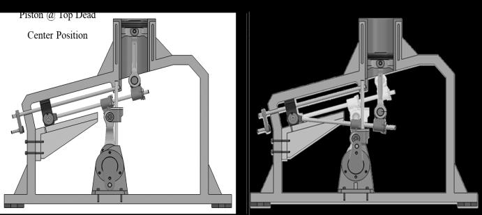
Fig -7:ResultsoftheKinematicSimulation1
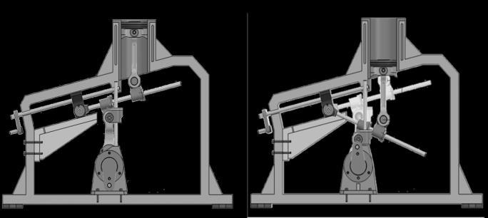
Fig -8:ResultsoftheKinematicSimulation2
Table -4: DetailsofExistingEngine
Engine
Table -5: DetailsofProposedEngine
ProposedVCREngine
AccordingtotheResultsoftheKinematicSimulationlower and higher compression ratio can be achieved using the mentionedmechanism.TataMotorsvehicleTiago’sengine specificationsareusedforcomparison.
- MinimumCompressionratiowhichcanbeachievedusing proposedVCRmechanismis10.7whichisequivalentto theTataTiagoPetrolEngine
- Maximum Compression ratio which can be achieved using proposed VCR mechanism is 13.8 which is equivalenttothestandardcompressionratioforCNGas afuelisbetween13to14.Thisaddressesthelimitation ofusingsamecompressionratioofPetrolengineforCNG fuel.
- 7 new types of parts will need to be added in the mechanism between Piston and Crankshaft to achieve VariableCompressionRatio.
- ClearanceVolumeinsideEngineCylinderispossibleto keepconstantevenaftervaryingthecompressionratio, which helps to consume the minimum amount of fuel comparedtotheotherexistingVCRmechanismsandcan improveVolumetricfuelefficiency.
However,morestudyontheVCR mechanismisnecessary whiletakingthefollowingfactorsintoaccount.
- Effects of new moving parts on the Speed and Torque requirementsfromEngine
International Research Journal of Engineering and Technology (IRJET) e-ISSN: 2395-0056
Volume: 11 Issue: 07 | July 2024 www.irjet.net p-ISSN: 2395-0072
- Effects of change in RPM of Crankshaft due to the VCR mechanismarrangement
- PerformanceandEmissionsofEngineusingPetroland CNGfuelwithVCRmechanism
- Effect of Construction and Size on mounting and balancingarrangementsofEnginewithVCRmechanism
[1] Mohammed Kadhim Allawi. (2016). The Effect of CompressionRatiouponthePerformanceandEmission of spark ignition engine. In International Journal of EngineeringandTechnicalResearch(IJETR)ISSN:23210869(O)2454-4698(P),Volume-5,Issue-3,July2016
[2] AinaT.,FolayanC.O.andPamG.Y.(2012).Influenceof compressionratioontheperformancecharacteristicsof a spark ignition engine. In Pelagia Research Library AdvancesinAppliedScienceResearch,ISSN:0976-8610 CODEN(USA):AASRFC,2012,3(4):1915-1922.
[3] RinuThomas,M.Sreesankaran,JeevanJaidi,DileepM. PaulandP.Manjunath.(2016).Experimentalevaluation oftheeffectofcompressionratioonperformanceand emission of SI engine fuelled with gasoline and nbutanol blend at different loads. In Perspectives in Science (2016) 8, 743 746, http://dx.doi.org/10.1016/j.pisc.2016.06.076
[4] Pischinger S., Wittek K. and Tiemann C. (2009). TwostageVariableCompressionRatiowithEccentricPiston Pin. In MTZ worldwide (Vol. 70, Issue 2, pp. 20–27). Springer Science and Business Media LLC. https://doi.org/10.1007/bf03227930
[5] Khan,I.R.(2017).StudyofVariableCompressionRatio Engine(VCR)andDifferentInnovationstoAchieveVCR. InInternationalJournalforResearchinAppliedScience andEngineeringTechnology:Vol.V(IssueXI,pp.1473–1478). International Journal for Research in Applied Science and Engineering Technology (IJRASET). https://doi.org/10.22214/ijraset.2017.11213
[6] FarhaTabassumAnsari,AbhishekPrakashVerma,Alok Chaube.(2013).EffectonPerformanceandEmissionsof SI Engine Using Ethanol as Blend Fuel Under Varying Compression Ratio. In International Journal of EngineeringResearch&Technology(IJERT)Vol.2Issue 12, ISSN: 2278-0181, December – 2013. DOI : 10.17577/IJERTV2IS120418
[7] AnandRamachandranandProf.A.VWaghmare.(2016). ExperimentalInvestigationoftheeffectofCompression RatioontheperformanceofadedicatedCNGengine.In International Engineering Research Journal (IERJ)
Volume 2 Issue 5 Page 1925-1929, 2016, ISSN 23951621,October–2016
[8] KrishnaPrasadSandRSaravanan.(2020).TheStudyof ImpactofCompressionRatioonthePerformance and EmissionCharacteristicsofDTSiEngineusingPetroland CNG as Fuel. In Palarch’s Journal Of Archaeology Of Egypt/Egyptology17(9).ISSN1567-214x,PJAEE,17(9) (2020)
[9] AsperthefiguresmentionedonBPIndonesiaWebpage, SpecificCompressionratioissuitableforspecificOctane number fuel. https://www.bp.com/en_id/indonesia/home/productsand-services/fuels-retail/news-article/type-of-fuelthat-is-suitable-for-your-vehicle.html


Photo
Mr.GirishTukaramPanchal M.Tech.AutomotiveEngg Research Scholar, D.Y.P.C.O.E., Akurdi,Pune-411044
Dr.PravinT.Nitnaware HODMechanicalEngineering, D.Y.P.C.O.E.,Akurdi,Pune-411044