
International Research Journal of Engineering and Technology (IRJET) e-ISSN: 2395-0056
Volume: 11 Issue: 07 | July 2024 www.irjet.net p-ISSN: 2395-0072

International Research Journal of Engineering and Technology (IRJET) e-ISSN: 2395-0056
Volume: 11 Issue: 07 | July 2024 www.irjet.net p-ISSN: 2395-0072
Shripal Tiwari1, Prof. Anubhav Rai2
1M-Tech Student, Department of Civil Engineering & Gyan Ganga Inst. Of Tech. & Sciences Jabalpur M.P. India
2Professor and H.O.D. Department of Civil Engineering & Gyan Ganga Inst. Of Tech. & Sciences Jabalpur M.P. India
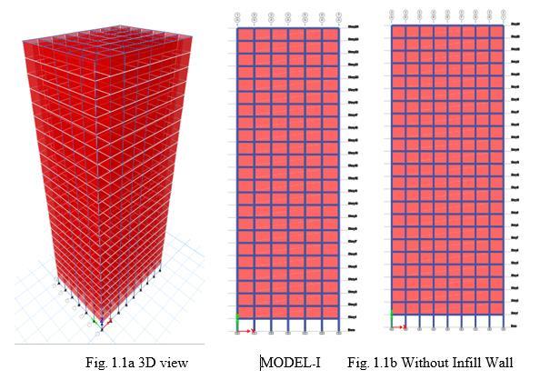
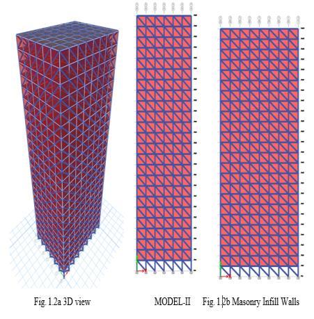
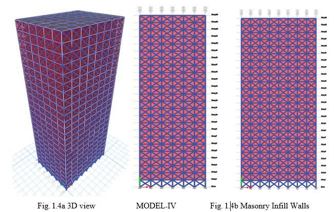
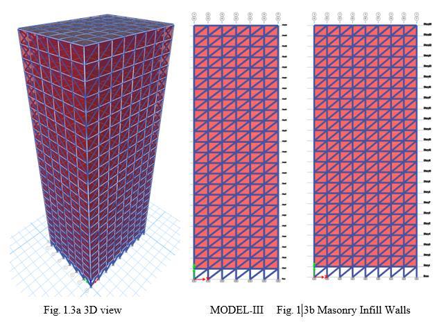
Abstract - In countries like India where seismic activity is widespread, reinforced concrete frames with masonry infill walls are a popular technique. In structural analysis, brick walls are usually considered non-structural elements; only their mass fraction is considered and their structural properties such as strength and stiffness are usually ignored. Structures in seismically active areas are very susceptible to severe damage. In addition to bearing capacity, the structure must withstand lateral loads, which can cause significant stresses. Reinforced concrete frames are the most used building materials in the world today. The frames of a framed structure are often filled with rigid materials such as brick or concrete block, usually to form an envelope. In this research paper, we analyze the structure of a G+23-story rectangular 32mx24 base multi-story building with each floor height of 3.2m and various parameters such as slabthickness of150mm, masonry infill support panel height of 390mm and width of 230mm, external column size 600 mm x 700 mm, internal column size 500 x 600 mm, beam size 500 x 700 mm, with IS code. The four analyzed models, such as Model-I without infill wall structure, Model-II and Model-III are masonry infill walls due to the use of corresponding diagonal support panels such as eccentric rear and eccentric front type, while Model IV diagonal or X -type masonry infill the walls use support panel. In this research, RCC frame structure with and without infill wall is analyzed using Etabs 2021 software and parameters such as seismic zone V, average soil condition, response reduction factor 5, significance factor 1.5 for major building etc. IS-1983. and run four models using the corresponding spectral method with Etabs 2021 software Sum all results in the layer displacement period.
Key Words: RCC Structure, Masonry infill, RCC frame, Seismic analysis, Seismic Zone, Soil Condition, Etabs Software.
Thisfileservesasatemplate,Masonryinfillpanelsarebeing usedintheconstructionofmanyIndianstructuresforboth utilitarianandarchitecturalpurposes.Masonryinfillwalls are often regarded as non-structural elements, and in practice that is, when the building is intended for loading their stiffness components are typically disregarded. But when lateral stresses are placed on the structure,infillwallsofteninteractwiththeframeandalso exhibit energy-dissipating qualities when subjected to seismicloads.Whenlateralloadsareapplied,masonrywalls
maketheinfillmorerigid.Acompositeconstructionmade up of infill walls and a moment-resisting planar frame is referredtoasa"infillframe".
Masonry walls are used to create segregation and/or seclusion in the majority of reinforced concrete frame buildings.Sincetheinfill wall isthoughttobe load-free in conventional practice, its involvement in the analysis and designofthestructureisdisregarded, andtheinfill'sselfweightistakenintoaccountwhendesigningotherstructural components. On the other hand, very high initial lateral stiffness and poor ductility were seen in frames with MI walls. The lateral load transmission mechanism of the structure shifts from a dominating frame action to a dominantlatticeeffectwhentheframesarefilledwithbrick walls.Thiscausesthebendingmomentsandaxialforcesin theframememberstodiminish.
To investigate the structural analysis effects of G +23 layeredstructurewithandwithoutinfillwall.
Toinvestigatetheeffectofmasonryinfillonthestiffness ofthestructure.
1.2 building Plan Configuration
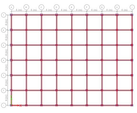
Fig.1.1Plan
International Research Journal of Engineering and Technology (IRJET) e-ISSN: 2395-0056
Volume: 11 Issue: 07 | July 2024 www.irjet.net p-ISSN: 2395-0072
S. Vijayalakshmi, J. Saibaba (2022) - Using the structural analyzer E-TABS, they examined the threedimensional analytical model of the G+10 multi-story building for several building models. All the significant elementsthatinfluencethemass,strength,andstiffnessof the structure are included in the analytical construction
model.Toassessthecapacity,demand,andefficiencyofthe model under discussion, the research combines seismic analysis with non-linear static (push) and linear dynamic (responsespectrumapproach)processes.Despitethebrittle failuremodesofthewall,theyinferfromthethrustanalysis of the models that the initial stiffness and strength of the packed frame rises compared to the bare frame. But comparedtothebareframe,itfailsatacomparativelylower slip threshold. Trupti S. Shewalkar, Amey R. Khedikar (2019) - Using STAAD Pro V8i software, they examined a G+10storeyRCCframebuilding withandwithoutaninfill wall. The support width was manually determined in accordancewiththeFEMA-356provision.Whencomparedto the bare frame, they discovered that the infill had a considerableimpactonthestructureandincreasedrigidity, which helped the building endure the seismic zone. Shriyanshu Swarnkar, Dr. Debarati Datta (2015) - They lookedatvariousdesignsfor4,8,and12storystructuresthat raisedabasebythreetosixonemptyandfilledframes.They then assessed each design using a variety of techniques, including response spectrum analysis, equivalent static method,andnonlinearstaticimpulseanalysis.Inthepusher analysis, it was demonstrated that as the building's height andnumberofopeningsrise,sodoesthebase'sdisplacement capacity.Additionally,thetimeperiodsincreaseintandem withthesedevelopments.Theoverallrigidityofthestructure rises with the number of legs. d) The behavior of the structure turns from ductile to rigid with the addition of fillers.Itisharderforbarestructuresthanforfilledones.
IRJETOpenEtabsSoftware
CreatingModellingofRCbuilding
Applying property like beam, column, slab dimensionandsupportonstructure
ApplyingLoadlikeDeadload,Liveload,seismicload andloadcombinationasperIScode
GettingVariousResults
ResultsAnalysis
Conclusion
RCbuildingswithandwithoutmasonryinfillwallsarethe typeofbuildings.BuildingPlanConfiguration:Floorheight: 3.2meters,24by32metersofG+23Fourmetersseparates thebaysineachdirection,andtherearesixandeightbaysin total.Property:Theouterandinnercolumnsmeasure600by 700mmandthebeams500by700mm,respectively.The thicknessoftheslabis150mm,andthestrutforthemasonry infill walls measures 390 by 230 mm. Seismic Analysis Techniques: Response Spectrum Analysis Building shape: rectangular;numberofmodels:four(twowithandwithout
Volume: 11 Issue: 07 | July 2024 www.irjet.net
infill walls positioned differently). The symmetric seismic parameteristhetypeofstructure.
:MasonryinfillwallsandRCbuildingsarethesametype ofstructure.G+23(abuildingwitharectangularshape)has themostfloors.Formediums,usethesoilsitefactor2and seismiczone-VandzonefactorZ=0.36.soil circumstances, Damping Ratio 5% (according to Table 3 Clause 6.4.2), ImportanceFactorI=1.5(accordingtoTable6'sImportant Structure), Table 7 shows the Response Reduction Factor (R=5)forthespecialsteelmoment-resistantframe.Average coefficientofacceleration(Sa/g)isdependentontheNatural FundamentalPeriod.ThegradesofsteelareFe-345,rebaris gradedFe-415,andconcreteisgradedM25.Deadloadsfor slabsare3.75KN/m2andwallsare14.375KN/m.
Table:4.1 Structural modeling specification of G+Y Buildings
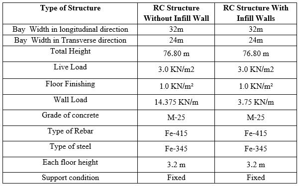
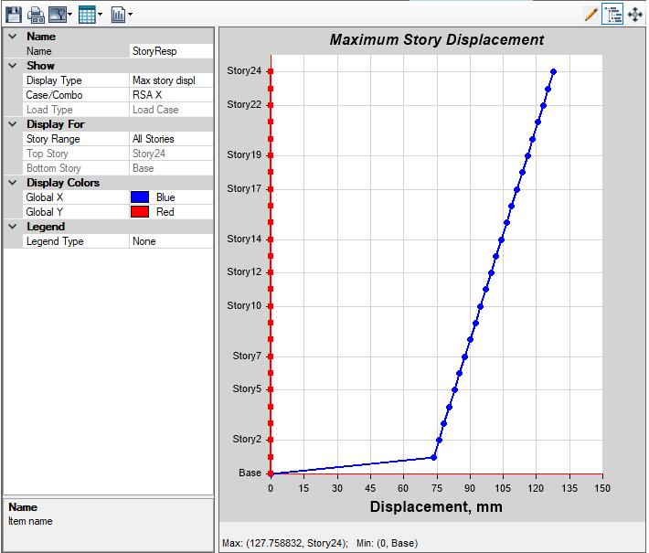
Fig.-5.1MaximumDisplacement(mm)inXdirection
Table-5.1MaximumDisplacement(mm)inXdirection
MODEL-I(G+23), MAXIMUM STOREYDISPACEMENTINXDIRECTIONINMM
Story1
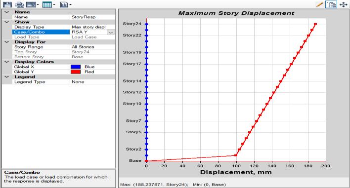
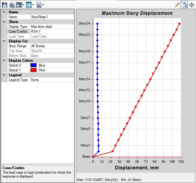
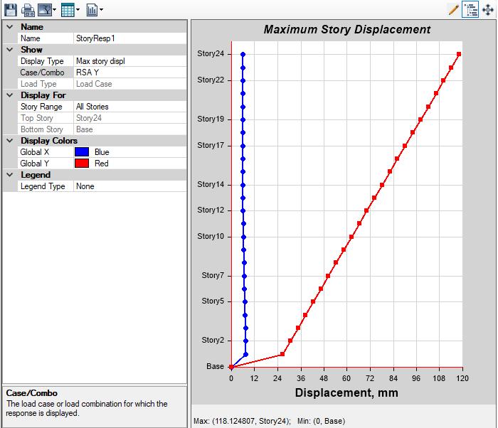
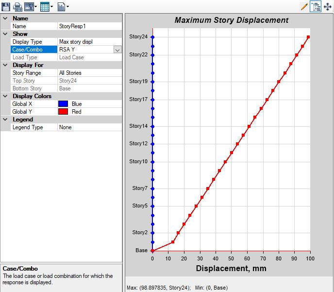
Fig.-5.2MaximumDisplacement(mm)inYdirection
Volume: 11 Issue: 07 | July 2024 www.irjet.net p-ISSN: 2395-0072
Storey
Story24
Story23
Story22
Story21
Story20
Story19
Story18
Story17
Story16
Story15
Story14
Story13
Story12
Story11
Story10
Story7
Story6
Story5
Story4
Story3
Story2
Story1
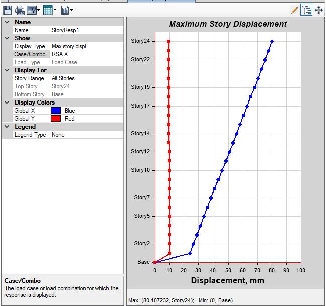
Fig.-5.3
Story23
Story22 704 75215
Story21 672 72768
Story20
Story19
Story18 576 65423
Story17 544 62975
Story16
Story15
Table-5.3MaximumDisplacement(mm)inXdirection Fig.-5.4
Volume: 11 Issue: 07 | July 2024 www.irjet.net
Table-5.4MaximumDisplacement(mm)inYdirection
Story23
Story22
Story21
Story20
Story19
Story16
Story15
Story10
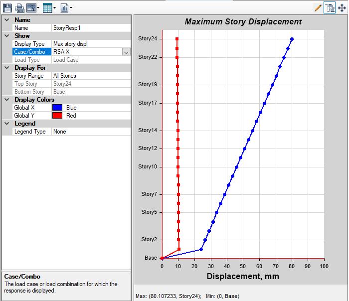
Fig.-5.5
Table-5.5MaximumDisplacement(mm)inXdirection Fig.-5.6
Volume: 11 Issue: 07 | July 2024 www.irjet.net
Table-5.6MaximumDisplacement(mm)inYdirection
Story24
Story23
Story22
Story21
Story20
Story19
Story18
Story17
Story16
Story15
Story14
Story13
Story12
Story10
Story5
Story2
Story1
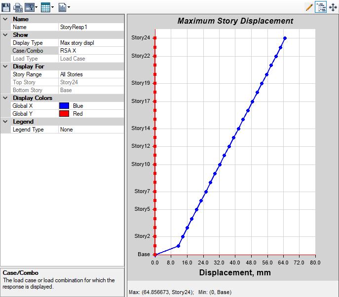
Fig.-5.7
Table-5.7MaximumDisplacement(mm)inXdirection Fig.-5.8
International Research Journal of Engineering and Technology (IRJET) e-ISSN: 2395-0056
Volume: 11 Issue: 07 | July 2024 www.irjet.net p-ISSN: 2395-0072
Table-5.8MaximumDisplacement(mm)inYdirection
MODEL-IV(G+23), MAXIMUM STOREYDISPACEMENTINYDIRECTIONINMM
Storey StoreyHeight(m) Displacement(mm)
Story24 768 98898
Story23 736 95139
Story22 704 91379
Story21 672 87618
Story20 64 83856
Story19 608 80093
Story18 576 7633
Story17 544 72567
Story16 512 68804
Story15 48 65042
Story14 448 6128
Story13 416 57521
Story12 384 53763
Story11 352 50007
Story10 32 46254
Story9
Story8 256 38759
Story7 224 35018
Story6 192 31283
Story5 16 27555
Story4 128 23835
Story3 96 20127
Story2 64 16435
Story1 32 12771
The findings indicate that the highest storey displacementismeasuredatthetopstoreyofthe Model-IwithoutaMasonryinfillstructure,80.107 mmintheModels-II&IIIofMasonryinfillstructure as strut eccentric back and eccentric forward as samedisplacement,and64.857mmintheModel-IV withmasonryinfillandXtypeofstrut.Thelowest displacementismeasuredatthefirststoreyofeach Modelat73.539mm,24.007mm,24.007mm,and 11.459 mm, respectively, along the X direction. There is zero displacement at the base of the structurealongtheXdirection.
When comparing all the models, Model I's top storeydisplacementis127.759mmwithoutaninfill structure,whileModelIV'sMasonryinfillstructure with X type struts has a minimum storey displacementof11.459mm.Thisindicatesthatthe ideal construction to provide the least amount of storey displacement is a masonry infill structure, particularlyanX-typestrut.
The findings indicate that the highest storey displacementisdetectedatthetopstoreyofModelIwithoutaMasonryinfillstructure,188.238mmin Model-II&Model-IIIofMasonryinfillstructureas struteccentricbackandeccentricforwardassame displacement, and 98.898 mm in Model-IV with masonryinfillwithXtypeofstrut.Meanwhile,the lowestdisplacementisfoundatthefirststoreyof each Model, 26.708 mm, and 12.771 mm, respectively,andthereiszerodisplacementatthe baseofthestructurealongtheYdirection.
When comparing all the models, the Model-I structure with no infill structure has the largest displacement at the top storey of 188.238 mm, whiletheModel-IVstructurewithaMasonryinfill structureofXkindofStruthasthesmalleststorey displacementof98.898mm.Thisindicatesthatthe ideal construction to provide the least amount of storey displacement is a masonry infill structure, particularlyanX-typestrut.
[1] Trupti S. Shewalkar and Amey R, Khedikar, “Performance Analysis of in filled RC Frames in Earthquake Region Using STAAD.Pro” IOSR Journal of Engineering(IOSRJEN)ISSN(e):2250-3021,ISSN(p): 2278-8719PP66-69
[2] Shriyanshu Swarnkar and Dr. Debarati- “Analysis of BuildingwithInfillWalls”JournalofCivilEngineering andEnvironmentalTechnologyPrintISSN:2349-8404; OnlineISSN:2349-879X;Volume2,Number9;April–June,2015pp71–76KrishiSanskritiPublications.
[3] Mohd Abdul Malik , M A Azeem , Mohd Nazim Raza-“ Effect of Infill Walls on Seismic Performance of RC Frames” - International Journal of Research and Scientific Innovation (IJRSI) | Volume V, Issue II, February2018|ISSN2321–2705
[4] Kiran Tidke , Sneha Jangave-“Seismic Analysis of Building with and Without Infill Wall” - International JournalofInnovativeResearchinScience,Engineering and Technology (An ISO 3297: 2007 Certified Organization)Vol.5,Issue7,July2016.
International Research Journal of Engineering and Technology (IRJET) e-ISSN: 2395-0056
[5] S.N. Jaya Kumar, Dr. J. Rex-“Studies On Seismic Resistance Of Rcc Frames With And Without Infill Walls” - Journal of Applied Science and Computations VolumeVI,IssueVI,JUNE/2019ISSNNO:1076-5131
[6] IS1893(Part1):2002”CriteriaforEarthquakeResistant Design Of Structures Part 1 General Provisions and Buildings (Fifth Revision) Bureau of Indian Standards NewDelhi
Volume: 11 Issue: 07 | July 2024 www.irjet.net p-ISSN: 2395-0072 © 2024, IRJET | Impact Factor value: 8.226 | ISO 9001:2008
|