
International Research Journal of Engineering and Technology (IRJET) e-ISSN: 2395-0056
Volume: 11 Issue: 07 | July 2024 www.irjet.net p-ISSN: 2395-0072

International Research Journal of Engineering and Technology (IRJET) e-ISSN: 2395-0056
Volume: 11 Issue: 07 | July 2024 www.irjet.net p-ISSN: 2395-0072
Sumer S Sutar, Ravindra M Desai
P.G Student of Sanjay Ghodawat university, Assistant Professor of Sanjay Ghodawat university. Department of civil Engineering, Sanjay Ghodawat University college, Maharastra, India.
Abstract - Concrete-Filled Steel Tubes (CFST) represent a hybrid structural system that effectively combines the compressivestrengthofconcretewiththetensilestrengthand ductility of steel. This composite action results in enhanced structural performance, making CFST columns increasingly popularinmodernconstructionapplications, suchasbridges, high-rise buildings, and infrastructure in seismic zones. This paper reviews the extensive research conducted on CFST sections, focusing on their mechanical properties, design methodologies, and applications. Experimental studies on CFSTcolumns,consideringparameterslikelength-to-diameter (L/D) ratio, diameter-to-thickness (D/t) ratio, and steel tube thickness, are discussed to evaluate their axial load-carrying capacity under gravity and lateral loading. The experimental results demonstrate the superior performance of CFST columns compared to conventional steel tubes, highlighting their increased strength, ductility, and stiffness. Advanced numerical modeling techniques and code compliance with standards such as Eurocode 4, ACI, AISC, and Australian standardsareexplored. Thepaperconcludesbydiscussingthe future potential of CFST in sustainable and resilient constructionpractices,consideringadvancementsinmaterials science and construction technologies.
Key Words: CFST, Concrete, Column, Testing, Curing, HST, compound, UTM.
CFSTstandsfor"Concrete-FilledSteel Tube."It'satypeof composite structure where a steel tube is filled with concrete. This combination takes advantage of the high compressivestrengthofconcreteandthehightensileand flexuralstrengthofsteel.CFSTstructuresarewidelyusedin civil engineering for various applications such as bridges, columns, and piles. The introduction of CFST technology revolutionized structural engineering by offering several advantages over traditional construction materials and techniques. However,itwasn'tuntil themid-20thcentury thatCFSTgainedwidespreadrecognitionandacceptancein thefieldofstructuralengineering
improvedstructuralperformance.UnderstandinghowCFSTs behaveunderdifferentloadsallowsdesignerstooptimize
theirdesignsforgreaterstrength,stability,anddurability. Seismic resistance CFST are a popular alternative for earthquake-prone areas due to their outstanding seismic performance.Studyingtheir behaviorunderseismicloads leadstosaferdesigns.FireresistanceCFST'sfireresistance is crucial for building safety. Researching their behaviour underfirecircumstancesaidsinthedevelopmentofbetter fire-resistant structures. Sustainability CFST provides reducedmaterialusageandincreasedstructuralefficiency, making it a sustainable solution. The study of their environmental impact aids in the development of more environmentally friendly designs. Innovative applications. The adaptability of CFST enables novel applications in offshore structures, bridges, and high-rise buildings. Researchingtheirbehaviorinthesecircumstancesbroadens theirpossibilities.
Concrete-FilledSteelTube(CFST)technologyhasnumerous uses in civil engineering and construction. Some of the importantapplicationsare:
Bridgebuilding:CFSTelementsarefrequentlyutilizedinthe building of bridge piers, abutments, and other structural components.CFSTbridgepiersprovideincreasedstrength, longevity, and seismic resistance, making them suited for highwayandrailwaybridges.High-risestructuresuseCFST columnsandstructuralelementsbecausetheyhaveahigher load-carryingcapacity,aremorefireresistant,andperform better seismically. CFST technology enables taller, more slender building designs while maintaining structural integrity and safety. maritime Structures: CFST piles are commonly used to construct maritime structures such as wharves, jetties, and offshore platforms. CFST piles have goodcorrosionresistanceandload-bearingcapacity,making them ideal for maritime situations. Retaining walls and excavationsupportsystemsareconstructedwithCFSTsheet pilesincivilengineeringprojects.
International Research Journal of Engineering and Technology (IRJET) e-ISSN: 2395-0056
Volume: 11 Issue: 07 | July 2024 www.irjet.net p-ISSN: 2395-0072
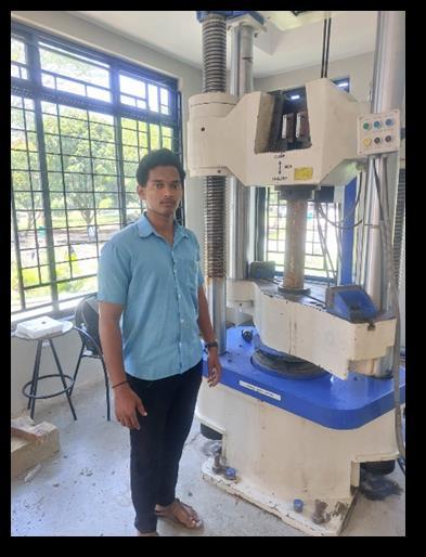
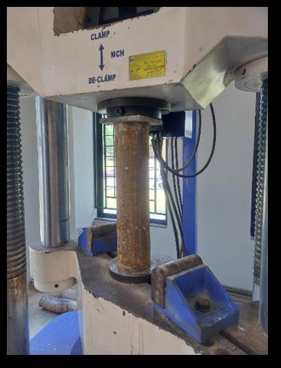
2. Experiment
Table -1: Detailsofcolumnspecimens
8
9 CFST1Circular
10 CSFT2Circular
3 M30
3 M30
To calculate the axial load-carrying capacity of the CFST column, we can use the following analytical formula: Eurocode 4 (EN 1994-1-1:2004)
NRd=(A_sxf_yd)+(A_cxf_cd)
Where:
-NRd=Axialload-carryingcapacity
-A_s=Cross-sectionalareaofthesteeltube
-f_yd=Designyieldstrengthofsteel(assuming310MPa)
-A_c=Cross-sectionalareaoftheconcretecore
-f_cd=Designcompressivestrengthofconcrete(assuming 30MPa)
Given:
-Diameter(D):100mm
-Thickness(t):3.75mm
Calculate:
-A_s=π/4×(100^2-92.8^2)=1090.25mm^2aspersteel table1250mm2
-A_c=π/4×(92.8)^2=6763.72mm^2
Now,substitutethevaluesintotheformula:
NRd=(1250x269.56)+(6763.72x20)
=336950+135274.4
=472224.4N
Therefore, the axial load-carrying capacity of the CFST columnisapproximately472224.4NOR472.23KN.
Note:Thevaluesusedare:
-f_yd=310MPa(yieldstrengthofsteel)310/1.15=269.56 mpa
- f_cd = 30 MPa (compressive strength of concrete) 30/1.5=20mpa
To calculate the axial load-carrying capacity of the CFST column, we can use the following analytical formula: Eurocode 4 (EN 1994-1-1:2004)
NRd=(A_sxf_yd)+(A_cxf_cd)
Where:
-NRd=Axialload-carryingcapacity
-A_s=Cross-sectionalareaofthesteeltube
-f_yd=Designyieldstrengthofsteel(assuming345MPa)
-A_c=Cross-sectionalareaoftheconcretecore
-f_cd=Designcompressivestrengthofconcrete(assuming 30MPa)
Given:
-Squarecolumn:100mmx100mm
-Thickness(t):3.75mm
Calculate:
-A_s=(100x100)-(92)^2)=1536mm^2aspersteeltable 1495mm2.
-A_c=(92x92)=8464mm^2
Now,substitutethevaluesintotheformula:
NRd=(1495x269.56)+(8464x20)
=402992.2+169280
=572272.2N
Therefore, the axial load-carrying capacity of the CFST columnisapproximately572272.2Nor572.28KN.
Note:Thevaluesusedare:
International Research Journal of Engineering and Technology (IRJET) e-ISSN: 2395-0056
Volume: 11 Issue: 07 | July 2024 www.irjet.net p-ISSN: 2395-0072
-f_yd=310MPa(yieldstrengthofsteel)310/1.15=269.56 mpa
- f_cd = 30 MPa (compressive strength of concrete) 30/1.5=20mpa
The analytical axial load carrying capacity of a ConcreteFilled Tube (CFT) column can be calculated using the following formula: (AISC) design guidelines
P₀=0.85[0.78(1-A₁/A₂)+0.22(fₓₗ/fₓₒ)]fₓₒA₂
Where:
-P₀=Axialloadcarryingcapacity
-A₁=Cross-sectionalareaofthesteeltube
-A₂=Cross-sectionalareaoftheconcretecore
-fₓₗ=Yieldstrengthofthesteeltube
-fₓₒ=Compressivestrengthoftheconcretecore
This formula is based on the American Institute of Steel Construction(AISC)designguidelinesforCFTcolumnsand takesintoaccountthecompositeactionbetweenthesteel tubeandtheconcretecore.
Note:Thisisasimplifiedformulaandadditionalfactorssuch asslendernessratio,eccentricity,andlocalbucklingshould beconsideredforamoreaccuratecalculation.
Also, it's important to note that this formula is for a concentrically loaded CFT column, if the load is eccentric, additionalcalculationsareneededtoaccountforthebending moment.
It's always recommended to consult the relevant design codesandguidelines,suchasAISC,ACI,orEurocode,andto perform a detailed analysis with the help of a structural engineeringsoftwareorconsultwithastructuralengineer foramoreaccurateandsafedesign.
Table no -2 Results
International Research Journal of Engineering and Technology (IRJET) e-ISSN: 2395-0056
Volume: 11 Issue: 07 | July 2024 www.irjet.net p-ISSN: 2395-0072
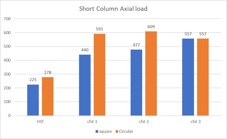
Fig no -3 shows Square and circular axial load carrying capacitybyshortcolumn.
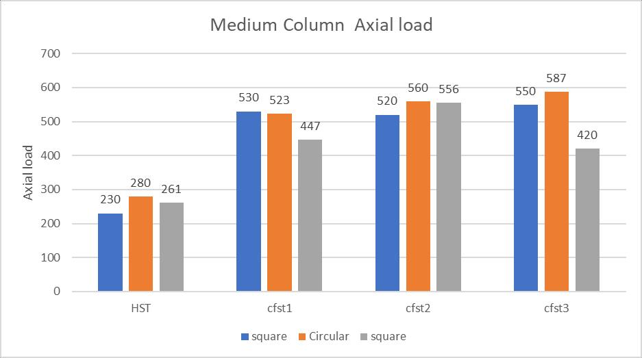
Fig no -4 Medium column Axial load
Fig no-4 shows Square and circular column Axial load carryingcapacitybymediumcolumn.
3. CONCLUSIONS
Aconclusionisafinalsectionofastudy,paper,orreportthat summarizes the key findings, implications, and recommendationsderivedfromtheresearch.Itprovidesa concise overview of the primary results and their significance, often highlighting the practical applications, contributions to the field, and potential areas for future
research. The conclusion aims to bring closure to the researchbyreinforcingthemainpointsandofferinginsights orguidancebasedontheevidencepresented.
1) The axial load carrying capacity of square column experimentalvalueis473.79KNandcalculatedbyAnalytical methodbyuseAISCformulais631.80KNanduseEurocode 4 (EN 1994-1-1:2004) value is 5725.28 KN .M30 grade of concreterespectively.
2) Square column CFST increased axial load carrying capacityis46.4%comparedbyHSTcolumn.
3) The axial load carrying capacity of circular column experimentalvalueis585.66KNandcalculatedbyAnalytical methodbyAISCformulais496.22KNanduseEurocode4 (EN 1994-1-1:2004) value is 472.23 KN. M30 grade of concreterespectively.
4) Circular column CFST increased axial load carrying capacityis58.56%comparedbyHSTcolumn.
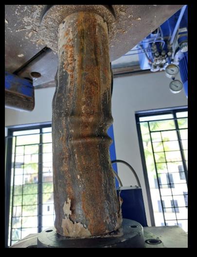
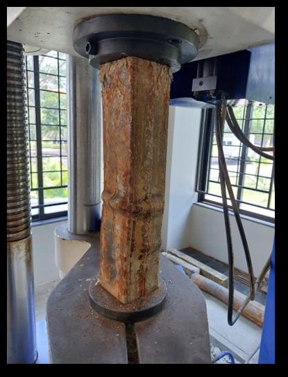
5)ThefailureoftheCFSTcolumnswasbasicallyduetothe localbucklingnearthemidheightcomparestothefailureof Hollow Steel Tubular columns which failed due to local bucklingneartheends.
1)Researchersandengineershavesubstantiallyexpanded the scope of CFT with the rapid expansion of study and application of CFT structures all over the world.
2)OneofthecharacteristicsofCFTistheabilitytoimprove structural qualities through the composite action of steel tube and filled concrete.
3) CFST can be used as an alternative to the steel or RC system.
4) Studies on the CFT system's adaptability should be thoroughlystudiedinordertobroadenitsusesinthefuture.
5)Innovativeapplications:TheadaptabilityofCFSTmakesit suitableforusageinoffshorestructures,bridges,andhighrise buildings. Researching their behavior in these circumstancesbroadenstheirpossibilities.
6) Advances in construction technology: CFST research promotes innovation in construction materials and procedures,propellingtheindustryforward.
1]Kilpatrick,A.E.,andRangan,B.V.March1997."Testson High-Strength Composite Concrete Columns" Research Report No.1/97, School of Civil Engineering, Curtin University of Technology, Perth, Western Australia.
[2]. Dallaire, E., Aitcin, P., and Lachemi, M., "HighPerformancePowder,"CivilEngineering,January1998,pp. 49-51.
[3]. Zhong. 1988. "The Development of Concrete Filled Tubular Structures in China", Proceedings of the International Conference on Concrete Filled Steel Tubular Structures,China.S
International Research Journal of Engineering and Technology (IRJET) e-ISSN: 2395-0056
Volume: 11 Issue: 07 | July 2024 www.irjet.net p-ISSN: 2395-0072
[4] Han LH, Ren QX, Li W, 2011, "Tests on stub stainless steel-concrete-carbon steel double skin tubular (DST) columns".JournalofConstructionalSteelResearch,67(3),pp 437–52.
[5]HanLH,ZhengLQ,HeSH,TaoZ,2011."Testsoncurved concrete filled steel tubular members subjected to axial compression." Journal of Constructional Steel Research, 67(6),pages965-76.
[6] Han LH, He SH, Liao FY, 2011. "Performance and calculationsofconcretefilledsteeltubes(CFST)underaxial tension."JournalofConstructionalSteelResearch,67(11), pp.1699-709.
[7]. Han LH, 2004, "Flexural behaviour of concrete-filled steeltubes,"JournalofConstructionalSteelResearch,60(2), pp.313–37.
[8]ShedehGhannam,HamidR.Al-Ani,andOrabi-Al-Rawi, 2010,"Comparativestudyofloadcarryingcapacityofsteel tube filled light weight concrete and normal concrete," JordanJournalofCivilEngineering,vol.4,no.2,pp.164–169.
[9]. 11. J. Zeghiche and K. Chaoui, 2005, "An experimental behaviourofconcretefilledsteeltubularcolumns,"Journal ofConstructionalSteelResearch,number61,pp53-66.
[10] Muhammad Naseem Baig, FAN Jiansheng, and NIE Jianguo, 2006, "Strength of concrete filled steel tubular columns," Tsinghua Science andTechnology,vol 11, no. 6, pp.657–666.
[11].LanhuiGuo,SumeiZhang,Wha-JungKim,andGianluca Ranzi, "Behaviour of Hollow Steel Tubes and Steel Tubes FilledwithConcrete,"(www.elsevier.com),issue45,pp961–973.
[12]EKMohanraj,SKandasamy,andARajaraman,2007. "Seismicbehaviourofconcretefilledsteeltubularbeams," 35th conference on OUR WORLD IN CONCRETE AND STRUCTURES.
[13]ArivalaganandKandasamy,2009,"Energyabsorption capacity of composite beams," Journal of Engineering ScienceandTechnology,vol2,no.1,pp.145–150.
14) Han LH, Ren QX, and Li W. (2011) "Tests on stub stainless steel-concrete-carbon steel double skin tubular (DST)columns" Journal ofConstructional Steel Research, 67(3),437–52.
15) Dallaire, E., Aitein, P., and Lachemi, M. "HighPerformancePowder."CivilEngineering,January1998,pp. 49–51.
2024, IRJET | Impact Factor value: 8.226 |
|