
International Research Journal of Engineering and Technology (IRJET) e-ISSN: 2395-0056
Volume: 11 Issue: 07 | July 2024 www.irjet.net p-ISSN: 2395-0072

International Research Journal of Engineering and Technology (IRJET) e-ISSN: 2395-0056
Volume: 11 Issue: 07 | July 2024 www.irjet.net p-ISSN: 2395-0072
1P.G Student, Department of Civil Engineering, U.V.C.E, Bangalore University, Bengaluru
2Associate Professor, Department of Civil Engineering, U.V.C.E, Bangalore University, Bengaluru
Abstract - Earthquakes can inflict damage not only through direct vibrations but also through secondary effects such as landslides, floods, and fires. The response of a building during an earthquake largely depends on its overall shape, size, geometry, and the impact of seismic forces on the ground. Reinforced concrete (RC) multi-story buildings are generally designed to withstand both vertical and horizontal loads. Shear walls, which are structural elements used to counteract horizontal forces, play a crucial role in this regard. With their high stiffness and strength, shear walls can resist significant horizontal loads while also supporting gravity loads, making them essential for both economic efficiency and controlling horizontal displacement. This study examines the effect of shear wall placement on seismic load resistance. Finite Element (FE) analysis is performed on a G+13 RC building to evaluate various shear wall configurations. Results from the Response Spectrum Analysis include natural time period, base shear, story displacement, and story drift
Key Words: Earthquake, Geometry of the structure, Shear wall, Horizontal Displacement, FE analysis, Natural time period, Base shear, Storey displacement and Storey drift.
Anearthquakeisasuddenshakingofthegroundcausedby thepassageofseismicwaves.EarthquakeGroundMotions (EQGMs) transfer significant energy to structures, making them highly vulnerable to sudden damage. Consequently, designing structures to minimize vibrations caused by earthquakeshasbeenalongstandingconcernforstructural engineers. Reinforced Concrete (RC) buildings often incorporate vertical plate-like RC walls known as shear walls.Theseshearwallsarespecificallyengineeredtoresist horizontalforcesinducedintheplaneofthewallfromwind, earthquakes, and other forces. Therefore, buildings When buildings are designed without shear walls, the sizes of beamsandcolumnsneedtobesignificantlylarger,whichcan leadtoissuesatthejoints.Theselargerstructuralelements cancausecongestionincertainareas,makingitchallenging toproperlyvibratetheconcrete,andresultinginnoticeable displacement. This increased displacement can, in turn, inducesubstantialforceswithinthebuilding'smembers.In such cases, incorporating shear walls becomes crucial for botheconomicefficiencyandeffectivecontrolofhorizontal displacement.
Inadditiontobeamsandcolumns,ReinforcedConcrete (RC)buildingscommonlyincludevertical,plate-likeRC wallsknownasshearwalls.Theseshearwallstypically extend from the foundation level to the top of the building. Their thickness can range from 150mm to 400mm in moderate to high-rise structures. Functioninglikeverticallyorientedwidebeams,shear wallsarestrategicallyplacedalongboththelengthand widthofthebuilding.
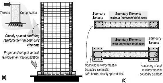
Fig-1:
Shear walls are straightforward to construct due to their simple reinforcement detailing, which can be easily implemented on site. They are both cost-effective and efficient in reducing earthquake damage to structural and non-structural elements. Shear walls typically have an oblongcross-section,whereonedimensionismuchlarger than the other. While rectangular cross-sections are common,L- andU-shapedsectionsarealsoutilized. Thinwalled hollow RC shafts around elevator cores can also function as shear walls and should be utilized to resist earthquake forces. Steel reinforcing bars are arranged in regularlyspacedverticalandhorizontalgridswithinthese walls,oftenorganizedintooneortwoparallellayers,known ascurtains.Horizontalreinforcementmustbeanchoredto theendsofthewalls,andtheminimumareaofreinforcing steelshouldbe0.0025timesthecross-sectionalareainboth horizontal and vertical directions. This vertical reinforcementshouldbeevenlydistributedacrossthewall’s cross-section.
International Research Journal of Engineering and Technology (IRJET) e-ISSN: 2395-0056
Volume: 11 Issue: 07 | July 2024 www.irjet.net p-ISSN: 2395-0072
A shear wall resists loads that are parallel to its plane. Collectors, also known as drag members, transfer the diaphragmsheartoshearwallsandotherverticalelementsof the seismic force-resisting system. Shear walls can be constructedfromvariousmaterials,includinglight-framedor braced wooden walls with thin shear-resisting panels, reinforcedconcretewalls,reinforcedmasonrywalls,orsteel plates
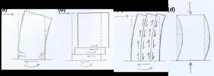
Fig-2: Failuremechanismsofshearwalls.
(a)Flexuralfailure,(b)Horizontalshear,(c)Vertical shear,(d)buckling
Ashearwallisstifferalongitsprincipalaxiscomparedtothe other axis. It functions as a primary structural element, providing significant resistance to both vertical and horizontal forces acting within its plane. Under these combined loading conditions, a shear wall experiences complex internal stress distributions due to axial, shear, torsional, and flexural strains. This allows for the vertical transferofloadstothebuilding'sfoundation.Consequently, therearefourcriticalfailuremechanisms,asillustratedin Fig-2.Factorsinfluencingthesefailuremechanismsinclude thewall'sgeometry,loadingconditions,materialproperties, restraint,andconstructiontechniques.Shearwallscanalso be constructed using light-gauge steel diagonal bracing members, which are connected to collectors and anchor points.
Variousstudieshavebeenconductedbydifferentauthors, leadingtovariousconclusions.Thesestudiesofteninvolve creating3Dbuildingmodelsforbothlinearstaticandlinear dynamic analyses, as well as examining the impact of incorporatingaconcretecorewallatthebuilding'scenter. These analyses compare different models to assess performanceundervariousconditions.
Placingashearwallatthecenterofabuilding,alongwith fourshearwallspositionedattheouteredgesparalleltothe XandYdirections,resultsinmaximumbaseshear,reduced displacement, and minimized inter-story drift in both equivalent static and response spectrum analyses, particularly in the longitudinal direction. The presence of shear walls enhances the strength and stiffness of the
structure(ShahzadJamilSardarandUmeshN.Karadi).Itis observedthatbaseshearanddisplacementaregreateralong the slope compared to the transverse direction. Among various configurations, straight or rectangular shear wall arrangements are generally more effective in resisting lateral displacement. However, during seismic events, Lshaped configurations can be particularly advantageous (PawarS.P.).
The earthquake-resistant performance of a building improves with the strategic placement of shear walls, particularly when they are centrally located and symmetricallyarranged.Nevertheless,insomecases,lateral displacements may still be minimal. Additionally, plan irregularity plays a significant role in seismic evaluation (TabarejAlam).
This chapter outlines the structural models used in this study, providing a comprehensive summary of the parametersconsideredforanalyzingthepositioningofshear wallsinresistingseismicloads.Itincludesdetailsontheplan for each respective model. The chapter also explains the methodology employed to compute these parameters and highlights key features of the current provisions for earthquake-resistant design in reinforced concrete lateral force-resistingsystems.
Acomprehensiveliteraturereviewisconductedtoexamine thepositioningofshearwallsinresistingseismicloadsand todevelopResponseSpectraforallseismiczonesaccording toIS: 1893(Part-1):2016. Thestudyinvolves performing modalanalysisonaG+13RCstructurewithvariousshear wallconfigurationstodeterminetheTimePeriodandmode shapes. Additionally, Equivalent Static and Response SpectrumAnalysesarecarriedouttocalculateStaticBase Shear, Dynamic Base Shear, Scale Factor, Corrected Base Shear,Displacement,andStoreyDrift.Theresultsfromthe modalanalysisarecomparedwiththeTimePeriodformulae providedinIS:1893(Part-1):2016.AllFiniteElement(FE) analysisresultsarepresentedintabulatedform,discussed, andusedtodrawconclusions.
2.2 Material properties considered for analysis.
Thepresentstudyadoptsstructural3Dmodelswithdifferent positioning of the shear wall placed in the RC structure is mentioned. The seismic response of these models with different shear wall position is compared with the regular frame system RC structure model. The base plan size has been kept as 25m x 25m. The structural configuration are shown in Table-1 and model nomenclature are shown in Table-2.
International Research Journal of Engineering and Technology (IRJET) e-ISSN: 2395-0056
Volume: 11 Issue: 07 | July 2024 www.irjet.net p-ISSN: 2395-0072
Table -1: Structuralconfiguration
Description Data
Typeofstructure
structure
GradeofConcrete(fck ) M30
GradeofReinforcingSteel(fyr) Fe500
Numberofstoreys G+13
StoreytostoreyHeight 3.0m
BaytoBayDistance
ColumnSizeused 600x600
BeamSizeused 300x450
Thicknessofslab 150mm
Liveload 3kN/m2
FloorFinishLoad 1.5kN/m2
SeismicZone V
SeismicZoneFactor(Z)
Importance
Soil
LoadCombination
1. 1.5(DL+LL) 2. 1.2(DL+LL+E Q)
3. 1.5(DL+EQ) 4. 0.9DL+EQ
Table -2: Buildingnomenclature
RCBF RCstructurewithoutshearwall.
RCSW RC structurewith shearwall forallthe floors.
RCSWUH RC structurewith shearwall forupper halfofitsheight.
RCSWLH RC structurewith shearwall forlower halfofitsheight
RCSWUL3 RC structure with shear wall atupper andlowerh/3
RCSWM3 RC structure with shear wall atmiddle h/3.
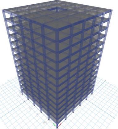
3:
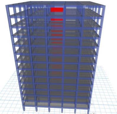
4: 3D view of
International Research Journal of Engineering and Technology (IRJET) e-ISSN: 2395-0056
Volume: 11 Issue: 07 | July 2024 www.irjet.net p-ISSN: 2395-0072
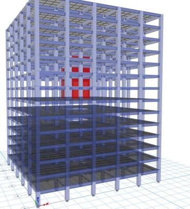
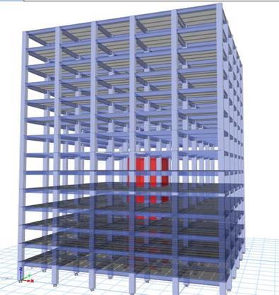
Table 3.1: Time Period (sec)
0 IS Code RCBF RCSW RCSWUH RCSWLHRCSWUL3RCSWM3 Building models
Fig 7: Time period(s)
Table 3.2 Dynamic Base Shear (kN)
International Research Journal of Engineering and Technology (IRJET) e-ISSN: 2395-0056
Volume: 11 Issue: 07 | July 2024 www.irjet.net p-ISSN: 2395-0072
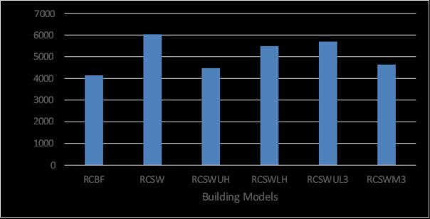
8: Dynamic base shear (kN)
Table 3.3 Storey Displacement (mm) of G+13 building
Table 3.4 Storey drift (10-4 mm) of G+13 building
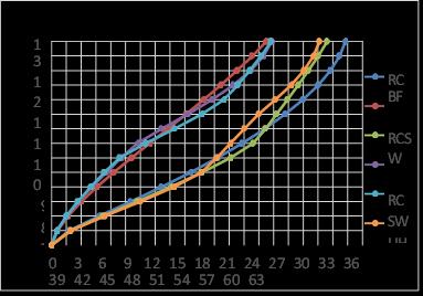
9: Storey Displacement(mm)
Fig 10: Storey drift 4. CONCLUSIONS
➢ TimePeriodofRCstructurewithcompleteshear wall is less compared to other models due to increaseinstiffness.
➢ TimePeriodofRCstructurewithcompleteshear wallis50%less,whencomparedtoRCbareframe structureduetoincreaseinstiffness.
➢ TimeperiodofRC structurewithshear wall for upperhalfofitsheightis24%more,comparedto RCstructurewithshearwallforlowerhalfofits heightduetoinfluenceofmass.
International Research Journal of Engineering and Technology (IRJET) e-ISSN: 2395-0056
Volume: 11 Issue: 07 | July 2024 www.irjet.net p-ISSN: 2395-0072
➢ Time period of RC structure with shear wall at upperandlowerh/3is23%less,comparedtoRC structure with shear wall at middle h/3 due to increaseinstiffness.
➢ BaseshearismaximumfortheRCstructurewith completeshearwallcomparedtoallothermodels duetohigherself-weight.
➢ Base shear of RC structure with complete shear wall is more with 31%, compared to RC bare framestructure,duetoincreaseinitsweight.
➢ Base shear of RC structure with shear wall at upper and lower h/3 is more with 19%, compared to RC structure with shear wall at middleh/3,duetoincreaseinitsweight.
➢ Base shear of RC structure with complete shear wall is31%morecompared tobareframe,26% moreinstructurewithshearwallforupperhalfof itsheight,9%moreinstructurewithshearwallfor lowerhalfofitsheight,6%moreforthestructure for upper and lower h/3, and 23% more for structurewithshearwallatmiddleh/3.
➢ RCstructurewithcompleteshearwallshowsthe minimumdisplacementcomparedtoothercases duetoincreaseinthestiffness.
➢ RC Bare Frame Structure is more displaced compared to other RC structure with complete shear wall and without shear wall at different positions due to ductility in the bare frame and lowerself-weight.
➢ Alldisplacementsarewithinthepermissiblelimit ofh/500
➢ DisplacementofRCstructurewithoutshearwallis more with 27%, compared to RC bare frame structure.
➢ DisplacementofRCstructurewithshearwallfor upper half of its height is more with 20%, compared to RC structure with shear wall for lowerhalfofitsheight.
➢ Displacement of RC structure with shear wall at middle h/3 is more with 18% , compared toRC structure withshearwallatupperandlowerh/3 duetoincreaseinitsductility.
➢ DisplacementofRCstructurewithcompleteshear wallis37%lesscomparedtobareframe,28%less instructure with shear wall for upperhalfofits height, 3% less in structure with shear wall for lowerhalfofitsheight,2%lessforthestructurefor
upperandlowerh/3,and25%lessforstructure withshearwallatmiddleh/3.
➢ Storey drift for all the cases are within the permissiblelimitof0.004h(hisstoreyheight)as perIS1893(Part-1)2016.
➢ Storey drift is reduced in all the Structures compare with RC structure with shear wall at middleh/3.0
1. Desale D.S, Kankariya C.S, V. N. Kanthe V.N(2022),“EffectofPositionsandOrientationsofShear Wall in Structure”, International Journal of Advanced Research in Science, Communication and Technology,February2022,vol2,pgno.557-565
2. Gajagantarao Sai Kumar1, Purushotham Rao, Partheepan Ganesan(2021), “Effect of Shear Wall Location On Seismic Performance of High Raised Buildings”, International Journal of Research in Engineering,ScienceandManagement,January2021,vol 4,pgno-30-34
3. Israa H. Nayel, Shereen Q. Abdulridha, Zahraa M. Kadhum(2018),“TheEffectOfShearWallLocations In RC Multistorey Building With Floating Column Subjected To SeismicLoad”,InternationalJournalOfCivilEngineeringand Technology,July2018,Vol9,PgNo.642-651
4. KajalPatil,ShendeT.G(2022),“AComparativeStud yOfDifferentShapesOfShear Wall In Asymmetrical Building On Different Slopping Ground”, International Journal On Creative Research Thoughts, June 2022,Vol 10,Pg.No409-419
5. Krishnan P.A, Anjaly Francis, Pradeep V.N(2019), “Effect Of Location Of Shear Wall On Buildings Subjected To Seismic Loading” International JournalOfEngineeringResearchAndManagement”,July 2019,Vol.6,PgNo.34-37
6. ManaliS.Jajoo,Dr.M.R.Shiyekar(2022),“Effective PositioningOfShearWall For High Rise Building”, International Research Journal Of Modernization In EngineeringTechnologyAndScience,Vol.4,Pg.No11271132
7. PawarS.P(2016),“EffectOfPositioningOfRCShearw allsOfDifferentShapesOn Seismic Performance Of Building Resting On Sloping Ground”, International Journal Of Civil Engineering And Technology , Volume 7,PgNo.373-384
International Research Journal of Engineering and Technology (IRJET) e-ISSN: 2395-0056
Volume: 11 Issue: 07 | July 2024 www.irjet.net p-ISSN: 2395-0072
8. Shahzad Jamil Sardar and Umesh. N. Karadi
(2013), “Effect Of Change In Shear Wall Location On StoreyDriftOfMultistoreyBuildingSubjectedToLateral Loads”,InternationalJournalOfInnovativeResearchIn Science,EngineeringAndTechnology,September2013, Vol.2,Issue9,PgNo.4241-4249
9. TabarejAlam,RajivBanerjee,OvaisbinDawood, MohdMohsinKhan,Neeraj Kumar Singh(2023), “A Review On Effect Of The Positioning Of ShearWall For Earthquake Resistance Multi-Story building, International journal on creative research thoughts”,April2023,Vol11,PgNo51-56
10. Titiksh A, Bhatt G(2017), “OptimumPositioning Of ShearWalls For Minimizing The Effects Of Lateral Forces In Multistorey-Buildings”,Archives of civil engineering,Vol.LXIII,PgNo.151-162
11. Tarak Banerjee, Arya Banerjee(2021),“AStudy onOptimizingthePositioningofShearWallsforaPlus Shaped Irregular Building”, International Research JournalofEngineeringandTechnology,October2021,vol 8,Pg.No1164-1168
12. Vivek varam D, Vinodh Kumar C.H, Vijaya kumarraju K.V (2017), “EffectOfShearWallPositionIn Multi-StoriedBuilding”,InternationalResearchJournalof EngineeringandTechnology,Feb2017,vol4,pgno.19911197
2024, IRJET | Impact Factor value: 8.226 |