

International Research Journal of Engineering and Technology (IRJET) e-ISSN: 2395-0056
Volume: 11 Issue: 07 | July 2024 www.irjet.net p-ISSN: 2395-0072
ALTERATION IN IRREGULAR STRUCTURAL BEHAVIOR DUE TO PARAMETRIC VARIATIONS UNDER PUSHOVER ANALYSIS
1M Tech Student, L.J. University, Ahmedabad
2Kishan Jayswal, Assistance Professor, Civil Engineering Department, L.J. University, Ahmedabad, India.
Abstract – Earthquake is the one of the most dangerous naturalhazardstodamagestructureintheworld.Nowaday constructionspaceisveryless,Sotallstructuresaremore introduce on field. Irregular structure cannot analysis by seismicmethod(linearstaticmethod)forthisanalysiswe usenonlinearstaticmethod.FortheanalysisE-tabssoftware is Using for Pushover analysis we can understand that at which joint beam or column is first damage when earthquake occur. Pushover analysis method we cannot designstructurebutductiledetailingmakestructuresafer. This study help to improve structure performance in earthquake.
Key Words: Irregular Structure, pushover analysis, Etabs.
1.INTRODUCTION
In the event of an earthquake, structure damage typically beginsattheweakestpointwithinabuilding.Astructureis classified as regular when its design displays nearly symmetricalconfigurationaroundtheaxis,whileirregularity emerges from the absence of symmetry and disruption in geometry,massdistributionorloadbearingcomponents.In urbansettingwithlimitedconstructionspace,irregularities manifestmorefrequently,necessitatingstructuralengineers topossesscomprehensiveknowledgeofirregularstructure responsetoseismicactivity.
Irregularities within building structure often stem from unevenmass,strength,andstiffnessdistributionalongtheir height. Constructing such building in high seismic zones complicatesanalysisanddesign.Twoprimaryirregularity typearerecognized.
1. Planirregularities

FIGURE1-Planirregularities
2. Verticalirregularities

FIGURE2-Planirregularities
Planorverticalirregularitiesrenderstructuressusceptible to seismic forces. Torsional irregularity and sudden increases in overturning moment are consequences of structuralirregularities.Therefore,addressingirregularity becomes a critical aspect in the design phase, especially whenconsideringstiffnessirregularityresultingfromabrupt stiffnesschangesbetweenadjacentfloors,likesetbackina building’selevation.
International Research Journal of Engineering and Technology (IRJET) e-ISSN: 2395-0056
Volume: 11 Issue: 07 | July 2024 www.irjet.net p-ISSN: 2395-0072
Using nonlinear static analysis, also known as pushover analysis, assesses a structure ability to bear ultimate load anddeflection.Itmodalslocalnonlineareffectslikeflexural hingesatjoins,deformingthestructureuntilenoughhinges formacollapsemechanismorreachtheplasticdeformation limit.Theanalysisgeneratesastaticpushovercurveplotting astrengthbasedparameteragainstdeflection.Forinstance, it correlates strength levels in parts of the structure with lateral displacement or plots bending moments against plastichinges.
These results offer insights into the structural system’s ductilecapacity,indicatingfailuremechanisms,loadlevels and deflections leading to failure. When analysing frame objects, material nonlinearity is assigned to specific hinge location based on criteria like FEMA-356 or user-defined standards.
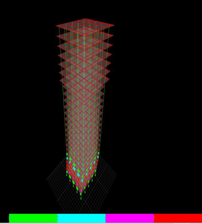
FIGURE3-Hinges
HinglocationcanseelikethisFEMA-356andASCE41-13. varioussoftwarefeatureslikestrengthdrop,displacement control, p-delta effect, staged construction, and link assignmentsareavailableforuseinstaticpushoveranalysis.
PushoverAnalysisFortheprocedureofPushoveranalysis, the required codes are taken from Federal Emergency ManagementAgency(FEMA)andAppliedTechnicalCouncil (ATC) are the two agencies which provide guidelines formulated for the Non-linear Static Analysis or Pushover Analysis under seismic rehabilitation that included documentsFEMA-356,FEMA-273andATC-40
1.2 Objective
Ascivilengineers,ourresponsibilityistodesignstructures thatcanwithstandearthquakesinvariouszonesandprotect people'slives.
Studythedifferenttypesofstructuralirregularities.
Compare structural parameters like storey shear and storeydisplacementinR.C.C.buildings.
Analyzeverticalirregularitiesinstructures.
CompareanalysisresultsofstructuresinseismiczonesIII, IV,andVusingETABSsoftware.
1.3 Aim of Study
Determinetheextent ofpossiblechangesin theseismic behaviorofRCbuildingmodels.
Introduce a symmetrical bare frame building model in differentzonesusingPushoveranalysis.
AssesstheimpactofseismiczonefactorsinzonesIII,IV, andVonthebuilding'sseismicperformance.
3. MODELING
1.Capacity:Thisistheultimatestrengthofastructural component,notconsideringthereductionfactorusedin design.Itreferstothestrengthattheyieldpointonthe capacitycurveandincludesstrainhardeningeffectsfor deformationcontrol.
2.CapacityCurve:Agraphplottingbaseshearagainst roofdisplacement,alsoknownaspushoveranalysis.
3.CapacitySpectrum:Amethodusinggraphstoshow howabuildingmighthandleanearthquake,comparing buildingstrengthtopotentialearthquakeshaking.The "performance point" is where these lines intersect, indicating potential building movement during an earthquake.
4. Demand: Instead of using forces, we estimate how much a building might bend or move during an earthquake,shownina"demandspectrum"graphthat changesovertime.

FIGURE-PUSHOVERFORCE/DISPLACEMENTGRAPH
International Research Journal of Engineering and Technology (IRJET) e-ISSN: 2395-0056
Volume: 11 Issue: 07 | July 2024 www.irjet.net p-ISSN: 2395-0072
5.PerformancePoint:Theintersectionofthecapacity spectrumanddemandspectrumgraphs,indicatinghow wellabuildingdesignhandlesforces.
6. Building Performance Level: The combined performance of structural and non-structural components, described using different performance levelsthroughpushoveranalysis.
7. Operational Level (OP): The building sustains no permanent damage, retaining original strength and stiffness.Majorcracksmayappearinpartitionwallsand ceilings.
8. Immediate Occupancy Level (IM): The building sustains no drift, retaining original strength and stiffness.Minorcracksmayappearinpartitionwallsand structural elements, and elevators and fire protection areoperable.
9.LifeSafety Level (LS):Thebuilding retains residual strength and stiffness, with gravity load-bearing elements functioning. Some drift and damage to partition walls and non-structural elements are observed,buthazardsaremitigated.
10.Collapse Prevention Level (CP): The building has weakenedstrengthandrigiditybutretainsload-bearing capacity.Itmayexperiencesignificantpermanenttilting, collapse of non-essential walls, and damage to nonsupportingparts.
11. Plastic Hinge: The location where inelastic action occursinastructuralmember.
12.FormationofPlasticHinge:Plastichingeslikelyform neartheendsofbeamsandcolumnswheremaximum moments occur during an earthquake, requiring ductilityatthesesections.
3.1 MODEL
Thisstudyfocusesontheearthquakeanalysisofhighrisebuildings.ThespecificationsarebasedonIS18932016 part 1 and IS 13920. Various column and beam sizes were analyzed using ETABS to select the most economicalsections.LoadingdetailsweretakenfromIS 1893-2016part1,IS1893part2,andIS875.Material properties were chosen according to IS 456-2000. Seismicfactorswereselectedbasedonthelocation,type ofstructure,andsoiltypeasspecifiedinIS1893-2016
Make2typeofstorymodel.Firstoneis20story,25 storyand30story.


FUGURE5-beamcolunmproperty
Inthisreasurchweusematerialandsectionsizeasbilove. Theframealimentuseinthemodal areshownasbelowe. Totaltwotypeofcolumnandtwotypeofbeamareuse.
Name Material Shape
C-350x350mm M25 Concrete Rectangular
C-450x450mm M25 Concrete Rectangular
B-230X450mm M25 Concrete Rectangular
B-230X600mm M25 Concrete Rectangular
S-150mm M25 Mambrane


4. RESULTS
Throughthispushoveranalysiswecanunderstandthe bihavierofstructure,andwhichjunctionisfirstcolleps duringtheearthquakewecanunderstand.
Aswecanseeinfigure9,wecanseesomecolourinthis image and this colouers inform that which junction is criticalduringearthquake.
displacement
Themaximumdisplacementofeachstoryduetoearthquake inYdirectionforvariousseismiczonesofIndiahavebeen plottedasabove.Theobservationfromthegraphsleadsto theresultsthatthepatternofthedisplacementforeachzone andforeachstructureremainsame.Theonlychangeisin the value of maximum displacement in different seismic zones. The displacement in irregular buildings is much higher than regularandverticallyirregular buildings.The least displacement has been observed in the regular building.
International Research Journal of Engineering and Technology (IRJET) e-ISSN: 2395-0056
Volume: 11 Issue: 07 | July 2024 www.irjet.net p-ISSN: 2395-0072

FIGURE9-Hinges
Hingies created in model after pushover analysis complitedthisimageshowsthepointatwithpoint collepse.
11-Storyshear

12-Hingies
FIGURE10-Storydisplacement
Themaximumdisplacementofeachstoryduetoearthquake inYdirectionforvariousseismiczonesofIndiahavebeen plotted as above. The observation from the graphsleadsto theresultsthatthepatternofthedisplacementforeachzone andforeachstructureremainsame.Theonlychangeisin the value of maximum displacement in different seismic zones. The displacement in irregular buildings is much higher than regularandverticallyirregular buildings.The least displacement has been observed in the regular building.
5. CONCLUSIONS
Inverticallyirregularstructures,bothdisplacement anddriftvaluesaresignificantlyhighercomparedto regularstructuresduringbothEQ-XandEQ-Y.
Pushoveranalysisindicatesthatmosthingesform atthebasementlevelandatpointswherethereare sudden changes in the plan. Irregular structures have the most hinges, followed by vertically irregularstructures,andthenregularstructures.
Collapse hinges are only found in irregular and verticallyirregularstructures,withnoneobserved inregularstructures.
REFERENCES
[1] Kangle, S. R., and D. S. Yerudkar. "Response Spectrum Analysis for Regular Multistory Structure in Seismic
International Research Journal of Engineering and Technology (IRJET) e-ISSN: 2395-0056
Volume: 11 Issue: 07 | July 2024 www.irjet.net
ZoneIII." International Journal of Engineering Research & Technology (IJERT), ISSN (2020):2278-0181.
[2] Rathod, Kaushal Vijay, and Sumit Gupta. "A nonlinear time history analysis of ten storey RCC building." InternationalResearchJournalofEngineering and Technology 7(2020):7153-7160.
[3] Mahmoud,Sayed,MagdyGenidy,andHeshamTahoon. "Time-history analysis of reinforced concrete frame buildingswithsoftstoreys." Arabian Journal for Science and Engineering 42(2017):1201-1217.
[4] Firoj,M.,andS.K.Singh."Responsespectrumanalysis for irregular multi-storey structure in seismic zone V." 16th Symposium on Earthquake Engineering, IIT Roorkee, India.2018.
[5] Dadawala, Saunil, and N. R. Chandak. "Response spectrum analysis of multi storied buildings: A review." 2018 Advances in Science and Engineering Technology International Conferences (ASET). IEEE, 2018.
[6] Keerthigowda, B. S., and Syed Tajoddeen. "Seismic analysis of multistorey building with floating columns." IEEE Trans. Power System 19.1(2014):356365.
Codes:
ATC-40. “Seismic evaluation and retrofit of concrete buildings.” Volume 1 and 2. Applied Technology Council,California,1996.
FEMA-273. “NEHRP guidelines for the seismic rehabilitation of buildings.” Federal Emergency ManagementAgency,WashingtonDC,1997.
FEMA-356. “Prestandard and commentary for the seismic rehabilitation of buildings.” Federal Emergency Management Agency, Washington DC, 2000.
IS:1893(Part1)2002-Indianstandard-“Criteriafor earthquakeresistantdesignofstructures”,Bureauof IndianStandards,NewDelhi.