
International Research Journal of Engineering and Technology (IRJET) e-ISSN:2395-0056
Volume: 11 Issue: 07 | July 2024 www.irjet.net p-ISSN:2395-0072
International Research Journal of Engineering and Technology (IRJET) e-ISSN:2395-0056
Volume: 11 Issue: 07 | July 2024 www.irjet.net p-ISSN:2395-0072
Ghanshyam L. Jodhani1, Kishan Pala2
1M. Tech Student, L.J. University, Ahmedabad
2Kishan Jayswal, Assistance Professor, Civil Engineering Department, L.J. University, Ahmedabad, India.
Abstract - With advancements in urban design software and significant improvements in the fields of engineering and technology, high-rise structures are increasingly common. As the height of buildings increases, their response to seismic and wind loads also intensifies. According to Indian standard codes, the displacements and forces experienced by a structure are directly proportional to its height. Ongoing research focuses on mitigating these responses during extreme horizontal loading due to seismic activity and wind forces. One effective solution involves the use of passive control devices, such as various types of dampers, to manage andreduce the impact ofthese loads.
Key Words: Fluid viscous dampers, Displacement, Storey Drift and Storey shear, ETABS
1. INTRODUCTION
1.1 General
Which different kind of load is acting on RC building?
Various types of loads act on reinforced concrete (RC) buildings. In India, the major loads considered are dead load, live load, seismic load, and wind load (for buildings taller than 10 meters, as per IS 875 Part 3). However, accordingtoIS456Table18,whenconsideringtheeffectof earthquakes, the wind load is substituted by the earthquake load in the specified load combinations. This substitution reflects the prioritization of seismic effects over wind effects in structural design under earthquake conditions.
Dead Load:
Dead load is mainly caused by the individual weight ofthestructureandthecompletionofthestructure.Dead loadsarecarriedoutonlyintheverticaldirection.Wecan only assume that no tipping occurred due to static properties.
Live Load:
Live load in a building is due to occupants, furniture, vehicles, and other movable objects. The value of live load variesdependingonthetypeof building,asspecifiedin IS 875 Part 2. This standard provides guidelines for determining the appropriate live load values for different
building categories to ensure safety and structural integrity.
Earthquake Load (Seismic load):
Seismic load is the horizontal force exerted on a building due to ground shaking during an earthquake. Theseloadsareclassifiedas "dynamicloads." Unlikeother types of loads, which generally act slowly on a structure, seismicloadsactrapidlyandcausethestructuretovibrate intensely.
What is earthquake resistant building?
An earthquake-resistant building is designed to withstand various levels of seismic activity without significant damage. In a weak earthquake, no damage is allowed in structural members, and no major damage is permitted in non-structural members. During a moderate or moderately strong earthquake, some structural damage is allowed, but it should be repairable, and no major damage should occur. In a strong earthquake, major damage is allowed, but the structure must not collapse. This type of design ensures the building maintains its integrity and provides safety for occupants during and afteranearthquake.
What is damper?
“Dampers are energy dissipation system”.
Dampers are devices used to dissipate or absorb vibrations resulting from an earthquake, thereby increasing the damping and stiffness of a structure. These devices help to control and reduce the seismic response, enhancing the overall stability and safety of the building duringseismicevents.
Different type of damper majorly used in building.
1] FluidViscousDampers(FVD)
2] ViscoelasticDampers
3] FrictionDampers
4] TunedMassDamper(TMD)
5] YieldingDampers
6] MagneticDamper
International Research Journal of Engineering and Technology (IRJET) e-ISSN:2395-0056
Volume: 11 Issue: 07 | July 2024 www.irjet.net p-ISSN:2395-0072
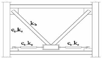
1.2 Fluid viscous dampers:
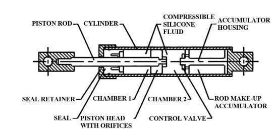
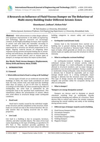
Figure 1: Schematic Detailing of Fluid Viscous Damper Components
In fluid viscous dampers, seismic energy is absorbedbyasilicon-basedfluidpassingthroughapistoncylinder arrangement. These dampers are commonly used in buildings located in higher earthquake zones. They effectively operate within a temperature range of 40°C to 70°C, significantly reducing vibrations caused by earthquakes and enhancing the building's seismic resilience.
Component of Fluid viscous dampers.
1] PistonRod
2] Cylinder
3] SiliconeFluid
4] AccumulatorHousing
5] SealandSealRetainer
6] Chamber-1andChamber-2
7] PistonHeadwithOrifices
8] ControlValve
9] RodMake-upAccumulator
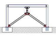
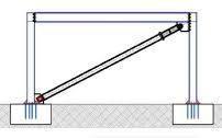
Types of connection of Fluid viscous dampers
Therearethreewaystoconnectdampers,
1] Infloororfoundation
2] Insternpericardialbraces
3] Indiagonalbraces
4: Floor or Foundation
1.3 Terminologies:
Displacement:
"The displacement of a structure is defined as the distancefromtheoriginalpositionofasamplepointonthe structuretoitsfinallocationafterdeformation."
Story Drift:
"The lateral displacement between consecutive floorsisknownasstoreydrift."
"The ratio of storey drift to the floor height is knownasthestoreydriftratio."
Story Shear force:
"The lateral force acting on a storey due to forces suchaswindloadorseismicloadisknownasstoreyshear force."
"A building with less stiffness attracts less storey shear, while a building with more stiffness attracts more storeyshear."
1.4 Objective
The main objective of this study is to check the kind of performance a building can give when designed as per IndianStandards.
TheAnalysisofthebuildingframeiscarriedoutbyusing structural analysis and design software ETABS (version 21).
• ToanalyseStoreydisplacementofbuilding.
• ToanalyseStoreydriftofbuilding.
• ToanalyseStoreyshearofbuilding.
WeuseETABS(version21) toanalysethemodelofan RCCbuilding,consideringvariousparametersforcolumns, beams, and other structural components. Our analysis accounts for different seismic zones and varying types of soil conditions to ensure comprehensive evaluation and designofthestructure'sseismicresilience.
2. NUMERICAL STUDY
Here we consider G+7 and G+9 storey RCC frame buildingforstudy.
International Research Journal of Engineering and Technology (IRJET) e-ISSN:2395-0056
Volume: 11 Issue: 07 | July 2024 www.irjet.net p-ISSN:2395-0072
Followingdifferentcasetobestudied.
1] Buildingwithoutanydampers.
2] Buildingwithfluidviscousdamperatbasecorner
3] Buildingwithfluidviscousdamperatbasemiddle
4] BuildingwithFVDatcornerin1st twostorey
5] buildingwithFVDatmiddlein1st twostorey
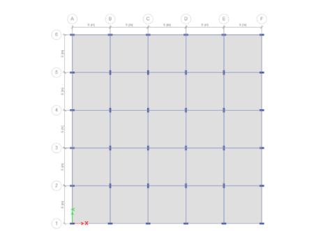
Figure 5: Plan view of building
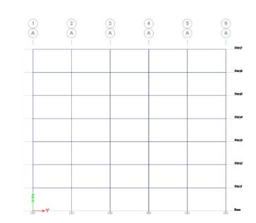
Figure 6: Elevation of building
Table 1: Detail of Building
TypeofBuilding Residencial
PlanDimension 25mx25m
StoreyHeight 3m
NumbersofStorey G+7
Table 2: Material properties
GradeofConcrete M30
DensityofConcrete 25kN/m3
GradeofSteel Fe415
DensityofSteel 76.9729kN/m3
Modulusof elasticityofCon. 27386.13MPa
Modulusof elasticityofSteel 2x10⁵ MPa
Table 3: Section Properties
Table 4: Gravity Load
Self-Weight TakenbyETABS
FloorFinishfor Typical 1.5kN/m2 FloorFinishfor Terrace 2.3kN/m2
Load 5.57kN/m2
Load 2kN/m2
Table 5: Seismic Properties
ImportanceFactor 1 Response ReductionFactor 5
III,IV,V ZoneFactor 0.16,0.24,0.36
SoilType II(Medium)
Table 6: Damper Properties
Comparison of maximum displacement in X and Y direction in all five cases of building which we got from ETABS while analysed model is shown in figure 7 and figure8
International Research Journal of Engineering and Technology (IRJET) e-ISSN:2395-0056
Volume: 11 Issue: 07 | July 2024 www.irjet.net p-ISSN:2395-0072
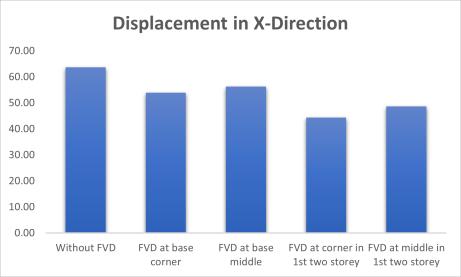
Figure 7: Maximum displacement in X-Direction
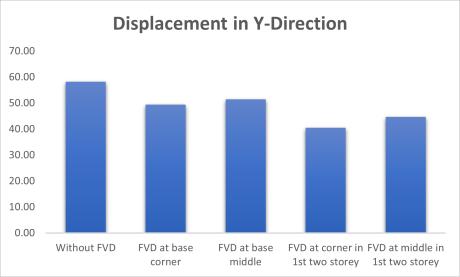
Figure 8: Maximum displacement in Y-Direction
Comparison of maximum storey drift of building is shown infigure9andfigure10.
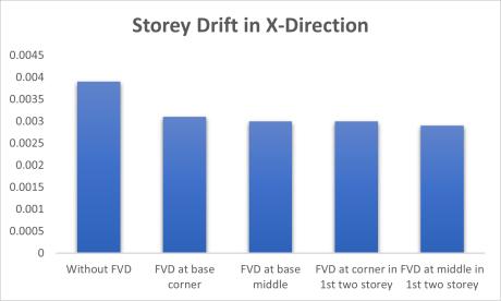
9: Maximum
in X-Direction
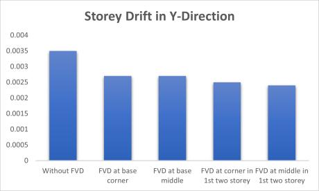
Figure 10: Maximum Storey drift in Y-Direction

Figure 12: Maximum Storey shear in Y-Direction
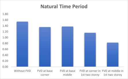
Comparison of maximum Natural Time Period in all five casesofbuildingwhichwegotfromETABSwhileanalysed modelisshowninfigure13.
Fromallabovestudywecanconcludethat,
Displacement of Building without FVD is more than DisplacementofbuildingwithFVD.
Storey drift and storey shear also decrease with InclusionofFluidviscousdampers.
Storey Shear and Storey Drift is more less at storey where dampers are provided. Very next storey to the damper huge deflection noticed in graph of storey shearandstoreydrift.
Decrement is higher when fluid viscous dampers add at corner of building as compared to fluid viscous
dampersatmiddle.
There is no huge difference in result when we change positionofdamperscornertomiddle.
Onlybasedampingand1st twostoreydampinghasno huge difference like building without dampers and buildingwithbasedamping.
Compar lfivecasesofbuildingwhichwegotfromETABSwhile analysed
isonofmaximumstoreyshearinXandYdirection inal modelisshowninfigure11andfigure12.
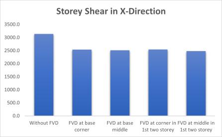
Figure 11: Maximum Storey shear in X-Direction
Time period is decrease with FVD, so natural frequencyofbuildingisincreased.
Time period is stiffness-based property of building so we can decrease it by increase size of column or by addingDampers.
With change of zonefactor thereis nochange in Time periodofbuilding.
International Research Journal of Engineering and Technology (IRJET) e-ISSN:2395-0056 Volume: 11 Issue: 07 | July 2024 www.irjet.net p-ISSN:2395-0072
Milton Fernandes 1, Swane Rodrigues 2, Suraj Sharma3, Smit Raut 4, Mr. Shreeshail Heggond 5, “Comparative Study of Seismic Behavior of High Rise Building with and Without Use of Fluid Viscous Damper Using E-Tabs”, International Journal of Innovationsin Engineering and Science, www.ijies.net, e-ISSN:2456-3463Vol.6,No.5,2021,PP.22-30
Daniel C, Arunraj E, Vincent Sam Jebadurai S, Joel SheltonJ,HemalathaG,“DynamicAnalysisofStructure using Fluid Viscous Damper for Various Seismic Intensities”, International Journal of Innovative Technology and Exploring Engineering (IJITEE) ISSN: 2278-3075,Volume-9Issue-1,November2019
Vibha More, Dr. Vikram Patil, Somanagouda Takkalaki, “Dynamic Analysis of RCC FrameStructures with and Without Viscous Damper Having Different Aspect Ratio”, IJISET - International Journal of Innovative Science, Engineering & Technology, Vol. 6 Issue 10, October 2019 ISSN (Online) 2348 – 7968 | Impact Factor(2019)–6.248
N. Priyanka, Dr. J. Thivya, J. Vijayaraghavan, “SEISMIC STUDY OF MULTI-STOREY STRUCTURE WITH FLUID VISCOUS DAMPERS USING ETABS”, International Research Journal of Engineering and Technology (IRJET),Volume:06Issue:04|Apr2019.
Madhuri S L, Lakshmi P S, “Seismic Performance Evaluation of Fluid viscous Damper”, International Journal of Advances in Engineering and Management (IJAEM),Volume4,Issue7July2022.
B Rakesh, Shiva Shankar K M and Navya K S, “Seismic AnalysisofTallStructuresbyusingDampersinETABS”, International Journal of Innovative Science and Research Technology ISSN No: -2456-2165, Volume 7, Issue4,April–2022
IS 1893 (Part 1): Indian Standard Criteria for Earthquake Resistant Design of Structures: General Provisions and Buildings. Bureau of Indian Standards; 2016.
IS 875 Part 2. Indian Standard Code of Practice for Design Loads (Other than Earthquake) for Building and Structures: Imposed Loads. Bureau of Indian Standards,NewDelhi,India;1987.