
International Research Journal of Engineering and Technology (IRJET) e-ISSN: 2395-0056
Volume: 11 Issue: 07 | July 2024 www.irjet.net p-ISSN: 2395-0072

International Research Journal of Engineering and Technology (IRJET) e-ISSN: 2395-0056
Volume: 11 Issue: 07 | July 2024 www.irjet.net p-ISSN: 2395-0072
Siddhesh Done1 , Ajay Desai2 , Aniket Patil3, Aditya Bhagwat4
1234 UG Student, Department of Mechanical Engineering, K.I.T.’s College of Engineering, Kolhapur, Maharashtra, India.
Abstract - Thegoalofthisprojectreportistostudythe designanddevelopmentofaself-balancingbicyclewiththe goal of achieving static stability using advanced control systemsandsensorintegration.Themajorgoalwastouse self-balancingtechnologiestobuildabicyclethatcansustain its upright posture on its own without assistance from an outsidesource.Theprojectincludedsoftwaredevelopment, electrical engineering, and mechanical design in an interdisciplinary manner. Among the essential parts were accelerometers and gyroscopes for real-time motion and orientationdata,Weusedastrictapproachthroughoutthe entireproject,beginningwiththecreationofatheoretical framework and a thorough assessment of the literature. Next, we carefully selected each component, taking into account factors like cost-effectiveness, correctness, and dependability. Assembling the mechanical components, integrating the electronic components, and creating the required software algorithms were all part of the implementation phase. The system's robustness and performancewereconfirmedthroughextensivetestingand validation. The project's goals were met when the results showed that the self-balancing bicycle could successfully maintainequilibriuminavarietyofsituations.Inadditionto confirming that self-balancing systems in bicycles are feasible,thisexperimentofferedinsightfulinformationabout the difficulties and possible solutions for further advancement. The accomplishment of this project successfullyestablishesasolidbasisforadditionalstudyand applications in robotics and personal transportation. Conclusively, the self-balancing bicycle project signifies a noteworthyprogressionincomprehendingandutilizingselfbalancing mechanics, underscoring the possibility of inventive approaches to augment mobility and stability throughoutseveralfields.
Keywords-Interdisciplinary Approach,Self Balancing,Strong Foundation, Static Stability.
Concernovertheincreasingnumberoftraffic-relateddeaths andinjuriesisgrowingglobally.Themajorityoftwo-wheeler riders die at the scene of traffic accidents, where they are involved.Two-wheeledVehiclesareamorepopularformof transportation since they are affordable, practical, and efficient with time. Research indicates that the number of accidents has been rising over time, with the main factor contributing to this trend being the intrinsic instability of
two-wheeledvehicles.Inaddition,theinstabilityofthetwo wheels in both stable and dynamic settings make it challengingfor individualswithdisabilitiesto operatethe vehicle.
PeopleinIndiausetwo-wheeledvehicleswithfrontandrear wheels for transportation. If the bike flips over sideways, therecanbefeweraccidents.
Globally,thereisgrowingworryovertheescalatingtollof traffic-related fatalities and injuries. Most two-wheeler riders die instantly in traffic crashes, if they are involved. Two-wheeledcarsduetotheiraffordability,timeliness,and practicality, are growing in popularity as means of transportation.Studiesrevealthatthenumberofaccidents hasbeenrisingovertime,withthefundamentalinstabilityof two-wheeled vehicles being the main contributor. Furthermore,itischallengingforthosewithdisabilitiesto operate the vehicle due to two-wheeler instability in both stableanddynamicsettings.
1. To identify bicycle instability in both static and dynamicconditions.
2. Tokeepthebikestableandpreventsidewaysfalls.
1. The tilt and acceleration of a bicycle's motion are detectedusinggyroandaccelerometersensors.
2. Gyroscopicconceptisusedtostabilizethebicycle.
Sidharth R, V K Pranav, Nitheesh Kumar G, Pramod Sreedharan, and Gayathri G
This work explores the notion of stabilizing the bicycle throughtheapplicationofgyroscopicprecessiontheory.To verifythatthechosenmaterialisadequateandcapableof supportingtheexpectedloads,astatically-analysedbicycle frameisused.DuringFurthermore,astudyisconductedon thebicycle'smotionatdifferentflywheelspeeds.Theresult demonstrates that when the bicycle is stationary, the flywheelRPMgrowsalongwiththecycle'stotaltoppletime, andthatwhenthebicycleismoving,anidealflywheelspeed isnecessary.Becauseofthebuilt-inmodel'slimitedflywheel
International Research Journal of Engineering and Technology (IRJET) e-ISSN: 2395-0056
Volume: 11 Issue: 07 | July 2024 www.irjet.net
capacity, higher RPM motors are required to create an uprightbicycle.Itcantakeabicyclealongtimetotoppleif highRPMmotorsaren'tused.
Mehmet Ali Eroğlu, Mehmet Kürşat Yalçın
A self-balancing bicycle with support and rising up mechanismsisbuiltinthisstudyusingaCMGwithasingleaxis gimbal. To ascertain the responses of the system, structuralevaluationsbasedonfiniteelementmodelingare conducted.Theresearchreachedthefollowingconclusions: Rising flywheel spin and gimbal angular rate result in an increase in the gyroscopic moment. Gyroscopic moment demandincreaseswithadditionalload.Thebicycle'sdriving mechanism is ineffective during a gyroscopic moment regardless of which wheel is in front or back. There is no relationshipbetweendrivingtorqueandgimbaltorque. It is necessary to select rough as the wheel-road contact type.Toslip,fly,turn,andbounce,makeothercontacts.An activeself-balancingrequirestheuseofacontrolstrategy.
Yadhu Krishnan, Ishaan Rahul Saxena
Using the gyroscopic effect, a two-wheeled bike that can balance itself was created. The prototype model could countertorque0.28N-cmforamaximumtiltof30degrees andself-balanceatamaximumspeedof118rpmalongthe vertices.Theprimarygoaloftheprojectwastominimizethe amountofspacetakenup,thetotalweightoftheassembly, andthedistancetotheCenterofGravityfromtheground. Thiswasaccomplishedinpartbyusingaverticalmomentum flywheel and layering the components to create a smaller two-wheelermodel.Afterobservingandanalyzingtheactual andtheoreticaltorqueandneededrotationalspeedvalues,it wasconcludedthattheexperimentalvaluedifferedfromthe theoreticalvaluebytheleastamount.
Akash C, Devapraseeth, Jills Babu, Mohammed Ryan, Mr. G Thilak
This project describes how to power a bicycle for long distanceridingwhileutilizingallavailableenergysourcesas efficientlyasfeasible.Themethodsforincludingrideraidto promotesafetyandconvenienceofridingarealsocoveredin this research. We've got established this idea with the intentionofprovidingadependableandreasonablypriced means of transportation, particularly for the underprivileged. Two distinct technologies that have previously been used in conjunction have been skillfully mergedtoprovidea novelandreasonablypricedmodeof transportation. Our concern for the causes and effects of environmentaldegradationledustoundertakethiseffortas well.
Inself-balancingmechanics,sensorsandcontrolsystemsare usedtokeepanobjectstableinanuprightposition likea bicycle without the need for outside assistance. These are themainideasthatunderpinself-balancingmechanics.
1.FundamentalIdeas:
p-ISSN: 2395-0072
AngularMomentum:Arotatingobject'srotationalmotionis quantifiedbyitsangularmomentum.Therotationalspeed andmomentofinertiaoftheitemdeterminethemagnitude oftheangularmomentumvector,whichpointsalongtheaxis ofrotation.
Gyroscopic Effect: A gyroscope has a tendency to resist changesinitsaxisofrotationwhileitisrotating.Gyroscopic stabilityisthenamegiventothisresistance.Thegyroscope ismorestablethequickeritrotates.
2.Feedbacksystemsandsensors:
Accelerometers and Gyroscopes: The angular velocity is measuredbythesesensors.
Theconceptsofangularmomentumandgyroscopic effect underpintheoperationofgyroscopicbalance.Thefollowing explainshowitfunctions:
1. Spinning Gyroscope: A gyroscopeis made up of a rotor,whichisadiskorwheel,placedsuchthatit mayrotatequicklyarounditsaxis.Rotatingobjects generateangularmomentum.
2. Resistance to Tilt: The spinning gyroscope resists tiltinganddoesnotsimplytiltinthedirectionofthe appliedforcewhenanexternalforcetriestotiltits axis. Instead, it undergoes a response known as precessionasaresultoftheconservationofangular momentum. The gyroscope's axis moves perpendiculartothedirectionoftheappliedforce duetoprecession.
3. Precession: The relationship between the rate of precessionandtheangular
8. CALCULATIONS FOR SYSTEM DESIGN
Parameters
MassofBicycle 12 Kg
Massofflywheel 3.5 Kg
Additional weight on Bicycle 15 Kg
Height of CG of BicyclefromGround 0.5 Meter
Table -1: componentspecification
m=massofthebicycle=12kg
m=massoftheflywheel=3.5kg
Additionalweightonbicycle=15kg
For Tilt angle 15 degree, Torque=Mghsin(Ѳ)=30.5*9.81*0.5*sin(15) (maximumtiltangleisconsidered15degrees)
Torque=38.72Nm
International Research Journal of Engineering and Technology (IRJET) e-ISSN: 2395-0056
Volume: 11 Issue: 07 | July 2024 www.irjet.net p-ISSN: 2395-0072
To counteract the deflection in the centre of mass of the bodyweneedtoequalizethecentrifugalforceproducedby theflywheeltopotentialenergyreducedbythedeflection. Angularvelocityrequiredtoliftthebicycleupright
V^2=u^2+2*g*h
Asinitialvelocityis0, Therefore u=0
V^2=2*9.81*0.5
Therefore,
V=3.14m/s
Wp=V/r=3.13/0.5=6.26rad/s
I=mr^2/2=3.5*0.1^2/2
I=0.0175kg.m^2
T=I*w*Wp38.72=0.0175*w*6.26
w=353.44rad/s
N=353.44*60/2*3.14
N=3377rpm
Motorofrpm3500isrequired.
For Tilt angle 10 degree,
Torque=Mghsin(Ѳ)=30.5*9.81*0.5*sin(10)
Torque=25.97Nm
To counteract the deflection in the centre of mass of the bodyweneedtoequalizethecentrifugalforceproducedby theflywheeltopotentialenergyreducedbythedeflection.
Angularvelocityrequiredtoliftthebicycleupright
V^2=u^2+2*g*h
Asinitialvelocityis0,therefore u=0
V^2=2*9.81*0.5
Therefore,
V=3.14m/s
Wp=V/r=3.13/0.5=6.26rad/s
I=mr^2/2=3.5*0.1^2/2
I=0.0175kg.m^2
T=I*w*Wp25.97=0.0175*w*6.26
w=237.06rad/s
N=353.44*60/2*3.14
N=2263rpm
Motorofrpm2300isrequired.
For Tilt angle 5 degree,
Torque=Mghsin(Ѳ)=30.5*9.81*0.5*sin(5)
Torque=13.03Nm
To counteract the deflection in the centre of mass of the bodyweneedtoequalizethecentrifugalforceproducedby theflywheeltopotentialenergyreducedbythedeflection. Angularvelocityrequiredtoliftthebicycleupright
V^2=u^2+2*g*h
Asinitialvelocityis0, Therefore,
u=0V^2=2*9.81*0.5
Therefore,
V=3.14m/s
Wp=V/r=3.13/0.5=6.26rad/s
I=mr^2/2=3.5*0.1^2/2
I=0.0175kg.m^2
T=I*w*Wp13.03=0.0175*w*6.26
w=118.94rad/s
N=118.94*60/2*3.14
N=1135rpm
Motorofrpm1200isrequired.
For 0 degrees As sin(0) = 0, atlastwegetrequiredRPM=0, Butinordertoreducemotortorqueweassume, N=500rpm
For,tiltangle=0degree
Calculation for motor selection,
T=I*α
Tofindα,
α=W1-W2/T=1400-500/5=180
Now,
T=0.0175*180
T=3.15Nm
So the motor of Torque=3.15 Nm and N=3500 rpm is selected.
TiltAngle(Degree) Motorspeed(RPM) 0 500 5 1200 10 2300 15 3500
9.COMPONENTS OF SYSTEM
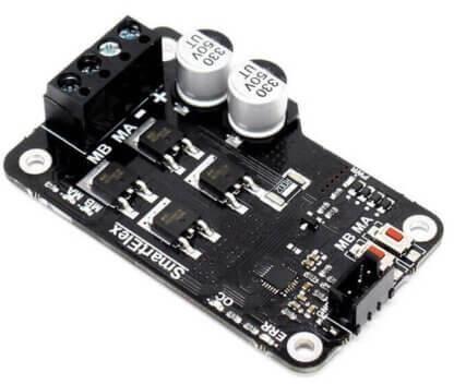
1.SmartElex15SDCMotorDriver15A(30APeak):
•SupplyVoltage:6.8-30VDC.
•ContinuousCurrent:15Amp.
•MaxPeakcurrent:30Amp(For10Seconds).
•PWMFrequency:20KHz.
•OnebrushedDCmotorBidirectionalcontrol.
2.SpoinkkyMPU-6050Module3AxisGyroscope
• Features three-axis gyroscope and three-axis accelerometer
• Communication modes: Standard iic communications protocol
•Chipbuilt-in16bitadconverterwith16-bitdataoutput
•Gyroscoperange:25050010002000°/s.
International Research Journal of Engineering and Technology (IRJET) e-ISSN: 2395-0056
Volume: 11 Issue: 07 | July 2024 www.irjet.net p-ISSN: 2395-0072
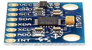
Figure-2: Gyrosensor.
3.RobodoSEN4IRInfraredObstacleAvoidanceSensor,E18D80NK:
•Effectivedistance:Adjustablefrom3-80cm
•Electricalcharacteristicsu:5vdci:The100ma
•Angle:Morethan15degree
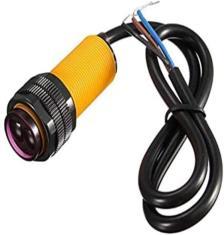
Figure-3: IRProximitysensor
4.DisplayUnit:
•16x2CharacterLCDdisplaymodule.

Figure-4: DisplayUnit
5.SerialModule:
•IICI2CSerialInterfaceBoardModule
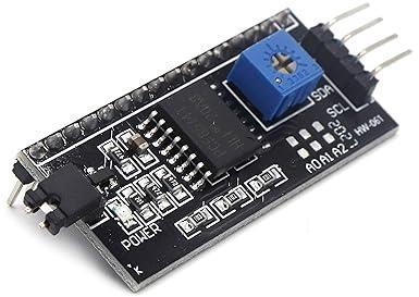
Figure-5: SerialModule
6.Battery:
•Capacity:7.5Amp
•Voltage:12v

Figure-6: Battery.
7.DCMotor:
•Speed:5000RPM
•Voltage:12V,HP:60Watts
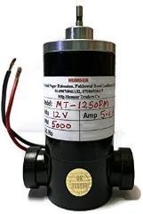
Figure-7: DCMotor.
10. SYSTEM CODE
#include<Wire.h> #include<LiquidCrystal_I2C.h> #include<MPU6050.h>; //Pin9isconnectedtoOCR1A MPU6050mpu; #definesensor2 #definedir8 #definepwmPin9
FloatXvalue; intrpm=0; inti=0; unsignedlongmillisBefore; volatileintobjects; LiquidCrystal_i2Clcd(0x27,16,2)
Voidsetup()
{ Serialbegin(9600); lcdbegin(); lcdbacklight(); lcdprint(“SELF-BALANCING”); lcdsetCursor(0,1); lcdprint(“TWO-WHEELER”); delay(2000); lcdclear(); attachInterrupt(digitalPintoInterrupt(2),count,FALLING); delay(1000); pinMode(2,INPUT); while(!mpu_begin(MPU6050_SCALE_2000DPS, MPU6050_RANGE_2G))
{ Serial_println(“ Could not find a valid MPU6050 sensor, checkwiring!”); delay(500); } checkSettings(); pinMode(numPin,OUTPUT); pinMode(dir,OUTPUT); digitalWrite(dir,HIGH); //Stopthetimer TCCR1A=0;
International Research Journal of Engineering and Technology (IRJET) e-ISSN: 2395-0056
Volume: 11 Issue: 07 | July 2024 www.irjet.net p-ISSN: 2395-0072
TCCR1B=0; TCNT1=0;
//SetFastPWMmodewithICR1asTOP TCCR1A=(1<<WGM11); TCCR1B|=(1<<WGM12)|(1<<WGM13);
//SetICR1todefinethePWMfrequency //ICR1=(16,000,000/(32,000*1))-1=499 ICR1=499;
//Setthedutycycleto50%(OCR1A=ICR1/2) OCR1A=249;
//EnableoutputcomparematchAmode TCCR1A|=(1<<COM1A1); } voidchechSettings(); { Serial_println();
Serial_print(“*SleepMode: “); Serial_println(mpu_getSleepEnabled()?”Enabled”: “Disabled”);
Serial_print(“*ClockSource: “); Switch(mpu_getClockSource()) { caseMPU6050_CLOCK_KEEP_RESET. Serial_println(“Stops theclockandkeepsthetiminggeneratorinreset”);break; case MPU6050_CLOCK_EXTERNAL_19MHZ: Serial_println(“PLL with external 19.2MHz reference”);break; case MPU6050_CLOCK_EXTERNAL_32KHZ : Serial_print;n(“PLLwith external 32.768kHz reference”): break;
case MPU6050_CLOCK_PLL_ZGYRO: Serial_println(“PLL withZaxisgyroscopereference”);break; caseMPU6050_CLOCK_PLL_YGYRO: Serial_println(“pllwith yaxisgyroscopereference”);break; case MPU6050_CLOCK_PLL_XGYRO: Serial_println(“PLL withXaxisgyroscopereference”);break; case MPU6050_CLOCK_INTERNAL_8MHZ: Serial println(“Internal8MHzoscillator”);break; }
Serial_PRINT(“*Accelerometer.”); Switch(mpu_getRange())
{ Case MPU6050 RANGE_16G: Serial_println(“+/-16g”); break;
CaseMPU6050_RANGR_8G:Serialprintln(“+/-8g”);break; CaseMPU6050_RANGE_4GSerial_println(“+/-4g”);break; CaseMPU6050_RANGE_2GSerial_println(“+/-2g”);break; } } Voidloop()
{ VectorrawAccel=mpu_readRawAccel(); VectornormAccel=mpu_readNormalizeAccel(); If(millis()-millisBefore>1000)
{ Rpm=(objects/4.0)*60; Objects=0; millisBefore=millis(); } Delay(100); //Serial_print(“Speed:”); //Serial_println(rpm); Lcd_setCursor(0,0); Lcd_print(rpm); Lcd_print(“ ”); Lcd_setCursor(0,1); Lcd_print(normAccel_XAxis-0.1);
If((normalAccel_Xaxis-0.1)>=2 or (normalAccel_XAxis0.1)<=-2) {i=360; }
Else if((normalAccel_XAxis-0.1)>=1.5 or (normalAccel_XAxis-0.1)<=-1.5) {i=360; }
Elseif((normalAccel_XAxis-0.1)>=1or(normalAccel_XAxis0.1)<=-1) {i=240; }
Else if((normalAccel_XAxis-0.1)>=0.5 or (normalAccel_XAxis-0.1)<=-0.5) {i=140; }
Elseif((normalAccel_XAxis-0.1)==0) {i=50; } OCR1A=I; } Voidcount() {objects++; }
International Research Journal of Engineering and Technology (IRJET) e-ISSN: 2395-0056
Volume: 11 Issue: 07 | July 2024 www.irjet.net p-ISSN: 2395-0072
11.DESIGN AND ASSEMBLY OF MECHANICAL SYSTEM
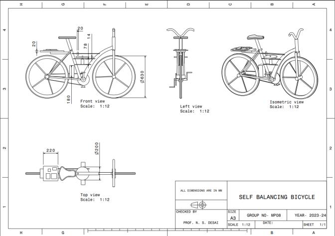
: AssemblyOfMechanicalSystem-2
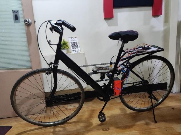
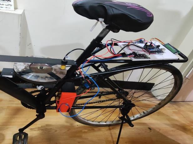
12 .DESIGN AND ASSEMBLY ELECTRONICS SYSTEM
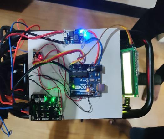
AssemblyOfElectronicsSystem
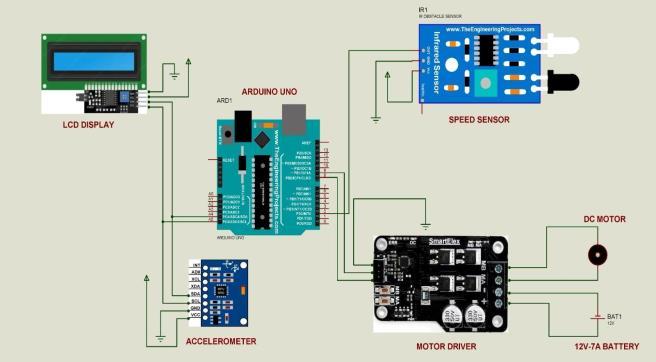
Circuit Of Electronic System
13.CONCLUSION AND FUTURE ENHANCEMENTS:
The self-balancing bicycle project has reached a major milestone with its completion. a turning point in the research and use of sophisticated control systems and sensor integration. By carefully planning, creating, and testing our product, we have effectively produced a prototype that effectively illustrates the fundamentals of self-balancingmechanicsinanactualsituation.
KeyAchievements:
Innovative Design: To achieve dynamic stability, we integrated essential parts including gyroscopes, accelerometers,microcontrollers,andmotorsintoasturdy mechanical and electronic framework. AdvancedControlSystems:Bycontinuouslymodifyingthe bicycle'sorientationinresponsetoreal-timesensordata,the Proportional-Integral-Derivative (PID) control system has been shown to be effective in maintaining balance. SuccessfulIntegrationofSensors:Accurateandresponsive data were obtained by the use of accelerometers and gyroscopes, enabling precise adjustments to offset imbalances.
International Research Journal of Engineering and Technology (IRJET) e-ISSN: 2395-0056
Volume: 11 Issue: 07 | July 2024 www.irjet.net p-ISSN: 2395-0072
EffectivePrototypingandTesting:Wewereabletoimprove the self-balancing bicycle's overall performance and dependabilitybyrefiningthesystemandaddressingissues throughouriterativeapproachtoprototypingandtesting.
ProjectOutcomes:
Deepened Understanding: The project improved our comprehension of the intricate relationships between ssoftware algorithms, electrical control, and mechanical design that are present in self-balancing systems. Application in Practice: By effectively demonstrating theoreticalideasinareal-worldsetting,thedevelopmentof a self-balancing bicycle helps to close the knowledge gap betweenacademiaandpracticalapplication.
BasisforFutureWork:
The knowledge acquired and the technologies created throughout this research provide a strong basis for subsequentdevelopments.Potentialresearchtopicsinclude boosting the system's resilience against different disruptions, investigating alternative sensor technologies, andoptimizingtheeffectivenessofthecontrolalgorithms.
ChallengesandLessonsLearned: ComplexityofIntegration:Combiningsoftware,electronics, and mechanical components presented many difficulties, highlighting the necessity of interdisciplinary cooperation and extensive testing. SensitivitytoDisturbances:Thenecessityofadaptivecontrol strategies was brought to light by ensuring the system's resiliencetooutsidedisturbancessuchuneventerrainand abrupt movements. Iterative Improvement: The iterative character of the developmentprocesshighlightedtheimportanceofongoing testing and improvement, enabling us to swiftly resolve problems and make small but significant system improvements.
FutureDirections:
Future work may concentrate on miniaturizing the componentsforamorecompactdesignandenhancingthe control algorithms for quicker reaction times. Improved User Interface: By creating a user-friendly interface, usability and accessibility of the system parameters monitoring and altering might be increased. Product development and commercialization may be facilitated by investigating the self-balancing bicycle's commercial viability, including prospective market applications and user demographics. To sum up, the self-balancing bicycle project has been a fruitful and educational undertaking. The practical application of a self-balancing mechanism not only shows that these systems are feasible, but it also creates new opportunities for robotics and personal transportation innovations. We are enthusiastic about the possible developmentsandusesthatthisfoundationalworkmaylead tointhefuture.
[1] D. Kornack and P. Rakic, “Cell Proliferation without NeurogenesisinAdultPrimateNeocortex,”Science,vol. 294, Dec. 2001, pp. 2127-2130, doi:10.1126/science.1065467.
[2] M.Young,TheTechnicalWriter’sHandbook.MillValley, CA:UniversityScience,1989.
[3] R. Nicole, “Title of paper with only first word capitalized,”J.NameStand.Abbrev.,inpress.
[4] K.Elissa,“Titleofpaperifknown,”unpublished.


SiddheshSunilDone Student
K.I.T’s College Of Engineering, Kolhapur.
AniketBhikajiPatil Student
K.I.T’s College Of Engineering, Kolhapur.
AjayRamchandraDesai Student
K.I.T’s College Of Engineering, Kolhapur.
AdityaRavindraBhagwat Student
K.I.T’s College Of Engineering, Kolhapur.