
International Research Journal of Engineering and Technology (IRJET) e-ISSN:2395-0056
Volume: 11 Issue: 07 | July 2024 www.irjet.net p-ISSN:2395-0072

International Research Journal of Engineering and Technology (IRJET) e-ISSN:2395-0056
Volume: 11 Issue: 07 | July 2024 www.irjet.net p-ISSN:2395-0072
Md. Sharuf Ali1 , Mr. Mohammed Jalaluddin2
1 PG Student, Structural Engineering, Department of Civil Engineering, Lords Institute of Engineering and Technology, Himayath Sagar, Hyderabad, Telangana, India
2Assistant Professor, Department of Civil Engineering, Lords Institute of Engineering and Technology, Himayath Sagar, Hyderabad, Telangana, India.
Abstract: Bubble Deck technology is a revolutionary approach in the field of construction that incorporates the use of high-density polyethylene (HDPE) bubbles within deck slabs. This innovative method significantly alters the traditional composition of deck slabs, replacing the concrete in the middle of the slab with HDPE balls. The Bubble Deck slab is a biaxial hollow core slab where the concrete placed in the central portion of the slab acts as a filler material and does not carry structural load. The diameter of the HDPE ball depends upon the depth of the slab, and the ratio of bubble diameter to the depth of the slab plays a vital role in the structural integrity of the slab. One of the key advantages of this technology is the reduction in the slab’s self-weight. The use of spherical balls to fill the voids in the middle of a flat slab reduces 35% of a slab’s self-weight compared to a solid slab of the same thickness. This reduction in weight does not affect the slab’s deflection behaviour and bending strength, maintaining the structural integrity of the slab
Key words:Deckslab,HDPEbubble,StructuralIntegrity, Sphericalballs,FilltheVoids
1.1 Introduction to Bubble Deck Slab
Bubble deck slab is an innovative and environmentally friendly building technology that integrates hollow plastic spheres, or "bubbles," into the structure of a reinforced concrete slab, transforming its shape.Thismethodreducestheslab'stotalweightwhile maintaining structural integrity and load-bearing capability. Bubble deck slabs are an alternative to standard solid slab construction that addresses major concerns like as material consumption, construction time,andenvironmentaleffect.
Bubble deck slabs operate by replacing nonstructural concrete in the centre of the slab with highdensity polyethylene (HDPE) spheres, creating a networkofhollowholes.Theseperforationssuccessfully lowertheslab'sself-weightwhileyetprovidingadequate strength to withstand applied stresses. This breakthrough method not only conserves materials, but alsoallowsforlongerspansandsuperiorthermal
. Bubble deck slabs operate by replacing nonstructural concrete in the centre of the slab with highdensity polyethylene (HDPE) spheres, creating a networkofhollowholes.Theseperforationssuccessfully lowertheslab'sself-weightwhileyetprovidingadequate strength to withstand applied stresses. This groundbreaking method not only saves materials, but also allows for longer spans, better thermal performance,andhigherbuildingefficiency.
The reduction in dead load obtained using bubble deck technology has a variety of advantages. First,longerclearspansareachievablewithouttheneed foradditionalsupportingcolumnsorbeams,resultingin moreadaptableinteriorspacesandsimplerarchitectural solutions. Second, the lowered weight of the slab decreases foundation requirements, which can lead to costsavingsandalowerenvironmentalimpact.
Furthermore, the air gaps within the spheres provide better thermal insulation, resulting in enhanced energy efficiency and occupant comfort. This function is especially beneficial in locations with frequent temperaturevariations.
While the concept of voided slabs is not new, using HDPE bubbles in bubble deck slabs offers a lightweight and easy approach that addresses some of the limitations of prior voided slab systems. The technology has been successfully applied in several building projects, including residential, commercial, and industrial structures, demonstrating its practicality and potential of transforming our approach to slab design andconstruction.
In the 1990s, Jorgen Breuning developed a method forconnectingairspaceandsteelwithinavoidedbiaxial concrete slab. Bubble Deck technology creates air holes with recycled industrial plastic spheres while giving strengththrougharchaction.
The concept of voided or bubble deck slabs dates back several decades, with different iterations and modifications leading to the revolutionary construction
International Research Journal of Engineering and Technology (IRJET) e-ISSN:2395-0056
Volume: 11 Issue: 07 | July 2024 www.irjet.net p-ISSN:2395-0072
approachweknowtoday.Theconceptofinsertingvoids into concrete slabs to reduce weight and increase efficiency dates back to the mid-twentieth century. Here'saquickhistoryofbubbledeckslabs
i) Early Experiments (1950s-1960s): The notion of voided slabs, also known as biaxial slabs, gained popularitythroughoutthe1950sand1960s.Researchers and engineers experimented with making slabs with gaps created by inserting various objects, such as polystyrene cubes or clay pots, into the concrete. These voids sought to minimize the slabs' self-weight while retaining their load-carrying capability. However, problems with construction and material availability hamperedpracticalexecutionandwidespreadadoption.
ii) Hollow Spheres and Bubble Deck (1990s-2000s):
TheBubbleDeckmethod,developedinthe1990s,wasa significant advancement in the contemporary bubble deckidea.JorgenBreuning,aDanishengineer,developed the use of hollow plastic spheres, commonly composed of high-density polyethylene (HDPE), to substitute concrete in specified portions of the slab. This technology enabled greater voids and more flexible structure.
iii) Refinement and Application (2000s-Present):The Bubble Deck system gained popularity in Europe in the early 2000s due to its improvements over previous voided slab systems. The method was improved to improve the structural performance of the slabs while maintaining correct load distribution and fracture management.Bubbledeckslabswereusedinavarietyof architecturalprojects,demonstratingtheiradvantagesin terms of material efficiency, speedier construction, and increasedthermalqualities
Global Adoption and Innovations: Over time, bubble deckslabshavebeenusedinmanyregionsoftheworld, with engineers and architects exploring new design possibilities and adapting the concept to local building procedures. Innovations include merging heating and cooling systems, increasing fire resistance, and using sustainablematerials.
M.Surendar, et al. (2016), completed a computational and experimental study on Bubble Deck Slab with the primary goal of decreasing the concrete in the centre of the slab utilizing recycled balls. Plastic hollow spherical balls were utilized to replace the ineffective concrete in the slab's centre, reducing dead weight and enhancing floorefficiency,aswellasimprovingtheperformance of thebubbledeckslabinplaceswithmoderateandsevere seismic vulnerability. To investigate the structural behaviour of the slab, finite element analysis (FEA) was performed using the FEA program ANSYS. The conventional and bubble deck slabs were subjected to uniform loads. The ultimate load, stress, and deformationwereall measuredanalytically.Byapplying a UDL load of roughly 340kN to a conventional slab, the stress was approximately 30.98MPa, resulting in a 12.822mm deflection. The bubble deck slab carries a stress of approximately 30.8MPa when a dull load of around 320kN is applied, resulting in a 14.303mm deflection.Whencomparedtoordinaryslabs,thebubble deck slab can bear 80% more stress. The deformation varies slightly when compared to a typical slab. The stress and deformation outcomes of bubble deck slabs wereassessedandcomparedtoconventionalslabsusing finite element analysis. According to the results, Bubble DeckSlaboutperformsordinaryslabs.
Arati Shetkar & Nagesh Hanche (2015) undertook an experimental investigation on the Bubble Deck Slab System with Elliptical Balls; the behaviour of Bubble Deckslabsisdeterminedbytheratioofbubblediameter to slab thickness. The bubbles were created using high density polypropylene materials. The bubble diameter ranges from 180mm to 450mm, with a slab depth of 230mm to600mm.The gapshavenotional diametersof 180, 225, 270, and 315. In this experiment, the force is applied from the bottom to the top of the slab until fractures form and the failure modes are recorded. Results collected demonstrate the better load bearing capability of the Bubble Deck may be reached by employinghollowellipticalballs,whichreducesmaterial consumption, speeds up construction, and lowers total costs. Aside from that, the study's results demonstrate a
International Research Journal of Engineering and Technology (IRJET) e-ISSN:2395-0056
Volume: 11 Issue: 07 | July 2024 www.irjet.net p-ISSN:2395-0072
reduction in deadweight of up to 50%, allowing for reducedfoundationsizes.
Mr. Muhammad Shafiq Mushfiq Anexperimentalstudy on Bubble Deck Slab concluded that while bubble deck slabs were not as efficient as conventional slabs (having less loadbearing capacity), they are very satisfactory in slabconstructionduetothenegligibledifferenceinload bearing capacity between them and the conventional. It is worth noting, however, that the weight of the bubble deck slabs is reduced by 10.55% and 17% when comparedtothestandardslab,whichisanextrabenefit for the bubble deck slabs, particularly in constructions whereloadisaproblem
Sankalp k. Sabale & Dr. N. K. Gupta the structural behaviour of a Bubble Deck Slab was investigated using sphericalandellipticalballsofgradesM25andM30,and an analysis was done on the bubble deck slab. The results showed that bubble deck slabs with elliptical balls had a higher load bearing capability than bubble deck slabs with spherical balls. Bubble deck slab with spherical and elliptical balls of M30 grade conducted an experimental investigation on bubble deck flat slab and concluded. Concrete usage was decreased, resulting in lowermaterial consumption.Itreduceddeadloadbyup to 10.07%. The deflection of bubble deck flat slabs was found to be greater than that of conventional slabs. The ultimate load bearing capability of the bubble deck flat slab was lowered by 11.22 percent. The bottom cracks are both longitudinal and diagonal. The majority of the cracks are longitudinal and comparable in both situations. In comparison to standard concrete, the cost wasloweredby13.39%.
Samantha Konuri & Dr. T. V. S. Varalakshmi Reviewof Bubble deck technology and their uses the slab BD analysis of the project showed to be the most appropriate and cost-effective when the findings were compared to others. The slab made using such technology had a lower steel consumption, a lower concreteconsumption,andalowermaximumdeflection, which disqualified the use of an 18cm smooth slab. Importantly, in addition to economic aspects, BD capitalizes on the user's comfort, which has been validated by recognized organizations and lived in variousbuildingsthroughouttheworld
3.1 Collection of Data
Collect the data about bubble deck slab with help to Lecturer and from different research papers. From that data we have study about the difference between the bubble deck slab and conventional slab. Fromthatstudywemakeamodelonitbystepbystep
3.1.1 Selection of Materials
1.OrdinaryPortlandCementof53grade
2.MaximumNominalsizeofCoarseAggregate:20mm
3.Riversandisusedasfineaggregate.
4.Highstrengthdeformedsteelofgradefe500isused.
5.HDPEballsof42mm&90mmDiaisused.
3.1.2 Method
Cubes and slab are casted with the materials with a mix design of M25.The casted specimens are tested on UTM for comparative analysis between ConvectionalandHDPEBubblesindeckslab.
3.2 Mix proportion
1.STIPULATIONS FOR PROPORTIONING a) Grade designation : M25 RCC b) Type of cement :53 grade Ordinary Portland Cement conforming IS 12269 c) Maximum nominal size of coarse aggregate : 20 mm d) Minimum amount of cement : 300 kg/m³ as per IS 456:2000 e) Maximum water-cement ratio : 0.50 as per Table 5 of IS 456:2000 f) Workability : 100 – 125 mm slumpg)Exposurecondition:Moderate(ForReinforced Concrete) h) Method of concrete placing : Pumping j) Degree of supervision : Good k) Type of aggregate : CrushedAngularAggregates
2.TEST DATA FOR MATERIALS
a) Cement used : 53 grade Ordinary Portland cement conformingIS12269.b)Specificgravityofcement:3.15 c) Chemical admixture: Super Plasticizer conforming to IS 9103. d) Specific gravity of 1) Coarse aggregate 20 mm: 2.799 2) Coarse aggregate 10 mm: 2.789 3) Combined Specific Gravity of aggregate (20 mm -45% & 10mm-55%)=2.79
4)Fineaggregate:2.517
e)Waterabsorption:1)Coarseaggregate20mm:0.41% 2) Coarse aggregate 10 mm: 0.59 % 3) Fine aggregate: 1.87%f)AggregateImpactValue:20.52%g)Combined Flakiness&Elongation Index:27.57%h) Sieveanalysis: 1) Coarse aggregate: Confirming to all in aggregates of Table 2 of IS 383 2) Fine aggregate: Confirming to GradingZoneIIIofTable4ofIS383.
3 TARGET STRENGTH FOR MIX PROPORTIONING
f’ck =fck + 1.65 s
where f’ck = average target compressive strength of concrete at 28 days, fck = characteristics compressive strength of concrete at 28 days, and s = standard deviation. From table 1 of IS 10262 assumed Standard
International Research Journal of Engineering and Technology (IRJET) e-ISSN:2395-0056
Volume: 11 Issue: 07 | July 2024 www.irjet.net p-ISSN:2395-0072
Deviation, s = 4 N/mm². Therefore, target strength of concrete
=25+1.65x4=31.6N/mm²
4. SELECTION OF WATER - CEMENT RATIO
Based on the trial, adopted water cement ratio 0.38 From the Table 5 of IS 456 maximum Water Cement Ratiois0.500.38<0.50Henceok.
5. SELECTION OF WATER CONTENT
FromTable2ofIS10262:2009,maximumwatercontent for 20 mm aggregate = 186 liter for 25 to 50 mm slump range but for an increase by about 3 percent for every additional25mmslumpsohereestimatedwatercontent for 125 mm slump = 186+(9/100) x 186 = 202 liter. Water requirement if weare considering cement 360 kg & w/c ratio o.38 for concrete mix design; calculated waterwillbe138.42
6. CALCULATION OF CEMENT CONTENT
Adopted w/c Ratio = 0.38 then Cement Content = 138.42/0.38 = 360 kg/m³, from Table 5 of IS 456, minimum cement content for ‘moderate’ exposure conditions is 300 kg/m³ but taken 360 kg/m³ > 300 kg/m³henceok.
7. CALCULATION OF COARSE AGGREGATE AND FINE AGGREGATE PROPORTION
From Table 3 of (IS 10262:2009) Volume of coarse aggregate corresponding to 20 mm size aggregate and fine aggregate (Zone III) for water-cement ratio of 0.50 =0.64 (a) In the present case water-cement ratio is 0.38 therefore, volume of coarse aggregate is required to be increased to decrease the fine aggregate content. As the water cement ratio is lower by 0.12, the proportion of volume ofcoarseaggregate isincreased by=(0.12/0.05) =2.4timesof0.01,so0.01x2.4=0.024(b)Netrequired watercementratio=a+b=0.64+0.024=0.66(attherate of -/+ 0.01 for every ± 0.05 change in water-cement ratio) therefore, corrected proportion of volume of coarse aggregate for the water-cement ratio of 0.38 = 0.66
8. MIX CALCULATIONS
Determination of mix calculation will be as under: a)Volumeofconcrete=1m³b)Volumeofcement=[Mass of cement] / {[Specific Gravity of Cement] x 1000} = 360/{3.15x1000}=0.115m³c)Volumeofwater=[Mass of water] / {[Specific Gravity of water] x 1000} = 138.42/{1 x 1000} = 0.138.42 m³ d)Volume of all in aggregate = [a-(b+c+d)] = [1-(0.115+0.134+0.00149)] = 0.750 m³ e)Mass of coarse aggregate= e x Volume of CoarseAggregatexSpecificGravityofcoarseAggregatex
1000 = 0.750 x 0.59 x 2.792 x 1000 = 1235.46 kg/m³ f)Massoffineaggregate=exVolumeofFineAggregatex SpecificGravityofFineAggregatex1000=0.750x0.41x 2.517 x 1000 = 773.98 kg/m³ 9. MIX PROPORTIONS Cement=360kg/m³Water=138.42l/m³Fineaggregate =834kg/m³Coarseaggregate20mm=1235.46x45%= 555.96 kg/m³ Coarse aggregate 12 mm = 1235.46 x 55%=679.50kg/m³Water-cementratio=0.38.
4.1 Compression Test of Cubes Comparison of Compressive Strength of Convectional and Bubble Deck Slab comparative compressive test between a bubble deck slab and a conventional solid slab involves subjecting bothtypes ofspecimens to axial loading until failure. This test allows for a direct comparison of the compressivestrengthandperformancebetweenthetwo slabdesignsMaterialsandMachinesUsed
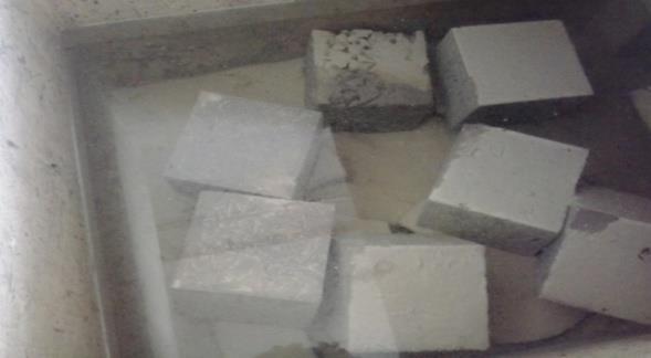
•Amould of Dimensions 150X 150 X 150 mm are used forcastingofcubes.
• OPC 53 Graded cement, M25 Graded Concrete, and 42 mmHDPEBalls
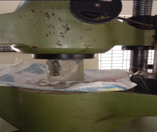
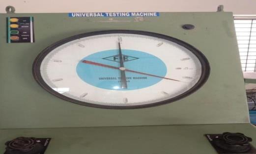
• A Universal Testing Machine (UTM) are used for Compressiontesting
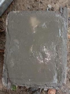
Casting Specimen
• The 150 x 150 x 150 mm specimen was used for compressive strength test. Totally 6 no’s of cubes were casted.
• 3 cubes are using for Normal convectional slab and another3cubesforBubbleslabspecimenarecasted.
• The materials were taken as per M25 (1:1:3:0.38) and mixed well in dry condition. The required amount of water is added gradually. 150mm mould were greased well.
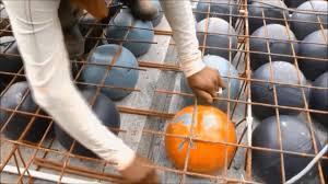
• The concrete was placed in three layers. At the end of eachlayer,thepolyethyleneballswereplaced.Eachlayer has9polyethyleneballs.
•TheMouldsareopened after24hours of time and the cubesareplacedinwatertankorsumpforcuring
The curing period is Settled for 7, 14, 28 days and used forcompressiontest.
Procedure
1.Specimens are taken out from Curing tank or sump aftercuringperiod
2.Thespecimenisdriedandcleanedwithcloth.
International Research Journal of Engineering and Technology (IRJET) e-ISSN:2395-0056
Volume: 11 Issue: 07 | July 2024 www.irjet.net
3.SpecimenisplacedatUTMandtightenthescrew.
4.Load is applied and noted the load at which the specimen is failed the compression strength of the Convectionalslabandbubbleslabspecimenbyformula
Compressive Strength (F) = Load applied/ Area of the cube. (P/A)
TheCompressivestrengthofconvectionalSlabSpecimen isfor7,14,28Days.
The Compressive Strength of Bubble Slab Specimen For 7,14,28Day.
p-ISSN:2395-0072
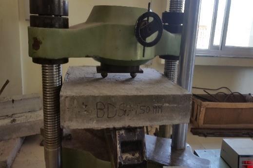
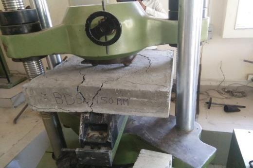
4.2 Compression Test of Convectional Slab and HDPE Balls introduced Slab. Comparison of Compressive Strength of Convectional and Bubble Deck Slab with Reinforcement
Comparative compressive test between a bubble deck slab and a conventional solid slab with reinforcement involves subjecting both types of specimens to axial loading until failure. This test allows for a direct comparison of the compressive strength and performancebetweenthetwoslabdesigns.
Materials and Machines Used
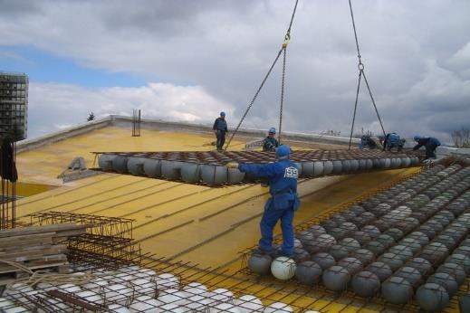
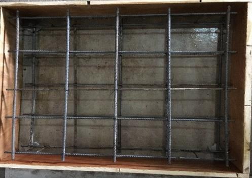
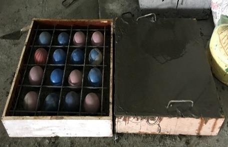
•Amould of Dimensions 700X 700 X 150 mm are used forcastingofSlabs
• OPC 53 Graded cement, M25 Graded Concrete and 90 mmHDPEBalls
•Fe50010mmDiaBars
• A Universal Testing Machine (UTM) are used for Compressiontesting.23CastingSpecimen
• The 700 x 700 x 150 mm specimen was used for compressive strength test. Totally 2 nos of Slabs were casted.
• 1 Slab is using for Normal convectional slab and another1SlabforBubbleslabspecimenarecasted.
• The materials were taken as per M25 (1:1:3:0.38) and mixed well in dry condition. The required amount of
International Research Journal of Engineering and Technology (IRJET) e-ISSN:2395-0056
Volume: 11 Issue: 07 | July 2024 www.irjet.net
waterisaddedgradually.Mouldwasgreasedwell.
• Reinforcement is made by Fe500 Steel of 10 mm Dia andplaced240mmspacingfromc/c.
• The concrete was placed with the polyethylene balls were placed between the spaces in the reinforcement anduse16HDPEballs
•Mouldsareopenedafter24hoursoftimeandthecubes areplacedinwatertankorsumpforcuring
• The curing period is Settled for 28 days and used for compressiontest.
p-ISSN:2395-0072
5.RESULTS AND CONCLUSION.
5.1 Results
The result of the compression test of comparison between convectional cube and HDPE balls cubes after curingof7,14,28days.
Table 1 TestResults
Cube HDPE Ball
Fig.12. GraphicalRepresentationofComparison betweenthecompressiontestofConvectionalCube& HDPEballsCube
The Result of Compressive test of Comparison between Convectional Slab and HdPE Slab with deflection on everyload
International Research Journal of Engineering and Technology (IRJET) e-ISSN:2395-0056
Volume: 11 Issue: 07 | July 2024 www.irjet.net p-ISSN:2395-0072
Convectional Slab HDPE Ball Slab
(KN)
Table.2 DeflectionasperLoadofConvectionalSlaband HDPEBallSlab
5.2 Conclusion
1. Load bearing capacity of Bubble Deck slab is high comparedtoconventionalslab
2. Bubble deck slab can be lesser (30% to 50%) to the weightofconventionalslab
3. The construction of Bubble deck slab can economicallycomparetoConventionalSlab
4.ThedeflectionofBubbledeckslabunderloadishigher comparedtoConventionalSlab
5. The Emission of the CO2 is lesser compared to ConventionalSlab
6. REFERENCES
1.Nizamud Doulah and Md.Ahsanul Kabir, “Nonlinear finiteelementanalysisofreinforcedconcreterectangular andskewslabs,”JournalofCivilEngineering,29(1).Pp.11,2001.
2.Martina Schnellenbach Held, “Punching behaviour of biaxial hollow slab, Journal of Cement and Concrete Composites,”Vol.24,Pp551-556,2002.
3.C. Marais, J.M Robberts and B.W.J van Rensburg, “Spherical void formers in solid slab,” Journal of the South African Institution of Civil Engineering, Vol.52, pp2-11,2010.
4.Sergiu Calin and Sergiu Baetu, “Nonlinear finite element modelling of spherical voided bi-axial concrete floor slabs,” International Symposium Computational CivilEngineering,Vol.08,pp.81-92,2011.
5.P. PrabhuTeja, S.Anusha and C.H Mounika, “Structural behaviour of bubble deck slab,” IEEEInternational Conference on Advances in Engineering, Science and Management(ICAESM),Vol.20,pp.21-41,2012.
6. A.N Prakash (2011), “The revolutionary concept in voided slabs”, Dimensions - A Journal of a N Prakash CPMCPvt.Ltd.,IssueNo.10,March2011.
7. Amer M. Ibrahim, Nazar K. Ali, Wissam D. Salman. (June 2013). “Flexural capacities of reinforced concrete two-way bubble deck slabs of plastic spherical voids”, Diyala Journal of Engineering Sciences, ISSN 1999-8716, Vol.06,No.02,June2013.
8.Arati Shetkar and Nagesh Hanche. (2015). “An experimental study on bubble deck slab system with ellipticalballs”.ISSN:0976-28764
9.Bhagyashri G. Bhade and S.M Barelikar AN EXPERIMENTAL STUDY ON TWO WAY BUBBL E DECK SLAB WITH SPHERICAL HOLLOW BALLS International Journal ofRecent Scientific Researc h Vol.7, Issue, 6,pp. 11621-11626,2016
10.CalinS,andAsavoaieC(2010).Experimentalprogram regarding “Bubble Deck” concrete slab with spherical gapsIntersections/Intersectii,4(7)-1,pp.34-40.
11. AarathiShethkar, Nagesh Bhanche. (2015). An Experimental Study on Bubble Deck Slab System with EllipticalBalls.Volume12.Issue1.Pages21-27.
12.Annamiya, Anup Willson, Khadeehga, Mithoon, Mohammed Sheebili, Nincy C.K. (2018). Bubble deck slab. International Journal of Advance Engineering and ResearchDevelopment(IJAERD).Volume5.Issue4.April 2018.Pages2012-2015.
13. Aron Maake, MeenaksiKhadao. (2018). Experimental study on bubble deck slab by using HDPE balls. InternationalJournalofAdvancedInnovativeTechnology in 31 Engineering (IJAITE). Volume 3. Issue 2. March 2018.Pages96-100.
14. Bhagyasree Bade, Barelikhar. (2016). An Experimental Study on Two Way Bubble Deck Slab with Spherical Hollow Balls. International Journal of Recent
International Research Journal of Engineering and Technology (IRJET) e-ISSN:2395-0056
Volume: 11 Issue: 07 | July 2024 www.irjet.net p-ISSN:2395-0072
ScientificResearch(IJRSR).Volume7.Issue6.June2016. Pages11621-11626.
15. Bhagyasree Bade, Suryavanshi. (2017). Structural Behaviour on Two Way Bubble Deck Slab Using Hollow Spherical Balls. Vishwakarma Journal of Engineering Research (VJER). Volume 1. Issue 2. June 2017. Pages 116-124.
© 2024, IRJET | Impact Factor value: 8.226 | ISO 9001:2008 Certified Journal | Page510