
International Research Journal of Engineering and Technology (IRJET) e-ISSN: 2395-0056
Volume: 11 Issue: 07 | July 2024 www.irjet.net p-ISSN: 2395-0072

International Research Journal of Engineering and Technology (IRJET) e-ISSN: 2395-0056
Volume: 11 Issue: 07 | July 2024 www.irjet.net p-ISSN: 2395-0072
Ashwini R Chengta1 , Dr. Babu Reddy2
1 Department of Mechanical Engineering, VTU CPGS Kalaburagi, Karnataka, India.
2 Assistant Professor & Program Coordinator Department of Mechanical Engineering, VTU CPGS Kalaburgi, Karnataka, India. ***
Abstract - In the feild of fast prototyping, 3D printing is seeingastreaminpopularitythankstoitsabilitytoquickly produceawiderangeofcomplexshapesandstructures.This production technique employs a computer-aided design (CAD)blueprinttogenerateatangibleprototype.Itworksby layeringmaterialtobuildtheprototype.Amajorbenefitof this approach is its sucessfullness in creating convoluted parts with little to no material being wasted. There are numerous methods for rapid prototyping on the market, with fused deposition modeling (FDM) standing out as a favorite.Thepredictableof3DprinteditemsmadefromPLA (PolylacticAcid)areshapedbydifferentprocesssettingsand thematerial'sinherentproperties.Inthisstudy,theeffectof condemnatoryprocesssettings,likelayerthickness,volume fill,andprintingrate,onthematerial'smechanicalstrength wasinvestigated.Theresultsspecifythatahighervolumefill resultedingreatertensilestrength,whereasloweringthe printingrateanddecreasinglayerthicknessimprovedthe material's mechanical strength. The experimental results werecomparedtothoseforecastbyANSYS.
Key Words: FDM, Additive Manufacturing, 3D Printing, PLA,CAD.
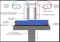
FusedDepositionModeling(FDM)shinesasafavoredand environmentallyfriendlymethodofadditivemanufacturing (AM).It'swidelyusedinboththeconsumerandindustrial realmsforthecreationofintricate3Dobjects,asdepictedin Figure1,whichshowsthevariouspartsofanFDMprinter that work together to quickly produce components with littlewasteofmaterialandtools.Theprocessstartswiththe designanddevelopmentofthemodelusingcomputer-aided design(CAD)software.Afterward,thefilemustbeconverted intoaformatthattheFDM3Dprintercanunderstand.This conversiontypicallyinvolvestheuseofthestandardtriangle language (STL) and specialized software is needed to transformtheCADfileintoSTL.Next,steppermotorsmove the material, in the shape of a solid filament, through the nozzle.Thematerialisheatedbytheextrudertoaspecific temperature,causingittomelt,anditisthenplacedontothe platform. The material cools quickly and sticks to the platform.Subsequently,theprinterfollowsanumericalGcode sequence in a layer-by-layer manner, repeating this stepuntiltheobjectisfinished.
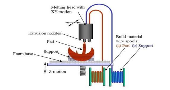
1:componentsofFusedDepositionModeling
A variety of substances, including low-temperature metal alloys and composites, can be utilized in FDM, but the primarymaterialsforthistechniquearethermoplasticsand polymer-based composites. The success of creating a productwithdesirablemechanicalcharacteristicsislinked to factors such as the orientation of the build, the pattern anddensityoftheinfill,thetemperatureofthenozzle,the sizeofthenozzle,therateatwhichtheprintingisdone,and thethicknessofeachlayer.Inadequateconditionsandlow temperatures can lead to problems during the printing process, such as warpage and shrinkage. It's important to mentionthatdeterminingtheelongationatbreak,Young’s modulus,andtensilestrengthisessentialforimprovingthe mechanical properties of isotropic and anisotropic engineering plastics. One of the challenges of the FDM method is the need for support structures to prevent materialdroppingsandtoreducegapsforbetteradhesion. However, these support structures can affect the surface texture and the quality of the areas where supports are placed, making them appear rough and of lower quality. AnotherissuewithFDM-printedpartsisthestaircaseeffect, whichoccursduetothewaylayersbindtogether.
Ahn et al [1]. Examined the experiment design and determinedthatthedesignoftheexperiment,includingthe airgapandrasterpatternorientation,influencesthetensile strengthofthepartproducedthroughFDMprocesses,while the width of the raster pattern, the temperature of the model,andthecolordonotsignificantlyimpactit.Theyalso conducted a comparison between the tensile strength of FDMpartscreatedatvariousrasterpatternanglesandair gap versus those produced using injection molding
International Research Journal of Engineering and Technology (IRJET) e-ISSN: 2395-0056
Volume: 11 Issue: 07 | July 2024 www.irjet.net p-ISSN: 2395-0072
techniques.Thematerialusedforbothfabricationmethods is ABSP400. FDM parts with a no air gap have a tensile strengthrangefrom10%to73%,peakingat0°anddipping to minimum at 90° in the direction the load is applied. However,partswithanairgapshowanotableincreasein tensile strength at certain raster pattern angles but still remainlessthanthestrengthofinjectionmoldedparts.Out ofallthespecimens,onlyone,withamixedorderoflayers' raster angles ranging from 45° to -45°, broke in the transversedirection.Thisspecimen'sfailureoccurredata 45°direction.Ananalysisofthespecimensmadewiththe axisofthepartperpendiculartothetableversusthosemade paralleltothetablefoundthatthepartsmadeperpendicular showed lesscompressive strength.From these findings, it was determined that the tensile strength of FDM parts is directional, meaning its strength varies in different directions.
MohammadHossainetal[2].Theobjectivewastoenhance the tensile mechanical strength of parts created through FDMbytweakingtheFDMprocessingsettings.Thesettings are set by the user through Insight, the software used for preparing files for most FDM devices. Despite Insight seemingtosuggestthattheroadsshouldbeuniformlylaid andconnected,a visual inspectionofthematerial showed thattheroadswerenotalwaysproperlyconnected,creating gaps that weakened the mechanical strength. Hence, this studydetailsthetensilemechanicalstrengthcharacteristics ofsamplescreatedusingthreedifferentsetsofparameters: the default or standard parameters, the Insight's versionspecific parameters, and an approach that relies on visual feedback.Comparingthesamplescreatedwiththedefault approachtothosemadeusingvisualfeedbackinsomecases showedanimpressiveimprovementintheultimatetensile strength, reaching up to 19% higher than the standard parameters.Futureresearchcouldexploretheimpactofthe orientationofthebuildandthethicknessofthelayersonthe mechanicalstrengthofFDMparts.However,increasinglayer thicknesscouldpotentiallyreducethebuildtime.Whilethe visualfeedbackmethoddoeshelptominimizegaps,itdoes notfullyeliminatethem,suggestingthatfurthertestscould bedonetounderstandhoweliminatingairgapsaffectsthe densityofthesamples.
S.H.Masood et[3] al. Fused deposition modeling (FDM) standsoutasaleadingtechnologyinadditivemanufacturing foravarietyofengineeringneeds.Itwasfirstmadeavailable for commercial use in the early 1990s by Stratasys Inc., a company based in the USA. The quality of parts produced throughtheFDMmethodislargelyinfluencedbytheprecise selection of its process variables. Therefore, it's crucial to pinpointtheFDMprocessparametersthathaveasignificant impactonthequalityofthepartscreated.Overthepastfew years,researchershaveinvestigatednumerousstrategiesto enhance the mechanical characteristics and quality of the parts by employing different experimental design methodologies and principles. This paper intends to
summarizetheresearchconductedtodateinidentifyingand refiningtheprocessparametersoftheFDMmethod.
Most commercially available rapid prototyping machines use one of six techniques. At present, trade restrictions severely limit the import/export of rapid prototypingmachines,
1SelectiveLaserSintering:
2Stereolithography(SL)
3FusedDepositionModelling(FDM):
Fused Deposition Modelling (FDM):
FusedDepositionModeling(FDM)wasfirstintroducedby Stratasys,locatedinMinnesota,USA.Itinvolvesextrudinga finematerialthroughanozzlethat'sinasemi-liquidstate, whichisthenspreadacrossabase.Thisnozzleispositioned inboththeX-Yplanetocreateathin,layeredcross-section ofthecomponent.Witheachlayerthat'sextruded,itadheres tothelayerbelowit,causingittosolidify.Thebaseisthen lowered in relation to the nozzle, and the process is repeated,addinganotherlayerontopofthepreviousone. Anothernozzleisutilizedtoextrudeadifferentmaterialto construct support frameworks for the component as necessary. Once the component is finished, the support frameworksareremovedfromit.
This technology involves 3D printing, which employs a deviceequippedwithacomputer-operatednozzletocreate an ongoing thread of plastic. On a bigger scale within industrial machinery, this process takes place within an environmentthat'stightlyregulated,maintainingaprecise temperature and conditions. Yet, in cheaper 3D printers, acievingsuchaccuracyisn'tpractical.
Applicationsoffuseddepositionmodeling(FDM).
•Productionofprototypesfortestingpurposesintermsof sizeandfunction
International Research Journal of Engineering and Technology (IRJET)
Volume: 11 Issue: 07 | July 2024 www.irjet.net
•Creation of parts made from materials that have been deemed suitable by regulatory bodies for aerospace applications
•TheabilitytoapplysurfacecoatingtoABSparts
•Productionofsmallquantitiesofitemsforhigh-volumebut low-costmanufacturingprojects
•Creationofpartsthataremoreeconomicaltoproduce
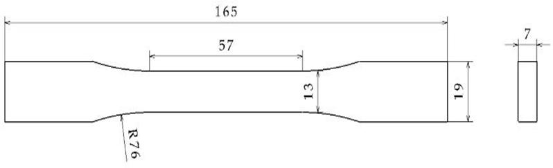
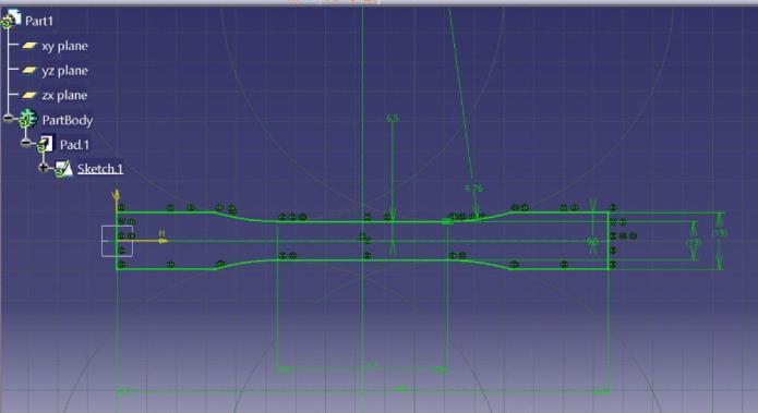
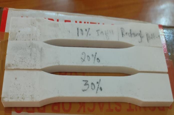
For specimen preparation, the CAD files of a dogbonetensilespecimenbyTypeIofASTMD638standard40 were modelled in CATIA software and exported as STL format.TheimportedfilethenwasconvertedtotheSTLfile tobeabletobereadablebytheFDMmachine.Theprocess parameterssuchaslayerthickness,volumeinfill,andprint speedwereconsideredfordifferentcombinations.Allother process parameters such as shell thickness, print temperature,diameteroffilamentandnozzlesizewerekept constant for all samples which their values were listed in Table1. These parameters were selected from the recommendations of 3D printer manufacturer and our experiences about the quality of different 3D printed specimens with good mechanical strength. The specimens wereprintedandselectedforfurtheranalysis.
Samplepreparationprocess
The permanence of parts made from PLA is influencedbyseveralfactors.Inthisresearch,threefactors
thatcouldbeadjustedwereidentified:thethicknessofthe layers,theamountofmaterialusedbetweeneachlayer(also knownasinfilldensity),andtherateatwhichtheprintingis done.Thesefactorswerevariedduringtheexperiments.The partsweremadeusingaGlobal3DPramaan3Dprinter.The setupforeachsetoffactorsincludedlayerthicknessoptions of0.1mmand 0.2mm,infill densitiesof10% , 20% and 30%,andprintspeedsof20mm/secandThespecificsetups forthefactorsaredetailedinTable1.
Afterthesamplesweremade,theywereputtothe test. To carry out these experiments, a standard testing device (STD) was used to check the materials' ability to withstandstretchingandcompression.Stiffnessisoneofthe most important physical properties often tested. For the stretchtest,thepartsneededfollowedtheguidelinessetby the American Standard for Testing and Materials (ASTM) D638, a standard designed to measure the stretching properties of thermoplastics. The sample materials were shapedlikedumbbellsforthistest.
International Research Journal of Engineering and Technology (IRJET) e-ISSN: 2395-0056
Volume: 11 Issue: 07 | July 2024 www.irjet.net p-ISSN: 2395-0072
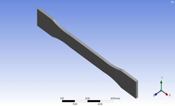
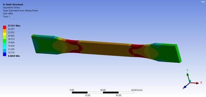
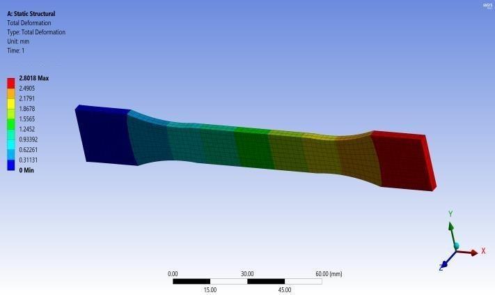
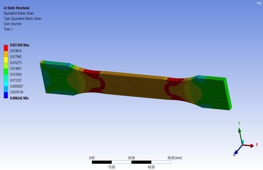
To more accurately understand how structural modifications, affect test results, we incorporated simulations with our experimental work. In this case, we employedthefiniteelementmethod(FEM)foranalysis.The materialwasconsidereduniformandisotropic,relyingon stableengineeringparameterssuchasYoung'smodulusand Poisson’sratio,whichwerecalculatedfromdatafromtensile tests. The strategy involved breaking the problem into smaller,moresolvablecomponentsthroughlinearfunctions and tetrahedron elements, ensuring a solution's rapid convergence through analysis. All required preliminary tasks, like generating 3D models, establishing boundary conditions,andsegmentingthemodelintotriangles,were finished with ANSYS, an effective tool for these tasks. A conventional uniaxial testing simulation was then carried out under different stress conditions. In this process, one end of the specimen was secured, and the other end was subjectedtoastressappliedperunitarea.
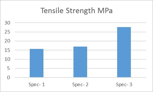
This research first looked into how the parameters of the FDM process, such as layer thickness, volume fill, and
International Research Journal of Engineering and Technology (IRJET) e-ISSN: 2395-0056
Volume: 11 Issue: 07 | July 2024 www.irjet.net p-ISSN: 2395-0072
printingspeed,affectthePLAmaterial.Additionally,tensile strengthtestswerecarriedout.Thelocatingshowedthatthe idealsetupdemandsalayerthicknessof0.3mm,avolume fillof30%,andaprintingspeedof20mm/s.Amongthese parameters,thehighesttensilestrengthwasachievedat27 MPa.Subsequently,theresultinoutcomeswerecompared withthepredictionsgeneratedbyANSYSsimulations.The simulateddatacloselyalignedwiththeactualexperimental results.
1. Ahn Sung Hoon, Montero Michael, Odell Dan, Roundy Shad, Wright Paul K. (2002). Anisotropic materialpropertiesofFDMABS,Rapidprototyping journal,8(4):248-257.
2. Omar A. Mohamed, Syed H. Masood, Jahar L. Bhowmik, Optimization of FDM process parameters:areviewofcurrentresearchandfuture prospects.
3. Mohammad Shojib Hossain, Jorge Ramos, David Espalin, Improving Tensile strength Mechanical Properties of FDM-Manufactured Specimens via ModifyingBuildParameters.
4. ConstanceZiemian,ImprovingTensileMechanical Properties of FDM-Manufactured Specimens via ModifyingBuildParameters.
5. Dr. K. G. Dave, An Experimental Investigation of EffectofProcessParametersonSurfaceRoughness ofFDMBuiltParts.
6. S.Dinesh Kumar, Parameter Optimization of ABSM30iPartsProducedbyFDMforMinimumSurface Roughness.
7. MAlhubail,Taguchi-basedOptimisationofProcess ParametersofFDMforImprovedPartQuality.
8. Milosevic M,StoofD,PickeringKL.Characterizing the mechanical properties FDM natural fiber recycledpolypropylenecomposites. JComposSci. 2017;1:7
BIOGRAPHIES

Dr. Babu Reddy Assistant Professor&ProgramCoordinator Department of Mechanical Engineering,VTUCPGSKalaburgi, KarnatakaIndia.
Ashwini R
Chengta Received B.Edegree in Industrial and productionEnginee Karnataka,India.
ringfromPDA Engineering College Kalaburgi Karnataka,India.intheyear2021 Now Pursuing M.Tech degree in Mechanical Machine Design Engineering from VTU CPGS Kalaburgi,