
International Research Journal of Engineering and Technology (IRJET) e-ISSN: 2395-0056
Volume: 11 Issue: 07 | July 2024 www.irjet.net p-ISSN: 2395-0072

International Research Journal of Engineering and Technology (IRJET) e-ISSN: 2395-0056
Volume: 11 Issue: 07 | July 2024 www.irjet.net p-ISSN: 2395-0072
Vidya Sadashiv Khanure1 and Vathsala2
1PG student, Dept. of Civil Engineering, BIT college, Bangalore, Karnataka, India
2Associate Professor, Dept. of Civil Engineering, BIT college, Bangalore, Karnataka, India
Abstract – The diagrid structural system has gained popularity recently in tall buildings because of its flexibility and structural efficiency. Each storey height's diagrid structure is planned with diagonals positioned at varying uniform angles and angles that progressively change as the building height increases. Due to the presence of inclined columns, the diagrid construction resists lateral loads more effectively than typical frame buildings with outside vertical columns. The slanted columns that are positioned at the outside edges of the structures in thediagridsystemactaxially to resist lateral loads because of their triangular shape, the diagonal members of diagridstructuralsystemsarecapableof supporting lateral forces and gravity loads. This study considers a thirty-storey high-rise building with different shapes of buildings, a different angle diagrid, and no diagrid structure. They are modelled for dead, live, seismic, and wind loads using ETABS software for zone 3 of medium soil. Scale factor is taken into consideration in both the X and Y directions according to IS code, and linear static and dynamic analysis has been performed. It is necessary to compare the structures with and without diagrids in order to compute the findings. It is anticipated that the diagrid system will improve the performance of lateral load and gravityloadresistancefor high-rise buildings.
Key Words: Highrisebuilding,Anglediagridsystem,Lateral load,seismicloads,ETABSsoftware,varyingangles.
Structuralengineershavecomeupwithinnovativedesigns throughoutthehistorytodecreasethelateralmovementof high-rise buildings. The diagrid system isa structural and architecturalmarvel,knownforitsdualbenefitsofstrength and aesthetics. It features a diagonal lattice of structural membersthatnotonlyprovidestabilitytotallbuildingsbut also lend them a distinctive and iconic appearance. This system'suniquedesignallowsarchitectstocreatevisually stunningstructureswithunconventionalshapesandfacades, setting them apart as urban landmarks. Beyond its visual appeal, the diagrid system enhances interior spaces by eliminatingtheneedfornumerousverticalcolumnsorshear walls.Theopenlayoutprovidesflexibilityforinteriordesign andspaceutilization,makingitespeciallyadvantageousfor commercialandofficebuildings.Additionally,itefficiently distributes lateral forces like wind and seismic loads,
reducing the need for excessive bracing and reinforcing materials, thereby enhancing both functionality and sustainability. In essence, the diagrid system represents a harmonious fusion of form and function, making it a preferred choice for architects and developers seeking to constructiconic,efficient,andstructurallysoundbuildingsin modernurbanenvironments.
The principle underlying the diagrid structural system revolvesaroundtheutilizationofdiagonalmembersinplace of traditional vertical columns or shear walls. This innovativeapproachcapitalizesontheinherentstrengthof triangles, which are known for their stability and loadbearing capabilities. By strategically arranging these diagonalmembersinagrid-likepattern,thediagridsystem effectivelydistributestheforcesactingonabuilding,suchas wind and seismic loads, in a more efficient and balanced manner. This results in enhanced structural stability and reducestheneedforexcessivebracing,allowingforgreater designflexibilityandopeninteriorspaces.Theprincipleof thediagridsystemshowcasesthesynergybetweenformand function, where architectural elegance merges seamlessly with structural integrity to create iconic and resilient buildings.
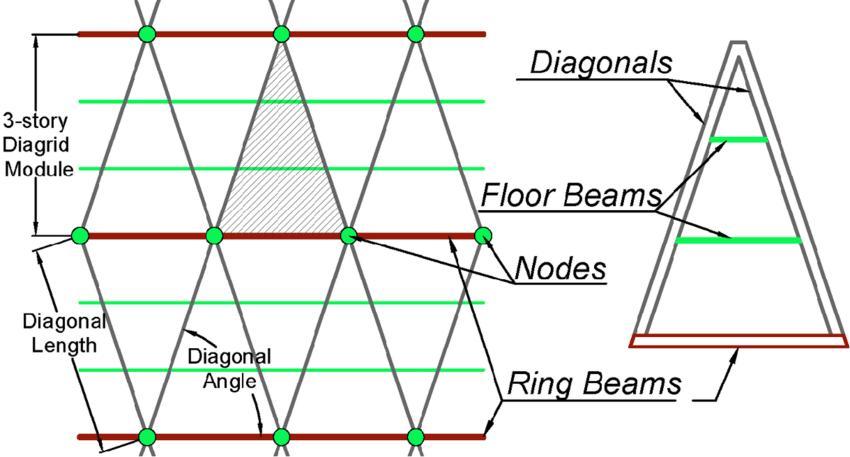
Fig-1: componentsofanglediagridsystem
International Research Journal of Engineering and Technology (IRJET) e-ISSN: 2395-0056
Volume: 11 Issue: 07 | July 2024 www.irjet.net p-ISSN: 2395-0072
Thediagridstructuralsystemsintallbuildingshavebeen well studied in the literature, which provides in-depth information on their dimensional considerations, sustainability,andefficiency.Tripathietal.(2016)carefully investigate how storey modules and diagrid angles affect structural behavior, taking into account factors like shear stresses, lateral displacement, and storey drift. In their thoroughcomparisonofdiagridandconventionalsystems, Deshpandeetal.(2015)highlightthebenefitsofthelatter, particularly with regard to load distribution and material efficiency. These advantages can be translated into real benefits, such as cost savings and flexible interior layouts, particularlyinbuildingsupto50meterswideby100meters high.Toelaborate,Panchaletal.(2014)performathorough investigationoverawiderangeofbuildingheights,from24 to60storeys,withdiagridanglesrangingfrom50.2°to82.1°, looking at important parameters including material consumption and top storey displacement. Furthermore, Janiaetal.(2013)examinestheparticularmeasurementsofa 36-storey diagrid steel skyscraper with a 36 x 36 m floor plan,focusingonthesystem'sdesignflexibilityandlateral load resistance. This study provides a sophisticated understanding of diagrid structural systems, offering insightfulinformationandusefulconsiderationsfortheiruse intallstructuredesign,especiallywithregardtodimensions andperformancemetrics.
Based on the literature review, from past few years, a conspicuousgapintheexistingresearchlandscapepertains to the limited exploration of alternative structural design strategiesconcerningangle-varyingdiagridsystems.While diagridstructureshavegarneredsubstantialattention,the majorityofstudieshavepredominantlyfocusedonuniform diagrids with fixed angles. The potential benefits and structural implications of incorporating varying angles withindiagridsystems,inthecontextofirregularstructures, remain largely unexplored. An in-depth analysis of these alternativedesignapproachescouldyieldvaluableinsights into their structural efficiency and performance
characteristics. Since, very few researches have been conductedonDynamicseismicanalysisofDiagridsystems, thisstudymainlyfocusesoncomparingtheperformanceof conventionalbuildingandvaryingDiagridsystemsunderthe effectofseismicloadsusingETABSsoftware.
Determining the behavior of RCC structure by providing differentanglesofdiagridanddifferentshapesofbuildings analysis using ETABS software. A typical R.C design of 30 Storey is considered for the analysis having six bays in X directionwithequivalentspacingof3.5mandsixbaysinY directionwithequivalentspacingof3.5m.Theplansizeis 21m x 21m. the floor-to-floor height is 3.5m and the total heightofthebuildingis105m.
Table -1: Building details
Numberofstories 30
Gradeofconcrete M40
Gradeofsteel Fe415
SizeofBeams 300mmx600mm
ThicknessofSlab 125mm
Sizeofdiagrids 500mmx500mmx20mm
Floor0-9:800mmx500mm,
SizeofColumns
Floor10-19:700mmx450mm,
Floor20-30:600mmx400mm
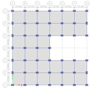
Fig – 2: PlanofC-shapedbuilding
International Research Journal of Engineering and Technology (IRJET) e-ISSN: 2395-0056
Volume: 11 Issue: 07 | July 2024 www.irjet.net p-ISSN: 2395-0072
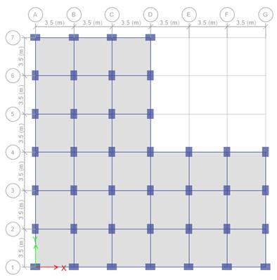
– 3: PlanofL-Shapedbuilding
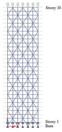
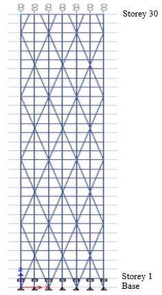
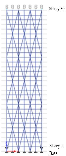
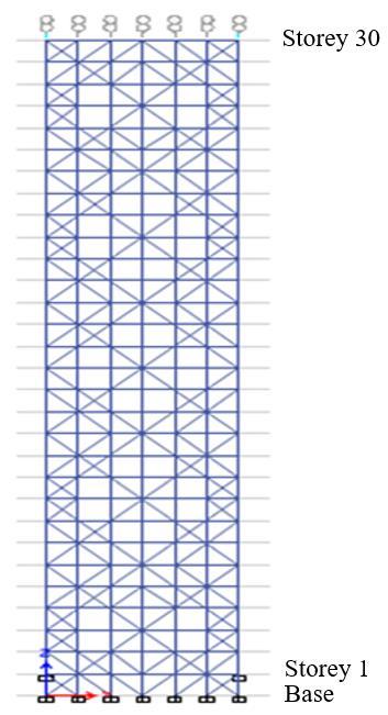
Fig – 4: Typicalfloorplan,elevationofDiagrid system.Elevationofbuildingat(a)63.44°(b)74.06°(c)78.60°(d)varying density
3D VIEW OF C- SHAPED BUILDING:
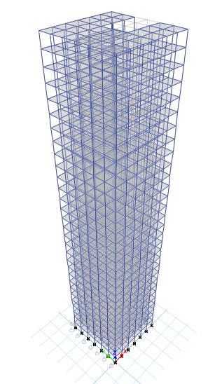
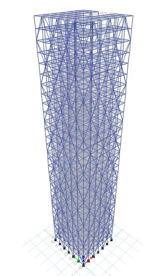
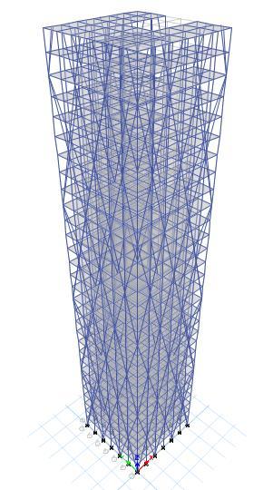
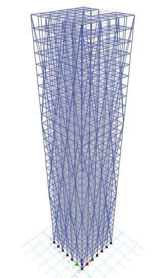
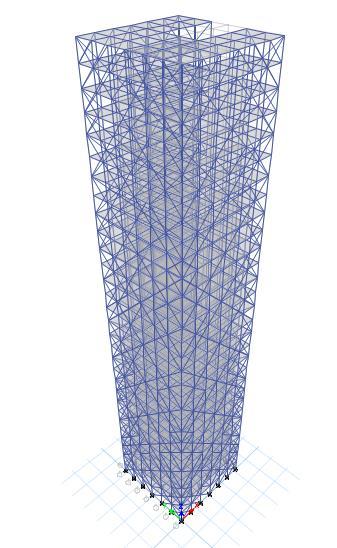
Fig- 4: 3DviewofDiagridsystemofC-shapedbuilding. (a)withoutdiagridsystem(A1),Diagridatangle(b)63.44°(A2),(c)74.06°(A3),(d)78.60°(A4),(e) Diagridswithvaryingdensity(A5)
International Research Journal of Engineering and Technology (IRJET) e-ISSN: 2395-0056
Volume: 11 Issue: 07 | July 2024 www.irjet.net p-ISSN: 2395-0072
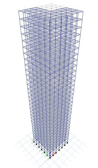
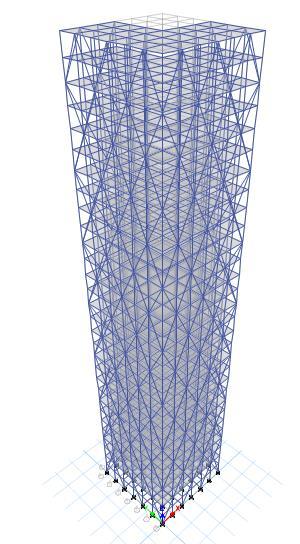
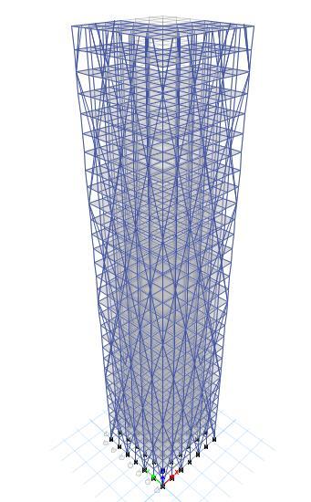
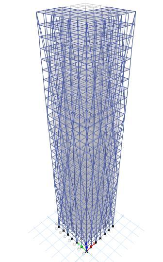
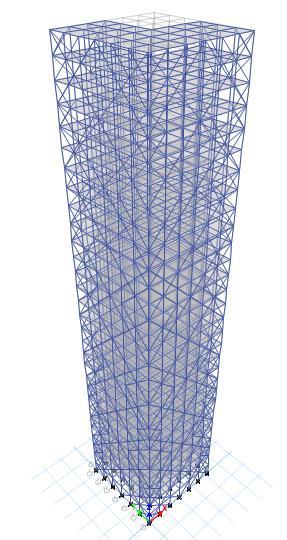
Fig- 5: 3DviewofDiagridsystemofL-shapedbuilding. (a)withoutdiagridsystem(B1),Diagridatangle(b)63.44°(B2),(c)74.06°(B3),(d)78.60°(B4),(e) Diagridswithvaryingdensity(B5)
Differenttypesofloadshavebeenconsideredandanalyzed fortheproposedbuilding.Theloadsthatareconsideredis self weight that is calculated by ETABS, floor finish of 1 kN/m2 andliveloadof3kN/m2
DYNAMICSEISMICANALYSIS:
According to IS 1893 (Part I): 2016, the following guidelineusedfor seismicexamination.
ImportanceFactor:1.2 (Clause7.2.3,Table-8)
SeismicZone:IV
ZoneFactor,Z:0.24 (Table-3)
Soiltype:TypeII (Clause6.4.2.1,MediumSoil)
ReductionFactor:5 (Clause7.2.6,Table-9,SMRF)
LOADCOMBINATIONS:
1.5(DL+SL) 1.5(DL+LL+SL)
1.2(DL+LL+SL+WX) 1.2(DL+LL+SL-WX)
1.2(DL+LL+SL+WY) 1.2(DL+LL+SL-WY)
1.5(DL+SL+WX) 1.5(DL+SL-WX)
1.5(DL+SL+WY) 1.5(DL+SL-WY)
0.9(DL+SL)+1.5WX 0.9(DL+SL)–1.5WX
0.9(DL+SL)+1.5WY 0.9(DL+SL)–1.5WY
1.2(DL+LL+SL+EQX) 1.2(DL+LL+SL-EQX)
1.2(DL+LL+SL+EQY) 1.2(DL+LL+SL-EQY)
1.5(DL+SL+EQX) 1.5(DL+SL-EQX)
1.5(DL+SL+EQY) 1.5(DL+SL-EQY)
0.9(DL+SL)+1.5EQX 0.9(DL+SL)–1.5EQX
0.9(DL+SL)+1.5EQY 0.9(DL+SL)–1.5EQY
Where,
DL–DeadLoad
SL-SuperDeadLoad
LL–LiveLoad
WX–WindLoadinXdirection
WY–WindLoadinYdirection
EQX–EarthquakeLoadinXdirection
EQY–EarthquakeLoadinYdirection
2024, IRJET | Impact Factor value: 8.226
International Research Journal of Engineering and Technology (IRJET) e-ISSN: 2395-0056
Volume: 11 Issue: 07 | July 2024 www.irjet.net p-ISSN: 2395-0072
4.1. MAXIMUM STOREY DISPLACEMENT OF C- SHAPED BUILDING
4.3. MAXIMUM STOREY DISPLACEMENT OF L- SHAPED BUILDING
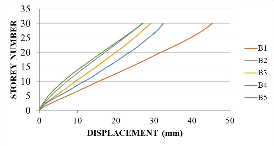
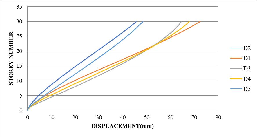
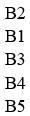
Chart -5:StoreyDisplacementC-shapedinX-direction
Chart -1:StoreyDisplacementC-shapedinX-direction
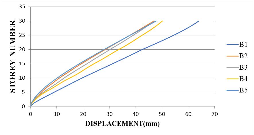
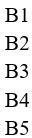
Chart -6:StoreyDisplacementC-shapedinY-direction
Chart -2:StoreyDisplacementC-shapedinY-direction
4.3. MAXIMUM STOREY DRIFT FOR C-SHAPED BUILDING
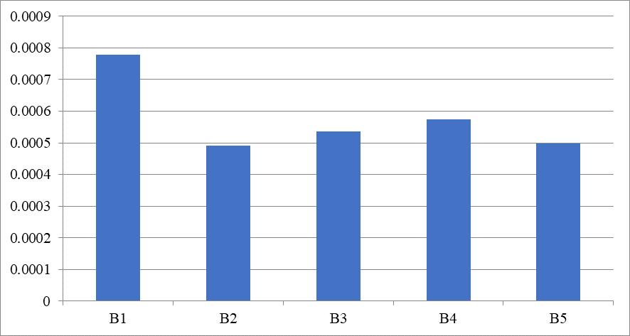
Chart -3:StoreyDriftofC-shapedbuildinginX-direction
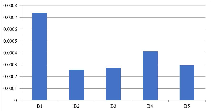
Chart -4:StoreyDriftofC-shapedbuildinginY-direction
4.4. MAXIMUM STOREY DRIFT FOR L-SHAPED BUILDING
Chart -7:StoreyDriftofC-shapedbuildinginX-direction
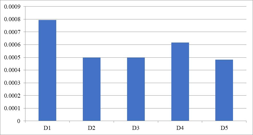
Chart -8:StoreyDriftofC-shapedbuildinginY-direction
International Research Journal of Engineering and Technology (IRJET) e-ISSN: 2395-0056
Volume: 11 Issue: 07 | July 2024 www.irjet.net p-ISSN: 2395-0072
From the charts i.e.,chart-1,2,3 & 4. itcan be observed thatC-shapedbuildingswithDiagridsystemwasefficient inreducingstoreydisplacementandstoreydriftinboth thedirections.
In conclusion, for C-Shaped 30-storied building, the results indicate that the structural efficiency increases withdiagridanglesof78.60°(A4),74.06°(A3),63.44°(A2) andvaryingdensity(A5)
From the charts i.e.,chart-5,6,7 & 8, itcan be observed thatL-shapedbuildingswithDiagridsystemwasefficient inreducingstoreydisplacementandstoreydriftinboth thedirections.
In conclusion, for L-Shaped 30-storied building, the results indicate that the structural efficiency increases with diagrid angles of 78.60°(B4), 74.06°(B3), varying density(B5)and63.44°(B2)
The current study evaluated the diagrid system's overall behavior for 30 storey irregular buildings. In order to compare conventional buildings with diagrid system buildingsforstoreydisplacementandstoreydriftinbothX and Y directions, seismic analysis was done using ETABS software. The analysis's findings led to the following conclusions.
1.Buildings with angle diagrid system perform more efficientlythanbuildingwithoutdiagridsystem.
2.Incontrast tovaryinganglediagridsystemitis inferred thatthe4storieddiagridangleof63.44°issuitablefor30 storiedbuildingstructure.
3.It could also be concluded that building structure with varyingdensityalsoperformsefficiently.
4.Buildings with diagrid system have less storey displacement and storey drift in contrast to buildings withoutdiagridsystem.
5.Consideringeverythingmentionedbefore,itcanbesaid that, though there was not a huge difference between diagridsystemswithdifferentangles,yetimplementation of diagrid system would be advantageous, placing of Diagrid system causes architectural & functional constraints.
Journals & Articles:
[1] Harshita Tripathi, Dr. Sarita Singla, “Diagrid structural system for R. C. Framed multistoried buildings”,
International Journal of Scientific & Engineering Research, Volume 7, Issue 6, June-2016 356 ISSN 2229-5518.
[2] R. D. Deshpande, S. M. Patil, S. Ratan, “Analysis and comparisonofdiagridandconventionalstructuralsystem”, InternationalResearchJournalofEngineeringandTechnology (IRJET), June 2015, Vol. 2, Issue 3, PP 2295–2300
[3] Nishith B. Panchal, Dr. V. R. Patel, Dr. I. I. Pandya, “OptimumAngleofDiagridStructuralSystem”, International Journal of Engineering and Technical Research (IJETR) ISSN: 2321-0869, Volume-2, Issue-6, June 2014
[4] Khushbu Jani a , Paresh V. Patel, “Analysis and Design of Diagrid Structural System for High Rise Steel Buildings”, Procedia engineering Volume 51, 2013.
Code books:
[5]IS456:2000,“Plainand ReinforcedConcrete– Code of practice(FourthRevision)”,BureauofIndianStandard,New Delhi.
[6]IS1893(Part1):2002,“CriteriaforEarthquakeResistant Design of Structures Part 1 General Provisions and Buildings”,BureauofIndianStandard,NewDelhi.
[7] IS 800:2007, “General Construction in Steel – Code of Practice(ThirdRevision)”,BureauofIndianStandard,New Delhi.
[8]IS875(Part1):1987,“CodeofPracticeforDesignLoads (OtherthanEarthquake)forBuildingsandStructuresPart1 DeadLoads–Unitweightsofbuildingmaterialsandstored materials (Second Revision)”, Bureau of Indian Standard, NewDelhi.
[9]IS875(Part2):1987,“CodeofPracticeforDesignLoads (OtherthanEarthquake)forBuildingsandStructuresPart2 Imposed Loads (Second Revision)”, Bureau of Indian Standard,NewDelhi.
[10]IS875(Part3):1987,“CodeofPracticeforDesignLoads (OtherthanEarthquake)forBuildingsandStructuresPart3 WindLoads(SecondRevision)”,BureauofIndianStandard, NewDelhi.