
International Research Journal of Engineering and Technology (IRJET) e-ISSN: 2395-0056
Volume: 11 Issue: 07 | July 2024 www.irjet.net p-ISSN: 2395-0072

International Research Journal of Engineering and Technology (IRJET) e-ISSN: 2395-0056
Volume: 11 Issue: 07 | July 2024 www.irjet.net p-ISSN: 2395-0072
Karan K. Gaidhankar 1 , Dr. Pradeep P. Tapkire2, Atul S. Chandanshive3
1Research Scholar at N.B. Navale Sinhgad College of Engineering, Solapur, Maharashtra, India-413255
2H.O.D. Civil Dept., N.B. Navale Sinhgad College of Engineering, Solapur, Maharashtra, India-413255
3Lecturer at Solapur Education Society’s Polytechnic, Solapur, Maharashtra, India-413255
Abstract - In this study, the interaction between soil and structure is a critical aspect influencing the performance and stability of reinforced concrete retaining walls. This study investigates the effects of soil structure interaction on such walls, aiming to enhance understanding and design methodologies. The interaction is examined through comprehensive analyses considering factorslikesoiltype,wall geometry, and reinforcement details. Key parameters such as lateral earth pressure distribution, walldeflection,andoverall stability are evaluated to ascertain how soil properties and structural design choices impact performance. Findings highlight the significanceofintegrateddesignapproachesthat consider both soil behavior and structural response, ensuring resilient and efficient retaining wall systems suitable for various environmental conditions and loading scenarios
Key Words: Soil-structure interaction, Retaining walls, Finite element method (FEM), Stability, Lateral earth pressure
Retainingwalls,suchasCounterfortRetainingWalls(CRWs), arefundamentalincivilengineeringforsupportingsoiland managing changes in ground elevation. CRWs utilize counterforts on the backside to enhance stability and are typicallybuiltusingmaterialslikeplaincementconcreteor occasionallystoneandbrickmasonry.Designingthesewalls requires careful consideration of potential failure modes: sliding,overturning,excessivesettlement,andscour.Sliding occurswhensoilmoveshorizontallyalongthebasedueto insufficient friction, making it a critical design factor. Overturning is prevented by ensuring the foundation and counterforts can withstand the moments caused by soil pressure.Settlementissuesaremanagedthroughrigorous soil analysis and proper foundation design to minimize unevensettling.Furthermore,measuresagainstscour,such aseffectivedrainageandprotectivebarriers,arecrucialfor maintainingthewall'sstabilityovertime.Engineersstriveto optimizethecross-sectionaldesigntoensurematerialsare efficientlyusedandthestructureremainsresilientagainst thesechallenges.ThisapproachensuresCRWsnotonlymeet immediate construction needs but also provide long-term reliabilityandsafetyacrossvariousengineeringprojects
To find the effect of Soil Structure Interaction on counterfort retaining wall based on Geometrical & geotechnicalparameters.
Thefollowingaretheobjectiveofresearchwork,
Exclusiveliteraturereviewiscarriedoutandtheunfocused areaisidentifiedwhichisconsiderasproblemforproposed dissertation. The effect of soil structure interaction on counterfortretainingwallisproposedtocarriedoutusing followingpoints,
• Analysis counterfort retaining wall sections for variousheights&variousloadingcondition.
• Finite Element analysis of above-mentioned faces with and without soil structure interaction for counterfortretainingwall.
• Identifytheparametersinfluencedbysoilstructure interactionanddevelopnon-dimensionalchartfor finding effect of soil structure interaction for geometrical&geotechnicalparameters
SoilStructureInteraction(SSI)forCantileverRetainingWalls elucidatestheintricaterelationshipbetweenthestructural element and the surrounding soil, highlighting the significanceofunderstandinghowexternalforcesactingon the wall and internal forces within the ground mutually influenceeachother.Thisinterdependenceunderscoresthe importance of considering soil-structureinteraction in the designandanalysisofcounterfortretainingwallstoensure theirstabilityandeffectivenessinsupportingsoilmassesand resistingexternalloads
Contributionsofresearchersarepresentedasfollows, Sunil Gupta, Tsung-Wu Lin, Joseph Penzien, ChanShioung Yeh [1] describedahybridmodelfortheanalysisof soil-structure interaction proposed which promises to be superiortothe19thtimemethodsofanalysis.Themodelling achievedbypartitioningthetotalsoil-structuresystemintoa near fieldanda farfield with hemispherical interface. The
International Research Journal of Engineering and Technology (IRJET) e-ISSN: 2395-0056
Volume: 11 Issue: 07 | July 2024 www.irjet.net p-ISSN: 2395-0072
near field consists of the structure, which analyzed and a finite region of soil around it was modelled by the finite element method. For thesemi-infinite far field,impedance matrix corresponding to the interface degrees of freedom developedwhichaccountsforthelossofenergyduetowaves travellingawayfromthefoundation.
Robert M. Ebeling [2] presentedareviewofpreviousworkin whichthefiniteelementmethodwasusedtoanalyzethesoilstructureinteractionofearthretainingstructuressuchasUframe locks, Gravity Retaining Walls, and basement walls. This method of analysis resulted in the computation of stressesanddisplacementsforboththestructureandthesoil backfill. Applications of the procedure showed the importanceofmodelingtheactual constructionprocessas closelyaspossibleandtheuseofanonlinearstress-strainsoil model. Additional requirements included modeling the interfacebetweenthesoilbackfillandthewall,whichused interfaceelements.Healsoincludedtworecentapplications of the finite element method for the analysis of earth retainingstructures,whichwasloadedsoheavilythatagap developed along the interface between the base of the structureanditsfoundation
Timothy D. Stark, Steven M. Fitzwilliam, Joseiph J. Vettel, Robert M. Ebeling [3] describedSoil-StructureInteraction ParametersforSilts.Theytriedtocharacterizethedrained and undrained stress-strain behavior of normally consolidated silts and clayey-silts. They used the result of their research to develop a database of hyperbolic stressstrainandMohr-Coulombstrengthparametersforsiltsand clayey-silts. They carried out extensive drained and undrainedtriaxletestsonsiltspecimenswithvaryingclay contents.Theyusedpercentagesofclayinthesiltmixtures were 0, 10, 30, and 50%. "The effect of density was investigated by compacting the triaxle test specimens at Standard Proctor relative compactions of 85, 90, 95, and 100%. They summarize the test results and the resulted hyperbolic stress-strain and Mohr-Coulomb strength parametersforthevarioussiltmixturesconsidered.
T. Kupsmy, Mark A. Zarco [4] inthisStudydescribedthe finiteelementcomputerprogramSOILSTRUCTusedinthe evaluation of soil structure interaction of earth retaining structure.
Mete Oner, William P. Dawkins [5] conducted a comprehensive analysis procedure to understand the soil structure interaction, mechanism involved in behavior of floodwall systems. They used finite element method with suitablemodelofthesoilstructureinterface,nonlinearsoil behavior,andloadingsequence.Ontestsection,theyusedan existedfloodwallforverificationofanalyticalmodel.
Eduardo Kausel [6] Describesearlyhistoryofsoil–structure interaction. The early history of Soil Structure Interaction whichliesattheintersectionofsoilandstructuralmechanics, soil and structural dynamics, earthquake engineering,
geophysics and geo-mechanics, material science, computational and numerical methods, and diverse other technicaldisciplines.
Dr. S. A. Halkude, Mr. M. G. Kalyanshetti, and Mr. S. H. Kalyani [7] the author worked on study of Soil Structure InteractionEffectonSeismicResponseofR.C.Frameswith Isolated Footing. The author investigated the effect of soil flexibility on the performance of building frame. Two SSI modeswasconsideredfortheanalysis;onereplacedsoilby springofequivalentstiffness(DiscreteSupport)andsecond by considered the whole soil mass (Elastic Continuum). Symmetric space frames rested on isolated footing of configurations 2 bay 2 storey (2X2X2), 2 bay 5 storey (2X2X5) and 2 bay 8 storey (2X2X8) was considered with fixedbaseandflexiblebase.Thespringmodelwasdeveloped by using stiffness equation along all 6 DOF and elastic continuummodelwasdevelopedbyFiniteElementMethod using SAP-2000. For SSI study three types of soil was consideredi.e.Hard,MediumHardandSoftSoil.Thedynamic analysiswascarriedoutusing ResponseSpectrum,givenin IS1893-2002.Theinfluenceofsoilstructureinteractionon variousstructuralparametersi.e.naturaltimeperiod,base shear, roof displacement, beam moment and column moment was presented. The study reveals that the SSI significantlyeffectsontheresponseofthestructure.Finite ElementMethodhasprovedtobetheeffectivemethodfor considerationofelasticcontinuumbelowfoundation.
K. Senthil, M. A. Iqbal & Amit Kumar [8] Author had worked on three-dimensional (3D) finite element simulations performed in order to study the response of cantilever and counterfort retaining walls subjected to lateral earth pressure using ABAQUS/Standard. Four retaining walls with different geometrical configurations wasanalyzedincludingthreecantileverandonecounterfort wall. The obtained results compared, and the mechanics involvedinthebehavioroftheretainingwallwasdiscussed. Thelateral displacement,vertical settlement,andstresses developed in each component of the retaining wall was studiedandcomparedwiththeotherwalls.Thechoiceofthe retaining wall based on the economic analysis was also discussedandcompared.
Dr. P. P. Tapkire [9] in this research work author had workedonOptimizationofgravityretainingwallprofileby introducingcavity.Inwhichthemainaimofthispaperwas todevelopacosteffectiveandstructurallyefficientprofileof gravityretainingwall byintroducingcavityinthesection. Forthis,varioussectionsizesofgravityretainingwallwas analyzedandaccordinglyprofilewasselectedandthenafter selectionofanappropriateprofileofgravityretainingwall stability calculations was carried out for various heights using„C‟programmingbystrengthofmaterialapproach.
Ms. Patil Swapnal V. [10] in this study, Effect of Soil StructureInteractiononGravityDam.Theeffectongravity dam had been examined using finite element analysis
International Research Journal of Engineering and Technology (IRJET) e-ISSN: 2395-0056
Volume: 11 Issue: 07 | July 2024 www.irjet.net p-ISSN: 2395-0072
softwareANSYS14.Thegravitydamcompletelyrestingon soil media and surrounded by soil media. The relevant amount ofsoilaroundand bottomofthegravity damhad beenmodeledtosimulatethein-situconditions.Thegravity dam was analyzed using dynamic loading in transient analysisusingImperialValley(1940)earthquakerecordwas included. Analysis of the gravity dam carried out and the influence of soil properties studied at the region of transversesections,whichexhibitedtheresponseintermsof stressanddeformationwithsignificantdifference
Snehal R. Lahande [11] Analytical Study of Cantilever RetainingWallIncludingEffectofSoilStructureInteraction. Theinfluenceofthedifferenttypesofsoilonthedifferent heightsofthewallwasaddressed.Acantileverretainingwall was considered and modeled for the soil-structure interactionusingfiniteelementpackageSAP2000Version 14.0.0. Dynamic distress and response of a cantilever retaining wall was studied considering six degrees of freedomsystem.Forthevalidationpurposeoftheretaining wall,supportconditionswereconsideredtobefixed.Forthe analysis, the inputs are density of concrete, modulus of elasticity of concrete, density and SBC of soil, modulus of elasticityofsoil,angleofinternalfrictionandloading(active and passive earth pressure). The targeted output was maximum lateral displacement. The response spectrum inputsweregiventotheretainingwallforallthethreetypes of soils (soft, medium, soft rock and hard rock) and three types ofseismic zones(III, IVand V).After the analysis,it wasobservedthatthepercentagevariationinthedeflection is900%(avg)towardsthefixedendandconvergesto1% towardsthefreeendwhencomparedwithclassicalmethod. Asthestiffnessofthesoilincreasestherewasareductionin deflectionandastheheightoftheretainingwallincreases therewasanincreaseinthedeflectionattheirfreeends.The deflectionincreaseswiththeincreaseinseismiczonevalue.
Eko Tavip Maryanto, Rezza Ruzuqi, and Victor Danny [12] TheauthorshaveworkedonStrengthAnalysisofSoil Retaining Wall Using Numerical Method of Manokwari Landfill.Theauthorinvestigatedthatthemechanicaleffects of soil retaining wall in the three types of designs of the landfills by 2D finite element analysis. The results could provide a reference for building to withstand the active lateral compressive forces of soil and water. The contribution of this study was sufficient for providing a functionalstrengthofretainingwalls.FEM(FiniteElement Method) used in analyzing the compressive strength of retainingwall.Theresearcherused2Danalysistodetermine thecompressivestrengthofthesoilontheretainingwallof the landfill in Manokwari City. The retaining wall in this studywasvariedbasedonthesethreeformsoftheretaining wall.Accordingtotheliteratureandthethreedifferentfinite elementnumbersbasedonthesoftware.Ansyssoftwarewas usedtosimulatethecompressivestrengthofretainingwalls against the ground. The results found and compared. The
resultsobtainedindicatedthatthegeometrydesign2hada bettersafetyvaluewhencomparedtotheothers.
Structural engineering and geotechnics are intertwined disciplines essential for the accurate analysis of civil engineeringstructures.Effectivesoil-structureinteraction (SSI)modelingisvitaltocapturetherealbehaviorofboth thesuperstructureandsubgrade.Structuralengineersoften usedetailedmodelsforstructuresbutsimplifythesubgrade, whilegeotechnicalengineersuseadvancedsoilmodelswith simplifiedstructures.Combiningadvancedmodelsfromboth fields would demand unrealistic computation times, highlightingtheneedforsimplifiedSSImethods.Theimpact ofthesesimplificationsonresultsisacrucialareaofinterest, as opinions differ on the best approach to model SSI accuratelyinpractice.
In civil engineering, structural elements like foundations, pavements,retainingstructures,andtunnelsofteninteract directly with the ground, creating what's known as soilstructureinteraction(SSI).Thisinteractionrequiresboththe structure and the ground to deform together due to their physical contact. Historically, SSI was often neglected for simplicity,butadvancesintechnologynowmakeiteasierto consider, although it can still be complex and timeconsuming.SSIcanbemodeledusingtwomainapproaches: thestructuralapproach,whichusessimplifiedelementslike springs and beams, and the continuum approach, which appliesdifferentialequationstosimulatesoilbehavior.The Winklermodel,apopularstructuralmethod,representsthe subgradewithverticalsprings,simplifyingimplementation butpotentiallyoversimplifyingsoilbehavior
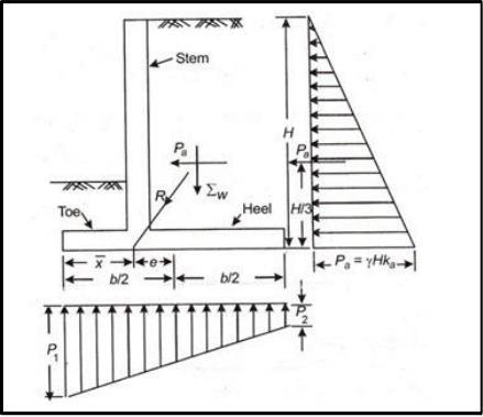
Varioustypesofloadsandforcesactonaretainingwall,and theircalculationisessentialforitsdesign.Theseforceson the retaining wall depends on multiple factors which are discussed.Therearevarioustypesofloadsandforcesacting onretainingwall,whichare:
1.Lateralearthpressure
2.Surchargeloads
3.Axialloads
4.Windonprojectingstem
5.Impactforces
6.Seismicearthpressure
7.Seismicwallself-weightforces
International Research Journal of Engineering and Technology (IRJET) e-ISSN: 2395-0056
Volume: 11 Issue: 07 | July 2024 www.irjet.net p-ISSN: 2395-0072
Retainingwalldesigncouldincludeanyorallofloadsand forceswhichareexplainedinthefollowingsections:
LateralEarthPressureActingonRetainingWallThemain purposeofretainingwallconstructionistoretainsoil;thatis why soil lateral earth pressure is a major concern in the design.Slidingsoilwedgetheoryisthebasisformostofthe theoriesby whichlateral earthpressureiscomputed.The wedgetheorysuggeststhatatriangularwedgeofsoilwould slidedowniftheretainingwallwereremovedsuddenly,and the wall has to sustain this wedge soil. Figure shows free bodylateralforcesactingonretainingwalls
4. Research Methodology
Inthesteelindustry,twoprimarymethodsforconstructing industrialstructuresareConventionalSteelBuildings(CSB) andPre-EngineeredBuildings(PEB).CSBsusestandardhotrolled steel sections with varying designs, often incorporating concrete columns for support. They are versatilebutcanresultinhighermaterialwastageandlower constructionprecisionduetoboltedorweldedconnections.
On the other hand, PEBs are designed and fabricated in factories to minimize material usage and streamline constructiontime.Theyareknownfortheirefficientuseof steel, quick assembly, and reliable performance under diverseconditions,supportedbystringentdesignstandards like IS 875 and IS 800 for load analysis and steel design, respectively.ThiscomparisonhighlightsPEBs'advantagesin cost-effectiveness and rapid deployment, making them a preferred choice for many industrial applications seeking bothefficiencyanddurability.
4.2 Analysis of CRW using FEM with & without SSI
Finalized crosses section of CRW for various heights & profile are analyzed with & without soil mass using finite elementpackageofANSYS18.0.Whileconsideringthesoil mass various options & references are tried in which Swedish slip circle which is convenient for failure of embankment is adopted to finalize soil mass required for interaction. Embankment having factor of safety 1.5 is considered as per requirement of soil parameters. Failure surface as the part of Swedish slip circle are drawn along withcrosssectionofCRWasshowninfig.4.2
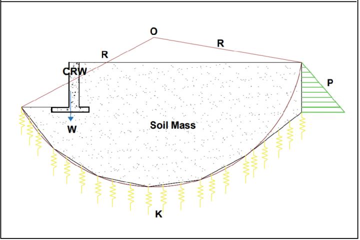
Where,
W:SelfWeightofCRW R:RadiusofSlipCircle
O:CenterofSlipCircle
International Research Journal of Engineering and Technology (IRJET) e-ISSN: 2395-0056
Volume: 11 Issue: 07 | July 2024 www.irjet.net p-ISSN: 2395-0072
P: Horizontal Pressure Applied on CRW with SSI consideration
K:ElasticSpringConstant
5. Results
The current project work is to study the effect of SSI on Cantileverretainingwallasperflowofprojectmentionedin thepreviouschapter.Profilesofcantileverretainingwalland parameters considered for the analysis of cantilever retaining wall with SSI as discussed in previous chapter. Cantilever retaining wall with different geometry and heights are designed governed by stability criteria dimensionsofcantileverretainingwallforvariousHeights are calculated using worksheet. Which are separately developed for design of cantilever retaining wall with considering horizontal backfill as a loading case (details givenasperappendixA).Asperflowofproposedstudytwo earthquake sample cases are considered. The various Heights with different geometry with and without consideration of soil structure interaction along with different earthquakecasesaresolvedusing finite element package of ANSYS. Maximum and minimum of the deformationand stressesobtainedfor eachcase,the nondimensional variations are plotted and discussed in the currentchapter.
5.1ParameterConsideredforResearchWork
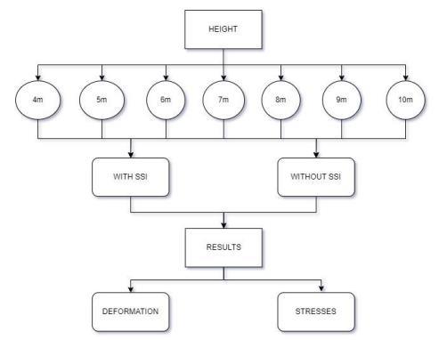
As mentioned in figure. 5.1 Various height of cantilever retaining wall are considered for analysis. For each case maximum deformation and maximum stresses (Tensile stresses)andminimumstresses(Compressivestresses)with and without soil structure interaction are obtained. The results obtained from the finite element analysis are tabulatedintablenumberA.1,A.2,A.3andA.4etc.givenin AppendixA.
5.2Variationofcross-sectionareaofCRWwithHeights
As mentioned, worksheets are developed for design of cantilever retaining wall using stability criteria. It is observed that (appendix A) stability against sliding is governingstabilitycriteriafordesignofcantileverretaining wall.Variationofcross-sectionareaofCRWaspervarious HeightscanbeobservedfromthePlotG1andfordifferent profiletwodifferenttermsaredefinedforthegeneralizing theresultsareasfollows.CantileverTrainingwallwith4m height is considered as a reference case and the term are definedwithreferenceofcaseconsidered.Theheightratio (Hr)isdefinedastheratioofheightofcantileverretaining wall to the ratio of height of cantilever retaining wall consideredasareferencecase.Cross-sectionarearatioAris definedasCross-sectionareaofcantileverretainingwallto the Cross-section area of cantilever retaining wall of referencecase
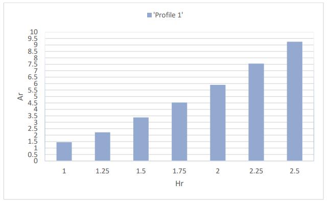
Graph G1: Variation of Area ratio (Ar) against Height ratio (Hr) of CRW
ForPlotG1showsthat,thecolumnsofchartareincreasing inuniformorder.
From plot G1 as the Hr increases Ar also increases simultaneously.
5.3VariationofdeformationpercentageofCRWconsidering SSIwithheightratio
The variation of the Deformation percentage of cantilever retainingwallswithandwithoutsoilstructureinteraction areconsidered&plottedagainstHr(Asmentionedabove) referringtotableno.3(AppendixA)TheDeformationsare obtainedasperconsideredloadingcase,onlyretainingwall andretainingwallwithsoilmass(consideringsoilstructure interaction).AreanalyzedusingFEMpackageaspercases mentionedinthefig.5.1.
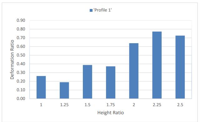
Graph G2: Variation to Deformation percentage of CRW with SSI considering against Height ratio (Hr)
PlotG2showsthat,allthetwoprofileshowingvariationsin deformation percentage compare with CRW without SSI. Consideringonlystructureandwithsoilmass.
Followingobservationsarenoted,Fromaboveplotprofile, showing variation of deformation percentage which is substantially reduced as compared to without SSI. The deformation percentage including all height is only 0.9 percentage as compared to without SSI (that is 99.1 percentage reduction is observed.) For Profile shows variation of deformation percentage increases up to maximum value that is 0.8 percentage. There after deformationpercentageuniformuptoHr.1.75.Afterwards the variation in Deformation percentage is abruptly increases. For Profile show Maximum deformation percentageatHr2.5.
5.4 Variation of maximum Stress percentage of CRW consideringSSIwithheightratio
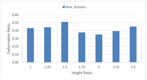
The variation of the Maximum Stresses percentage of cantilever retaining with and without soil structure interaction are considered & plotted against Hr (as mentionedabove)referringtotableno.4(AppendixA)The MaximumStressesareobtainedasperconsideredvarious heightcase,onlyretainingwallandretainingwallwithsoil mass(consideringsoilstructureinteraction).Areanalyzed usingFEMpackageaspercasesmentionedinthefig.5.1.
Followingobservationsarenoted,
2395-0072
Plot G6 shows that, all the height showing variations in MaximumStressespercentagecomparewithCRWwithout SSI. Considering only structure (excluding soil mass) and withsoilmass.
From above plot profile, showing variation of Maximum Stresses percentage which are substantially reduced as comparedtowithoutSSI.ThemaximumStressespercentage includingallprofileisonly0.51percentageascomparedto withoutSSI(thatis99.49percentagereductionisobserved.)
1. For Profile shows variation of Maximum Stresses percentage increases up to maximum value that is, 0.51percentage.ThereafterMaximumstressespercentage decreasesuptoHr1.5.Afterwardsthevariationinmaximum stressespercentagesarenotmuchsignificant.
5.5VariationofminimumStresspercentageofCRWasper dynamicloading(Kobe)consideringSSIwithheightratiofor differenttypes
The variation of the minimum Stresses percentage of cantileverretainingwallasperdynamicloading(Kobe)with and without soil structure interaction are considered & plottedagainstHr(asmentionedabove)referringtotable no.8(AppendixA)TheminimumStressesareobtainedas perconsidereddynamicloadingcase,onlyretainingwalland retaining wall with soil mass (considering soil structure interaction).AreanalyzedusingFEMpackageaspercases mentionedinthefig.5.1.
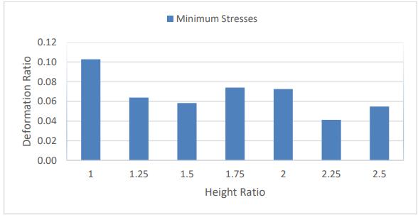
Graph G4: Variation to Minimum stress percentage of CRW with SSI considering against Height ratio (Hr)
Plot G4 shows that, all profiles are showing variations in minimumStressespercentagecomparewithCRWwithout SSI. Considering only structure (excluding soil mass) and with soil mass. Following observations are noted, From aboveplotprofile,showingvariationofminimumStresses percentagewhicharesubstantiallyreducedascomparedto without SSI. The variation of compressive stresses are practicallynotdifferforallprofileconsidereffectofSSI.The rangeofpercentagestressremainsin0.04to0.1%thatitself indicate the wall without considering SSI having reserve International Research Journal of Engineering and Technology (IRJET) e-ISSN: 2395-0056 Volume: 11 Issue: 07 | July 2024 www.irjet.net
International Research Journal of Engineering and Technology (IRJET) e-ISSN: 2395-0056
Volume: 11 Issue: 07 | July 2024 www.irjet.net p-ISSN: 2395-0072
strengthwhichincreasesalmost99.09withconsiderationof SSI.Thevariationshoesnetchangeinprofiledoesnotaffect minimuminducestresses.
ThestudyonSoil-Structure Interaction(SSI) inCantilever Retaining Walls (CRWs) reveals that including SSI in the analysissignificantlyimpactsthestructuralperformanceof CRWs. The cross-sectional area of the walls increases substantially with height. When SSI is considered, deformationdecreasesmarkedly,showingareductionofup to0.9%forlowerheightratiosandapproachingunreformed conditions at higher ratios. Maximum stresses are also reduced by up to 0.51%, and minimum stresses by 0.1%, withhigherheightratiosleadingtonegligiblestresslevels compared to models without SSI. Overall, the interaction betweenthesoilmassandtheretainingwallplaysacrucial role in minimizing deformation and stress, enhancing the stability and efficiency of the structure across varying heights.
[1] Sunil Gupta, Tsung-Wu Lin, Joseph Penzien, ChanShioungYeh(1980),“HybridModellingofSoil-Structure Interaction”,EarthquakeEngineeringResearchCenter University of California, Richmond Field Station 47th andHoffmanBlvd.Richmond,California94804,REPORT NO.UCB/EERC-80/09MAY1980
[2] Robert M. Ebeling (1990) “Review of finite element proceduresforearthretainingstructure”,Information technology Laboratory, 3909 Halls Ferry Road Vicksburg,MS39180-6199,paperITL-90-5.
[3] TimothyD.Stark,StevenM.Fitzwilliam,JoseiphJ.Vettel, Robert M. Ebeling (1991) “Soil Structure Interaction ParametersforSilts”,TechnicalReportITL-91-2.
[4] T.Kupsmy,MarkA.Zarco(1994)“User'sGuideforthe Incremental Construction, Soil Structure Interaction Program SOILSTRUCT with Far-Field Boundary Elements”,CharlesViaDepartmentofCivilEngineering Vginia Polyconic InfectandStateUnfreetyBlackiuurg, VA24061,TechnicalReportITL-94-2.
[5] Mete Oner, WilliamP.Dawkins(1997)“Soil-Structure InteractionEffectsinFloodwall”,Professors,Schoolof CivilEngineering,OklahomaStateUniversity,Stillwater, OK.www.ejge.com/1997/Ppr9707/Ppr9707.htm
[6] EduardoKausel(2010),”Earlyhistoryofsoil–structure interaction”, Department of Civil and Environmental Engineering, Massachusetts Institute of Technology, Room1-271,Cambridge,MA02139,USA.
[7] Dr. S. A. Halkude1, Mr. M. G. Kalyanshetti2, Mr. S. H. Kalyani3 (2014),” Soil Structure Interaction Effect on SeismicResponseofR.C.FrameswithIsolatedFooting”, Civil Engg. Dept. Walchand Institute of Technology, Solapur,SolapurUniversity,India.
[8] K.Senthil,M.A.Iqbal&AmitKumar(2014)Behaviorof cantileverandcounterfortretainingwallssubjectedto lateral earth pressure, International Journal Engineering, 8:2, 167-181, DOI: 10.1179/1938636213Z.00000000075Bahadure, Vrushali,andR.V.R.K.Prasad."Comparisonbetween designandanalysisofvariousconfigurationofindustrial sheds–."Internationaljournalofengineeringresearch andapplications3,no.1(2013)
[9] [9] Dr. P. P. Tapkire (2015),” Optimization of gravity retaining wall profile by introducing cavity”, Head of DepartmentofCivil Engineering ofSinhgadCollegeof Engineering, Solapur, Maharashtra, India (e-mail: pptapkire.nbnscoe@gmail.com).
[10] Ms. Patil Swapnal V. (2015), “Effect of Soil Structure InteractiononGravityDam”,AssistantProfessor,Dept. ofCivilEngg.,JSPM‟sImperialCollegeofEngineering& Research,Pune.
[11] Snehal R. Lahande(2016), “Analytical Study Of Cantilever Retaining Wall Including Effect Of Soil StructureInteraction.”,AssistantProfessor,Department Of Civil Engineering, New Horizon College Of Engineering,Karnataka,India.
[12] EkoTavipMaryanto,RezzaRuzuqi,VictorDannyWaas (2021).StrengthAnalysisofSoilRetainingWallUsing Numerical Method of Manokwari Landfill. Civil Engineering and Architecture, 9(3), 682-689. DOI: 10.13189/cea.2021.090311


Karan K. Gaidhankar
B.E.(Civil),MTech(Civil-Structure) (pursuing)ResearchScholaratN.B. Navale Sinhgad College of Engineering,Solapur,Maharashtra, India
Dr Pradeep P. Tapkire
Working as Head of Department, Civil Engineering, N B Navale Sinhgad College of Engineering, Solapur, Maharashtra, India
Graduatedincivilengineeringand did masters in structure from ShivajiUniversity,Ph.D.fromS.P. Pune University and having
International Research Journal of Engineering and Technology (IRJET) e-ISSN: 2395-0056
Volume: 11 Issue: 07 | July 2024 www.irjet.net p-ISSN: 2395-0072
experienceofmorethan18years inteachingaswell asinindustry. PG recognized teacher of Solapur University. Has selected as Board of Study Member for Solapur University,Solapur.Guided22PG studentsand16areworkingunder theguidance.HandledIITMCband radar installation project as structural and execution expert. Nominatedasmemberfordistance learning syllabus formation committee IGNOU, Delhi. Also worked as committee member to identify centers for IGNOU for distance learning courses. Receivedappreciationawardfrom ULTRATECH, Cement Solapur for contributioninM-sandProject.

Mr. Atul S. Chandanshive
Working as Lecturer in, Civil Engineering, Solapur Education Society’s Polytechnic, Solapur, Maharashtra, India. Graduated in civil engineering and did masters in structure from Solapur University,andhavingexperience ofmorethan4yearsinteachingas wellasinindustry