
International Research Journal of Engineering and Technology (IRJET) e-ISSN:2395-0056
Volume: 11 Issue: 07 | July 2024 www.irjet.net p-ISSN:2395-0072

International Research Journal of Engineering and Technology (IRJET) e-ISSN:2395-0056
Volume: 11 Issue: 07 | July 2024 www.irjet.net p-ISSN:2395-0072
Onkar Rathod #1
Prof. K.S. Bhosale #2
Prof. S.B. Tanawade #3
#1 PG Students, Structural Engineering Department, NBNSCOE, Solapur
#2 Assistant Professor, Civil Department, SVERI’s College of engineering, Pandharpur
#3 Assistant Professor, Civil Engineering Department, NBNSCOE, Solapur
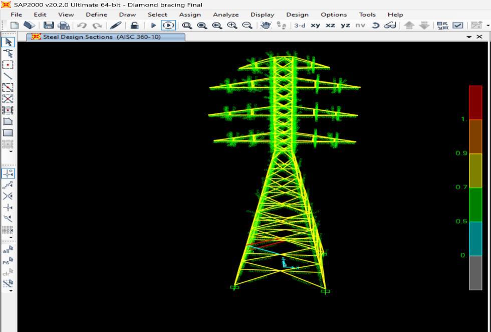
Abstract As the demand for electricity continues to rise, the cost-effective design of transmission line towers becomes increasingly important. These towers, which can account for a significant portion of the transmission line's cost, offer opportunities for optimization through exploring different lightweight configurations. This study aims to identify the most economical tower section and configuration adhering to Indian Standard IS-800. The analysis is conducted using SAP2000 software,comparingvariousbracingpatternsandtheirimpactonthetower'sprogressivecollapsebehaviour.Astandard220 kVdouble-circuittransmissionlinetowerwillserveasthecasestudy,modelledandanalysedwithinSAP2000.Thetowerwill behavingaheightof40metersandasquarebasewidthof11.5meters.Tofacilitatefabrication,thememberswillbegrouped. Steel optimization will be performed to determine the most suitable and cost-effective cross-sections. The Diamond bracing, Double bracing and Knee bracing Transmission tower will be subjected to various loads, including wind, earthquake, and its own deadweight.All analysed towers will be evaluated for both gravity andlateral loads(asperIS:875(part-III)).The final reporthaspresentedacomparativeanalysisbasedonfactorssuchasbaseshear,self-weight,modaltimeperiod,modalmass participation,andoveralltowerweight.
Keywords: TransmissionLineTower,ResponseSpectrum,timehistoryEarthquakeLoading,Loading,WindLoading.
1.1
The growing need for electricity can be met more efficiently by developing lighter designs for transmission line towers. Choosing the best configuration, along with the right bracing system, height, cross-arm type, and other parameters, plays a crucialroleincreatingacost-effectivetransmissionlinetowerdesign.
Transmission line towers are vital infrastructure, essential for delivering electricity to various regions. This has led to an increaseinpowerstationconstructionandthesubsequentexpansionoftransmissionlinesfromgeneratingstationstoareas whereelectricityisneeded.Transmissionlinesmustbestableandmeticulouslydesignedtowithstandnaturaldisasters.They mustalsoadheretonationalandinternationalstandards.
Planninganddesigningatransmissionlineinvolvesmeetingseveralstructuralandelectricalrequirements.Fromanelectrical standpoint, the most importantfactor isinsulationand maintainingsafeclearances between power-carrying conductors and theground.Theconductorcross-section,spacingbetweenconductors,andgroundwireplacementrelativetoconductorswill determinethedesignoftowersandfoundations.
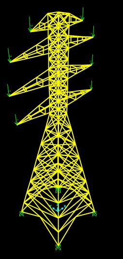
Transmission towers are modelled using various bracing patterns. Axial forces, deflections, and the tower's weight vary depending on the bracing pattern. Specific bracing patterns can help reduce the tower's weight. The main components of a transmissionlineincludeconductors, ground wires, insulation,towers,and foundations.Most ofthetime,transmissionlines aredesignedtowithstandwindandiceloadsinthetransversedirection.
International Research Journal of Engineering and Technology (IRJET) e-ISSN:2395-0056
Volume: 11 Issue: 07 | July 2024 www.irjet.net
Important aspects of constructing a transmission tower:
Table 1.1. Aspects of constructing a transmission tower Sr.
1.2 Types of Transmission Towers
A. TypethetypeoftransmissiontowerbasedontheirAngelofdeviationclassifiedAreclassifiedbelow
Table 1.2. Type transmission tower based on their Angel of deviation
Sr.No. TypeofTower AngleofDeviation
1. SuspensionTower
2. SmallangleTower
3. MediumangleTower
4. Largeangle&dead-endTower
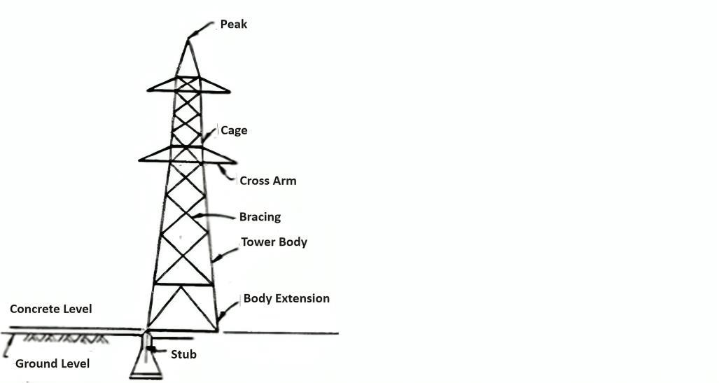
1.3 Components of transmission tower:
Transmissiontowerconsistsoffollowingparts
A. Peak: ItSupportsgroundwire.
B. Cage: InbetweenPeakandtheTowerbody.
C. Cross arm: ItSupportstheConductors.
D. Bracing: Toresistthelateralloads.
E. Tower Body: MainportionwhichconnectCageandFoundation.
F. Body Extension: Formoreclearance.
G. Stub: Itprojectstowerbodyintothefoundations.
Upto2Degrees
Upto15Degrees
Upto30Degrees
Upto60Degrees&DeadEnd
International Research Journal of Engineering and Technology (IRJET) e-ISSN:2395-0056
Volume: 11 Issue: 07 | July 2024 www.irjet.net p-ISSN:2395-0072
2.1 Introduction
A significant body of research has investigated on Transmission Tower. This review synthesizes this scholarship, identifying
centralthemes,methodologies,anddebates.
2.2 literature review
Balaji Patil, K. S. Upase (2020) [5] – studiedanalysisanddesign of transmission tower by using different typesof bracing. Author concluded that warren type bracings are not structurally stable as compare to two other types of bracing single web horizontaltypebracingandsinglewebdiagonalbracing.Singlewebhorizontaltypebracingsarestructurallysafeascompare towarrentypeandsinglewebdiagonaltypebracings.Singlewebdiagonaltypebracingtransmissiontowerisfailedatbottom legforwindspeed47m/s.
Tanvi G. Londhe (2018)[1] – studied the comparative study of different types of bracing of transmission tower by using SAP2000. Author concluded that the base reaction for single web horizontal type bracing is maximum while for single type bracingisminimum.Thedisplacementvalueishigherforsinglewebdiagonaltypebracingwhile,forwarrentypebracinghas lowervalue.Thisimpliesthatsinglewebdiagonaltypetowerbehavesmorerigidlythanothertypesoftowers.Theweightof thesinglebracingtowerislessascomparedtootherthreetypeofbracingtower.
CH. Harshini, K. Sindhu Rani (2018)[6] – concludedthatthedisplacementvaluesarequitehigherintheSTAAD-Proresult thantheETABresult.ThequantityofthesteelrequiredishigherintheSTAADresult.Transmissiontowerwithsamebracing canbeusedatthesetwodifferentwindzoneswithsameseismiczonebyusingdifferentsteelmembersatdifferentphasesof thetransmissiontoweraccordingtheeffectoftheloadonthespecificlocationmembers.In Staadproself-weightofstructure isconsideredasfactor1.Etabself-weightfactoris1.1thatmeans10%ofself-weightconsiderationismoreinEtabs.
Heera Lal Bhardwaj, Ajit Ajit, Yogesh Kaushik (2015)[7] – studiedthatanalysisanddesignoftransmissiontowerbyusing STAAD-Proandverticalconfiguredself-supportingtowerexhibitsasavingof2.65%intheweightofstructuralsteel.Butitis
International Research Journal of Engineering and Technology (IRJET) e-ISSN:2395-0056
Volume: 11 Issue: 07 | July 2024 www.irjet.net p-ISSN:2395-0072
tobenotedthatlegmembersofverticalconfiguredtowerHTsteelsectionsarerequiredtosustaintheexternalloads.Onthe otherhand,alllegmembersofthehorizontalconfiguredtowerrequiredonlyMSsectiontosustaintheexternalloadsbyusing STAAD-Pro.
2.3 Summary Of Literature Review
The researchers have been analyzing various structures using different bracing. Several investigators studied the influence flexibilityoftransmissionlinetower.Theyperformedthestudiesbychangingvarioustypeofbracingparametersoftowerand structure
1. To find the most cost-effective and stable design for a transmission line tower. We'll achieve this by exploring different arrangementsofbracingpatterns.
2. TostudythebehaviorofKnee,Dimond&DoublebracinginDifferentEarthquakezone(III,IV&V).
4. Theoretical Formation
4.1 Seismic Base Shear
According to IS 1893 (Part-I): 2002, Clause 7.5.3 the total design lateral force or design seismic base shear (VB) along any principaldirectionisdeterminedby,
Where,
Ah isthedesignhorizontalaccelerationspectrum
Wistheseismicweightofbuilding
4.2 Design Horizontal seismic coefficient
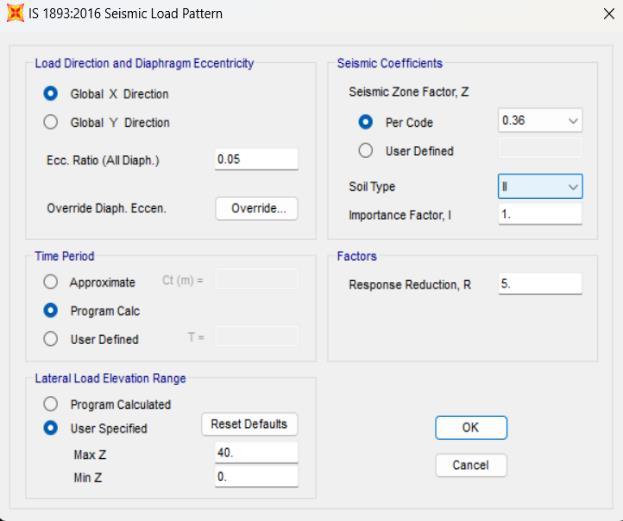
Forthepurposeofdeterminingthedesignseismicforces,thecountry(India)isclassifiedintofourseismiczones(II,III,IV,and V).Previously,there werefivezones, ofwhichZoneIandIIare merged intoZone IIinfifth revision ofcode.According toIS 1893: 2016 (Part 1), Clause6.4.2 Design Horizontal Seismic Forces Coefficient Ah for a structure shall be determined by followingexpression.
Table 4.1 Seismic Zones of India
Indiahasbeendividedintofourseismiczones.ZoneIIandZoneIIIaremajorzonescoveringmorepercentageoflandareain India. Eastern India has higher seismic intensity. It fails under zone V. North-East India falls under zone IV. Geographical statistics of India show that almost 54 % of the land isvulnerable to earthquakes. Table 3.1 & Fig.3.2 shows various seismic zonesofIndiawithtentativepercentageoflandarea.
I =Importancefactorisusedtoobtainthedesignseismicforcedependingonthefunctionaluseofthestructure,characterized byhazardousconsequencesofitsfailure,it’spost-
Earthquakefunctionalneed,historicvalue,oreconomicimportance(IS1893-2016cl.no.6.4.2/table6/pg.no.18)
International Research Journal of Engineering and Technology (IRJET) e-ISSN:2395-0056
Volume: 11 Issue: 07 | July 2024 www.irjet.net p-ISSN:2395-0072
R = Response reduction factor depending on the perceived seismic damage performance of the structure characterized by ductileorbrittledeformationswhichisshowninTable3.2((IS1893-2016cl.no.6.4.2/Table7/pg.no.23).
Sa/g = Average response acceleration coefficient (dimensionless value). The value of Sa/g is obtained from fig.3.3 from IS: 1893(Part1):2016.
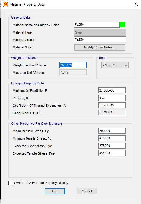
Table No 4.2: Detail Features of Tower Structure Sr. No
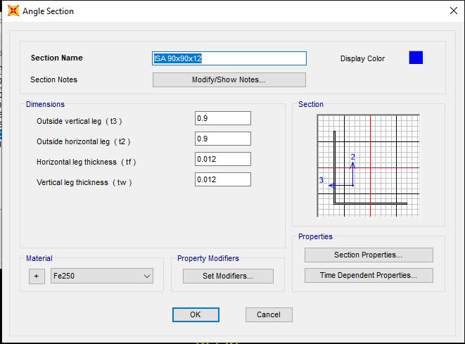
1 MaterialUsed SteelGradeFe-250
2 Totalheightoftower 40m
3 Unitweightofsteel 78.50KN/m3
4 PoissonRatio
5 CodeOfPracticeAdopted
0.2-ConcreteAnd0.15-Steel
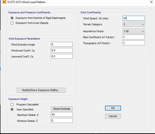
IS800:2007,IS1893:2016 IS875-part-III
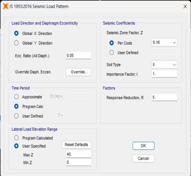
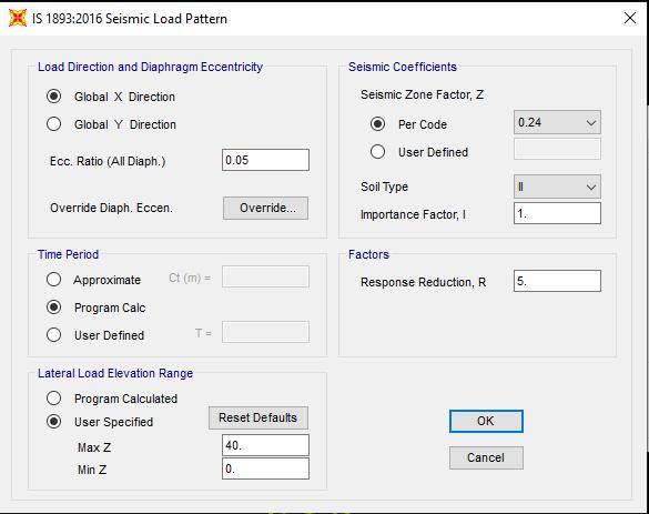
6 SeismicZoneforIS1893:2016 II,III,&IV.
7 ImportanceFactor 1
8 ResponseReductionFactor 5
9 FoundationSoil Medium
10 LiveLoad 7KN/M2
11 EarthquakeLoad AsPerIS1893-2016
4.3 Different bracing pattern
A. Double Bracing Tower Structure
International Research Journal of Engineering and Technology (IRJET) e-ISSN:2395-0056
Volume: 11 Issue: 07 | July 2024 www.irjet.net p-ISSN:2395-0072
International Research Journal of Engineering and Technology (IRJET) e-ISSN:2395-0056
Volume: 11 Issue: 07 | July 2024 www.irjet.net p-ISSN:2395-0072
Earthquake Load Define Zone III F. Earthquake Load Define Zone IV
G.Earthquake Load Define Zone V H. Wind Load Define
International Research Journal of Engineering and Technology (IRJET) e-ISSN:2395-0056
Volume: 11 Issue: 07 | July 2024 www.irjet.net p-ISSN:2395-0072
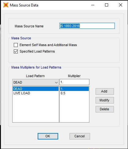
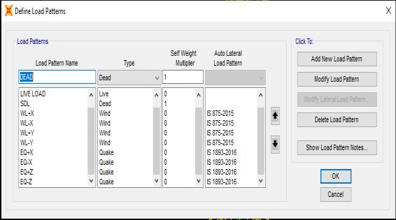
4.4 Types of Loads
Unlessotherwisespecified,allloadslisted,shallbeconsideredindesignfortheIndianCodefollowingloadcombinationsshall beconsidered.
Loadcase
1) DL:Deadload
2) LL:Liveload
3) EQ:Earthquakeload
4) WL: WindLoad
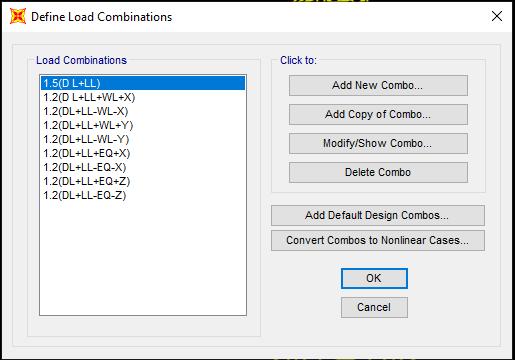
4.5 Load combination
1. 1.5DL+1.5LL
1.2DL+1.2LL+1.2EX
1.2DL+1.2LL-1.2EX
1.2DL+1.2LL+1.2EY
2024, IRJET | Impact Factor value: 8.226 | ISO 9001:2008
Volume: 11 Issue: 07 | July 2024 www.irjet.net p-ISSN:2395-0072
9. 1.2DL+1.2LL-1.2WLY
10. (0.9DL±1.5EQ)
5. RESULTS AND DISCUSSIONS
Based on the work as mentioned in earlier chapters the results are presented below:
5.1 Base Shear Results of Diamond Bracing
Table 5.1.1 Base Shear Transmission Line Tower Diamond Bracing response spectrum method of Earthquake Zone III.
TABLE: AutoSeismic-IS1893:2016
Table 5.1.2 Base Shear Transmission Line Tower Diamond Bracing response spectrum method of
TABLE: AutoSeismic-IS1893:2016
Table 5.1.3 Base Shear Transmission Line Tower Diamond Bracing response spectrum method of
TABLE: AutoSeismic-IS1893:2016
Volume: 11 Issue: 07 | July 2024 www.irjet.net
Table 5.2.1 Base Shear Transmission Line Tower double
TABLE: AutoSeismic-IS1893:2016
Table 5.2.2 Base Shear Transmission Line Tower double Bracing response spectrum method of Earthquake Zone IV.
TABLE: AutoSeismic-IS1893:2016
5.2.3 Base Shear Transmission Line Tower double Bracing response spectrum method of Earthquake Zone V.
TABLE: AutoSeismic-IS1893:2016
Volume: 11 Issue: 07 | July 2024 www.irjet.net p-ISSN:2395-0072
Table 5.3.1 Base Shear Transmission Line Tower knee Bracing response
TABLE: AutoSeismic-IS1893:2016
Table 5.3.2 Base Shear Transmission Line Tower knee Bracing response spectrum method Earthquake Zone IV.
TABLE: AutoSeismic-IS1893:2016
Table 5.3.3 Base Shear Transmission Line Tower knee Bracing response spectrum method Earth. Zone V.
TABLE: AutoSeismic-IS1893:2016
International Research Journal of Engineering and Technology (IRJET) e-ISSN:2395-0056
Volume: 11 Issue: 07 | July 2024 www.irjet.net p-ISSN:2395-0072
Graph5.1baseshearvs.bracing(diamond,doubleandknee)ofearthquake ZoneIII.
Graph5.2baseshearvs.bracing(diamond,doubleandknee)ofearthquake ZoneIV.

Graph5.3baseshearvs.bracing(diamond,doubleandknee)ofearthquake Zone
International Research Journal of Engineering and Technology (IRJET) e-ISSN:2395-0056
Volume: 11 Issue: 07 | July 2024 www.irjet.net p-ISSN:2395-0072
6. Conclusion
Inthepresentstudy,RelativeAnalysisoftransmissionslinetowerusingdifferentbracingpatterninstructurewithdifferent seismiczone III,ZoneIV&ZoneV.
ThestructuresareanalysesforearthquakezoneIII,ZoneIV&VwithmediumsoilandResultsCompare.It hasbeenmadeonbaseshear,theanalysisresultsfollowingconclusionsaredrawn.
1. TheBaseShearofDiamondBracing&DoubleDiagonalBracinginZoneIII iscloselyspaced,WhileBaseshearofDiamond Bracingisincreased4.37timesascomparetokneebracingsystem.
2. TheBaseShearofallthreebracinginZoneIII,IV,&Visincreasedinthesameratio1:1.17:3.72.
1. RajasthanRajyaVidyutprasaranNigamltd.“ConstructionManualfortransmissionlines”July2007,Jaipur.
2. TanviG.Londhe,Prof.M.S.Kakamare(2020)“ReviewPaperonComparativeStudyofDynamicAnalysisofTransmission Towers”.InternationalResearchJournalofEngineeringandTechnology(IRJET)e-ISSN:2395-0056Volume:05Issue:08| Aug2018www.irjet.netp-ISSN:2395-0072.
3. Dr.S.A.Halkude,Mr.P.P.Ankad(2014)“AnalysisandDesignofTransmissionLine Tower220kV:AParametric Study”. InternationalJournalofEngineeringResearch&Technology(IJERT)Vol.3Issue8,August–2014.
4. CH. Harshini, K. Sindhu Rani (2018) “A Comparative Study of Wind Analysis on 220KV Transmission Line Tower in STAAD-Pro&E-Tabs”.InternationalJournalofScienceandResearch(IJSR)Volume7Issue6,June2018.
Code Used
1. IS13920,”Ductiledetailingofconcretestructuresubjectedtoseismicforcescodeofpractice”,1993.
2. IS875(part1-5)-codeofpracticeforstructuralsafetyofBuildingloadingstandards.
3. IS 875, “Code of practice for design loads (other than earthquake) for building and structures - Part 2: Imposed loads”, BureauofIndianStandards,NewDelhi,1987.
4. IS 456, “Indian Standard Code of Practice for Plain and Reinforced Concrete”, Bureau of Indian Standards, New Delhi, 2000.