
International Research Journal of Engineering and Technology (IRJET) e-ISSN: 2395-0056
Volume: 11 Issue: 08 | August 2024 www.irjet.net p-ISSN: 2395-0072

International Research Journal of Engineering and Technology (IRJET) e-ISSN: 2395-0056
Volume: 11 Issue: 08 | August 2024 www.irjet.net p-ISSN: 2395-0072
Vishal Vishwanath Ballal 1 , Dr. A.B. Kolekar2 , Mr. G. R. Shinde3
1M. Tech Student, Department of Technology, Shivaji University, Kolhapur, Maharashtra
2 Professor, Department of Technology, Shivaji University, Kolhapur, Maharashtra
3Assistant Professor, Department of Technology, Shivaji University, Kolhapur, Maharashtra
Abstract - Welding is a fabrication or sculptural process that joins materials, usually metals or thermoplastics, by causing fusion, which is distinct from lower temperature metal-joining techniques such as brazing and soldering, which do not melt the base metal. In addition to melting the base metal, a filler material is often added to the joint to form a pool of molten material (the weld pool) that cools to form a joint that can be as strong, or even stronger, thanthe base material. Pressure may also be used in conjunction with heat, or by itself, to produce a weld. All the welding machines are 1phase and 2phase in nature and only one user can work on one machine, no other one user can work on same machine. If we use another holder for welding then we should use another welding machine, so it will increase cost of machine, it takes some space, energy use, so, by using three phase welding machine we can overcome this problem. In three phase welding machine we use three holders at a time for low and medium work and for heavy work we can use two holders at a time.
Key Words: Welding, Welding Transformer , winding, electrical energy , Frequency
Welding isa fabrication or sculptural process that joins materials, usually metals or thermoplastics, by causing fusion, which is distinctfrom lower temperaturemetaljoiningtechniquessuchasbrazingandsoldering,whichdo notmeltthebasemetal.Althoughlesscommon,thereare alsosolid-stateweldingprocessessuchasfrictionwelding or shielded active gas welding in which metal does not melt.
Someofthebest-knownweldingmethodsinclude:
Shieldedmetalarcwelding(SMAW)–alsoknownas"stick weldingorelectricwelding",usesanelectrodethathas fluxaroundittoprotecttheweldpuddle.Theelectrode holderholdsthe electrode as it slowly melts away. Slag protects the weld puddle from atmospheric contamination.
i) Gastungstenarcwelding(GTAW)–alsoknownasTIG (tungsten,inertgas),usesanon-consumabletungsten
electrode to produce the weld. The weld area is protected fromatmospheric contamination by an inert shielding gas such asargonorhelium.
ii) Gasmetalarcwelding(GMAW)–commonlytermed MIG (metal,inertgas),usesa wirefeedinggunthat feedswireatanadjustablespeedandflowsanargonbased shielding gas or a mix of argon and carbon dioxide (CO2) over the weld puddle to protect it fromatmosphericcontamination.
iii) Flux-coredarcwelding(FCAW)–almostidenticalto MIG welding except it uses a special tubular wire filled with flux; it can be used with or without shieldinggas,dependingonthefiller.
iv) Submerged arc welding (SAW) – uses an automaticallyfedconsumableelectrodeandablanket ofgranularfusibleflux.Themoltenweldandthearc zoneareprotectedfromatmosphericcontamination bybeing"submerged"underthefluxblanket.
v) Electroslag welding (ESW) – a highly productive, single pass welding process for thicker materials between1inch(25mm)and12inches(300mm)ina verticalorclosetoverticalposition.
Thedesignoftransformerdependsupontheratings,voltage, type, service conditions, and the relative costs of copper, iron,insulatingmaterials,labor,machineryandorganization. Weldingtransformerisessentiallyastep-downtransformer withafixedstandardprimaryinputvoltage230/250volts forsinglephaseunitsand400/440voltsfordoublephaseor threephaseunits.Thesecondaryvoltagebeing50/60to100 voltsdependingontheserviceconditionandtheworkfor whichitistobeused.
Coreframesarestandardizedtoreducethemanufacturing cost. Preliminary designs are prepared on the basis of previousexperience,withdueregardtotheeconomicaluse ofmaterials.Thus,dimensionsmayhavetobemodifiedin
International Research Journal of Engineering and Technology (IRJET) e-ISSN: 2395-0056
Volume: 11 Issue: 08 | August 2024 www.irjet.net p-ISSN: 2395-0072
ordertoavoidwastageoflargequantitiesofsheetsteelorto conformtothetransportloadinggauge.
ɸm=Mainflux.Wb.
Bm=maximumfluxdensity.Wb/m2.
ɗ =Currentdensity,amperes/m2.
Ai=netcoresection,m2.
Aw=netwindowarea,m2.
L=Corelength,m.
D=Distancebetweencorecenters,m.
d=diameterofcircumscribedcircleroundcore.
kw=Spacefactorforwindow.
f=frequencyC/S.
Et=e.m.f.perturn.Volts.
T1,T2=numberofprimaryandsecondaryturns
I1,I2=primaryandsecondarycurrents,amperes. V1,V2=primaryandsecondaryvoltage,volts.
a1,a2=primarysecondaryconductorsection,m2.
With a current density windings,thecopperareainonewindow,forathree-phase transformeris2(a1T1+a2T2)=KwAw.
Now,asa1T1=a2T2
PrimarycurrentI1=a1ɗ=Kw Awɗ/AT1
Sothatforampereturnsofprimaryorsecondary IT=I1T1=I2T2=¼KwAwɗ
Theratinginvoltampereis,
S=3V1I1, =3V1/T1=I1T1=3EtIT =34.44fBmAi1/4KwAwɗ =3.33ofAwAiBmɗ Kw….(A)
Andincaseofsingle-phasecoretypetransformer(orshell type)theactivewindowareais, (a1T1+a2T2)=KwAw.
Sothattheoutputbecomes S=2.22fAiAwBmɗ Kw….(B)
Thisbasisfordesigncanberelatedcomparativelysimplyto the emf per turn. Since the flux ɸ m determines the core section the ampere turns IT fix the total copper area, the ratio ɸ m / IT = r will be constant for a transformer of a giventype,serviceandmethodofconstruction.Theoutput inKWAperphaseis,
S=4.44fɸmT,I*10^3 =4.44(ɸm^2/r)10^3 ɸm=√(r.10^3/4.44f
SubstitutingthisvalueofɸmintheexpressionforEt, Et=4.44fɸm
=4.44f√s.√(r.10^3/4.44f) =K√s
WhereK=√(4.44fr.10^3)
This value of K depends on type, material labour, costs, factory organization, etc. the ratio r does not change with size,inarangeofKapproximatelyis
(a) Forthreephaseweldingtransformer–0.5to0.7
(b) Forsinglephaseweldingtransformers
i) Shelltype=1to1.2
ii) Coretype=0.75to0.85
Withthisaworkabledesigncannowbebuiltonabasisof experience.ChoosingBmandtheproductAiAwisknown from equation (A) or (B) Et from equation (C) and appropriatevalueofAicanbecalculatedfromEtandchosen valueofBm.Thecoreisdesignedtoconformtoastandard frame,fromwhichdandDareobtained.ThelengthLofthe windowbetweencorecircumscribingcircle.
Thenetcoreareais0.9timesthegrossareafor10percent dependonthequalityofcorematerialandwindingmaterial respectively.Generally,forweldingtransformertheBmis taken as 1 Wb/m^2 dynamo grade type laminations 1.2 Wb/m^2forcoldrollednon-grain-orientedtype.
The current density is taken in between 5 and 10 Amps/sq.mmdependingonthedutycycleforwhichitisto bedesigned.
Dutycycleismorecriterionwhichgenerallyisnottakenin toaccountwhiledesigningothertransformersbutshouldbe takenintoaccountwhiledesigningweldingtransformerviz someweldingtransformersaredesignedfor60%dutycycle, somefor35%,dutycycleorfor20%dutycycletoo.
3 ɸweldingmachine,20kva,440volt/60volt.
Theprimarycircuitwasdesigntovaryincurrentselection withouttemperingwiththecoilitself.ithasafour-stepcoil withthreeloopingfortheselectionofcurrentcapacity.
Theprimarywindingisstarconnected.Inprimarycircuitthe winding has total 175 turns for 240volts.the winding beginsatthestartpointSandwasgiven160turnswithan aluminumwireofsizegauge11.Thefirsttapwasintroduced after the first winding and was labeled A, the winding continueswithsamesizegaugeforanother5turnsbefore thesecondtaplabeledB.ThethirdtapCandthelastwinding labeledEwasgiven5turnseachwithsamesizewiregauge 11.
International Research Journal of Engineering and Technology (IRJET) e-ISSN: 2395-0056
Volume: 11 Issue: 08 | August 2024 www.irjet.net p-ISSN: 2395-0072
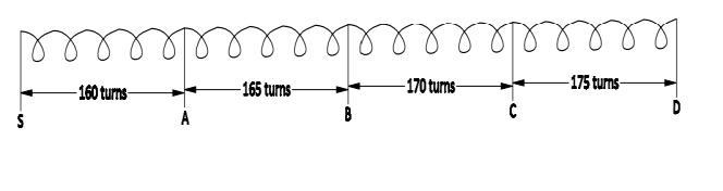
Fig.1Primarywinding
The secondary winding is star connected. In secondary circuitthewindinghastotal23turnsfor33volts.thewinding beginsatthestartpointSandendwithCanaluminumwire ofsizegauge3.
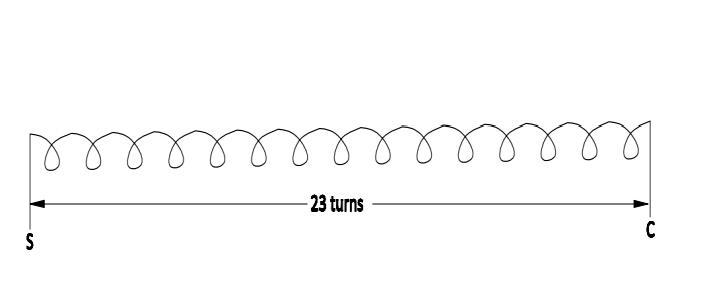
Fig.2Secondarywinding
Table1:showingtheprimaryvoltageandprimaryturn values.
Primaryvoltage(star connection) Primaryturn
240volts 160turns
245volts 165turns
250volts 170turns
260volts 175turns
Table2:showingthesecondaryvoltageandload secondaryturnvalues.
Secondaryvoltage(star connection) Secondaryturn
34volts 23turns
Table3:showingtheprimaryandsecondarycoil specificationsvalues.
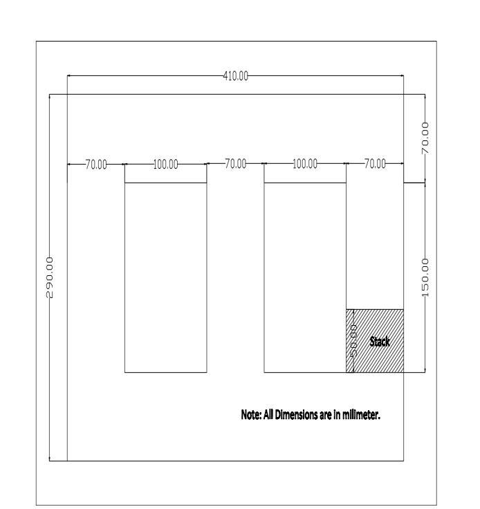
Fig.3Threephasecore
The core is made of laminations assembled to provide a continuous magnetic path with a minimum of air gap included.Thelaminationsteelhelptominimizeeddycurrent lossandthethicknessofthelaminationvariesfrom0.35mm forafrequencyof50Hz0.5mmforfrequencyof25Hz.The coresareintheformoflong strips.L’s,E’sandIshapesas shownbelow
Table4:showingthelaminatedcorestripandweight calculationvalues.
International Research Journal of Engineering and Technology (IRJET) e-ISSN: 2395-0056
Volume: 11 Issue: 08 | August 2024 www.irjet.net p-ISSN: 2395-0072
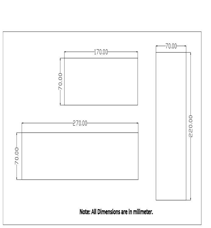
Fig.4Laminatedcore
i) Aluminum as Coil
Aluminum wire is of more advantages in winding process. It is easy to winding. It has less weight compared to copper. low tensile strength. Most advantage is, it has low cost compared to copper andeasilyavailableinmarket.Thecurrentdensity usedforaluminumwireis1.5A/sqmm.
ii) Insulators
Insulators are materials that do not conduct electricityinform. Theyare used toseparatetwo wirestoavoidpartialcontactofanyform.
Intheconstruction,thelaminatedcorewasarrangedfirstto formthethreepolesasshownbelow,
The total laminated core used for the I shaped, of size (70*220)mmis600strips,anotherIshapeofsize(70*170) is400strips,andonemoreIshapeofsize(70*270)is200 strips. Total of 1200 laminated core used in all. In the winding, theshapeofthelaminatedcore wastakenand a corewasformforthewindingofthecoil.Thenextstepwas thefixingofthecoilinthepoleandpoleandthecrossingof the top of the machine with an ‘I’ laminated core to avoid Buttjoint.Theconstructionworkisasshown.
A) Connections
The major kinds of connections that can be given to this constructioninclude.
a)star-deltaconnectionorendtostartconnection
b)star-starconnectionorstartostartconnection
c)Delta-Deltaconnectionorendtoendconnection
A transformer may be subjected to a range of tests for a varietyofpurposes, Including.
i) Routinetestsaftermanufacture
ii) Acceptancetests.Heatruns,etc.
iii) Specialized investigations on particular details of design,performanceoroperation.
TherearefollowingRoutineTestsofWeldingtransformer
i) InsulationResistanceTest
ii) OpenCircuitVoltageTest
iii) LoadCharacteristicTest
iv) ShortCircuitTest
v) HighVoltageTest
i)InsulationResistanceTest–
Theinsulationresistancebeforeandafterhighvoltagetest shall be not less than two mega ohms. The insulation resistanceshallbemeasuredwithD.C.voltageofabout500 volts applied for a sufficient time for the reading of the indicator to become practically study, such voltage being taken from an independent source or generated in the measuring instrument. This is required to ensure low leakage current to flow through the earth and safety purposes.
ii)OpenCircuitVoltageTest–
With input side connected to the rated input voltage and output side open circuited, the open circuit voltage (of secondary output) shall be measured. In normal case it should not exceed, 80 volts (R.M.S.) in special cases, it is permissiblefortheopencircuitvoltagetobeupto100volts (R.M.S.)ThepermissibletolerancefortheO.C.voltageis5%.
iii)LoadCharacteristicTest–
The transformer shall be connected to the rated input voltage. The output terminals shall be connected to the variable resistive load. The relation between the welding load voltage and the welding current within the range of welding power source shall be in accordance with the formulaU=20+0.4I,where‘U’istheloadvoltageand‘l’is theloadcurrent.
Theaccuracyofthecurrentcalibrationshouldbe+10/-20 percentuptothemaximumcontinuousweldingcurrent,and +-10%forcurrentsabove
that.Atableofweldingcurrentandweldingloadvoltagecan beasfollows-
International Research Journal of Engineering and Technology (IRJET) e-ISSN: 2395-0056
Volume: 11 Issue: 08 | August 2024 www.irjet.net p-ISSN: 2395-0072
Table5:showingtheoutputloadvoltageandloadcurrent values.
iv)ShortCircuitTest–
Steady short circuit current at any setting with in the specified range shall be not more than 200 percent of the weldingcurrentcorrespondingtothissetting.Undershort circuitconditionthevoltagebetweenoutputterminalsshall notexceed3volts.whiletakingthistestcareshallbetaken toensurethatthetestshallnottakemorethan10seconds.
v)HighVoltageTest-
Thetransformerwindingshallbecapableofwithstanding withoutbreakdownthehighvoltagetest.Thistestshallbe appliedonce&toanewmachineonly.Itshallbecarriedout at the manufacturers works and at the conclusion of the temperaturerisetest,ifconducted.
4. RESULT AND DISCUSSION
Beingavariabletransformerselectiontype,thecurrentat bothinputandoutputofthetransformerweredetermined thus;
Table6:showingtheinputandoutputvoltagevaluesfrom theweldingmachine
recordedwhenthetransformerwasconnectedtothepower supplyatzeroloadwhilethescalingfactoristheratioofthe outputvoltageandinputvoltage.Theturnfactorwasalso calculatedtodeterminetherelationshipoftheturngivento thetransformerandthescalingfactorasshownabove.
Table7:showingtheoutputloadvoltageandloadcurrent values.
Oneholder (10-gauge rod)
Thevoltagein(Vin)wasdetermineddirectlyfromthemains ofpowersupplyandrecorded.Thevoltageout(Vout)was
Twoholders (8-gaugerod)
Threeholders (10gaugerod)
Voltage 34 58 34
Current 120amp 180amp 120amp
Inthreephaseweldingmachineweusethreeholdersata time for low work. we can use two holders at a time for mediumworkandforheavywork.Also,wecanusesingle userortwousersforlow,mediumandheavywork.
There are different types of welding machines availableinmarket,like1phase,2phaseweldingmachines dependinguponcurrentratinge.g.,150-amp,200-amp, 300-amp,400-amp,500-amp,600amp.Butallmachines areavailablein1phase230voltand2phase440voltand allmachineshaveonlysingleuser.
In domestic and industry sector, welding machines perform and completes veryimportant role, there are different types of welding machines used e.g., MIG-Gas Metal Arc Welding (GMAW), TIG-Gas Tungsten Arc Welding (GTAW), Stick Shielded Metal Arc Welding (SMAW) and Flux cored Arc Welding (FCAW). All the welding machines are 1phase and2phase in nature and only one user can workon one machine, no other one usercanworkonsamemachine.Ifweuseanotherholder forweldingthenweshoulduseanotherweldingmachine, so it will increase cost ofmachine,it takes somespace, energyuse,so,byusingthreephaseweldingmachinewe can overcome this problem. In three phase welding machine we use three holders at a time for low and mediumworkandforheavyworkwecanusetwoholders ata time. Also, wecan use single user or two users for low, mediumandheavywork.
[1] Shravan C, N. Radhika, N. H. Deepak Kumar & B. Sivasailam, “A review on welding techniques: properties,characterisations and engineering application,” AdvancesinMaterialsandProcessingTechnologies, 05Mar 2023,DOI:10.1080/2374068X.2023.2186638
International Research Journal of Engineering and Technology (IRJET) e-ISSN: 2395-0056
[2]HarmishBhatt,StudyofEffectofProcessParametersof WeldingduringTIGweldingofAA7075anditsoptimization, InternationalJournalofAppliedEngineeringResearch,ISSN 0973-4562Volume13,Number12(2018)pp.10658-10663
[3] Iqbal Taufiqurrahman, Azlan Ahmad, Mazli Mustapha ,Turnad Lenggo Ginta , Luthfi Ady Farizan Haryoko and Imtiaz Ahmed Shozib, The Effect of Welding Current and Electrode Force on the Heat Input, Weld Diameter, and Physical and Mechanical Properties of SS316L/Ti6Al4V Dissimilar Resistance Spot Welding with Aluminum Interlayer,Materials 2021, 14(5),1129;https://doi.org/10.33 90/ma14051129
Volume: 11 Issue: 08 | August 2024 www.irjet.net p-ISSN: 2395-0072 © 2024, IRJET | Impact Factor value: 8.315 | ISO 9001:2008