
International Research Journal of Engineering and Technology (IRJET) e-ISSN: 2395-0056
Volume: 11 Issue: 08 | Aug 2024 www.irjet.net p-ISSN: 2395-0072

International Research Journal of Engineering and Technology (IRJET) e-ISSN: 2395-0056
Volume: 11 Issue: 08 | Aug 2024 www.irjet.net p-ISSN: 2395-0072
PrashanthaNaikKP DrSGSrivani DepartmentofElectricaland ElectronicsEngineering
RVCollegeofengineering Banglore,India
DepartmentofElectricaland ElectronicsEngineering
RVCollegeofEngineering Bengaluru,India
KAkhileshReddy AshwinHN
TakumimotioncontrolPvt.Ltd Bangalore,India
Abstract This paper presents the design and development of a resolver-based Permanent Magnet Synchronous Motor (PMSM) controller for electric vehicle applications. Nowadays, internal combustion (IC) engines are increasingly being replaced by plug-in hybrid, hybrid, or electric vehicles due to their disadvantages. In electric vehicles, the system comprises various components, including the Motor Control Unit (MCU), Intelligent Vehicle Control Unit (iVCU), Battery Management System (BMS), Fault Diagnostics Unit, and PMSM. This paper focuses primarily on the Motor Control Unit, which includes the control board, gate driver board, capacitor bank, and power board. Resolvers and encoders are utilized to measure the speed, position, and direction of the motor shaft. This feedback is used to adjust the power delivered to the motor, ensuring desired operating characteristics. Resolvers are preferred over encoders for harsh environments with high temperatures or radiation. A microcontroller generates PWM pulses to drive the inverter circuit and operate the PMSM motor
Keywords PPMS motor, fly back converter, LT spice, op-amp, PMIC IC.
Electric vehicles (EVs) were first invented in the early 19th century, around the 1820s and 1830s. They became economically viable in the 1890s. Despite their potential,EVs were initiallyless popular due to higher costs, lower speed ranges, and shorter distances compared to internal combustion engines (ICEs), which dominated the 20th century [1]. By the early21stcentury,interestshiftedtowardsEVsdueto the environmental impact of ICEs, including carbon emissions,climatechange,environmentaldamage,and adverseeffectsonhumanhealth[2].
TakumimotioncontrolPvt.Ltd Bangalore,India
Since 2010, global sales of electric vehicles havesurged,reachingonemillionbySeptember2016. Bythe endof2019,there were4.8millionEVsinuse, anditwasprojectedthat10millionEVswouldbesold bythe end of2020.Thisgrowth reflectstheevolution of electric vehicles [3]-[6]. Compared to other motor types such as DC motors, synchronous motors, and induction motors, Permanent Magnet Synchronous Motors(PMSMs)offersuperiorperformance,including betterdynamicandsteady-statecharacteristics,higher efficiency, reduced size, increased torque, and higher power density. These advantages lead to smaller motor sizes and fewer torque ripples during commutation [7]-[10]. PMSMs are widely used in defense, agriculture, and everyday applicationsdue to therapiddevelopmentofpowerelectronics.
PMSMs can be controlled using two primary methods: vector control and direct torque control. Vector control involves managing and measuring the stator current vector to control motor torque by generatingexcitationandtorquecurrentsbasedonthe field-oriented principle [8]-[12]. Direct torque control directly regulates the torque [13]. In alternating current machines, such as induction or AC motors, torque creation is similar to that of direct current motors. The stator generates fields, and the rotor is not perpendicular. Field-Oriented Control (FOC) decouples flux and torque components, offering several advantages over the V/F control approach [14]-[18]:
1. Providesfulltorqueacrossawiderangeof speeds.
2. Improveddynamicperformance.
3. Effectivetransientandsteady-stateanalysis.
4. Hightorqueandlowcurrentduringstarting.
5. Enhancedefficiency.
International Research Journal of Engineering and Technology (IRJET) e-ISSN: 2395-0056
Volume: 11 Issue: 08 | Aug 2024 www.irjet.net p-ISSN: 2395-0072
6. Decouplingoftorqueandcurrent(flux) control.
7. Four-quadrantoperation.
The primary goal of the resolver is to accurately calibrate or position the rotor in a Permanent Magnet Synchronous Motor (PMSM), which is crucial for field-oriented control [19][21]. This study focuses on how the resolver influences the output voltage of the sine and cosine waves generated using the two-winding
technique [22]-[23]. The resolver's error, which affectsthe accuracyofthesineandcosinevoltage signals, can lead to decreased electromagnetic force and impact the motor current due to rotor position inaccuracies. These errors can result in increased vibration and noise in the electrical drive system. The comparative study highlights thatresolvererrorscontributetomotorvibration, and the experimental results validate the theoretical analysis of the resolver's accuracy [24]-[25].
II. PROPOSED APPROACH
A. Blockdiagram
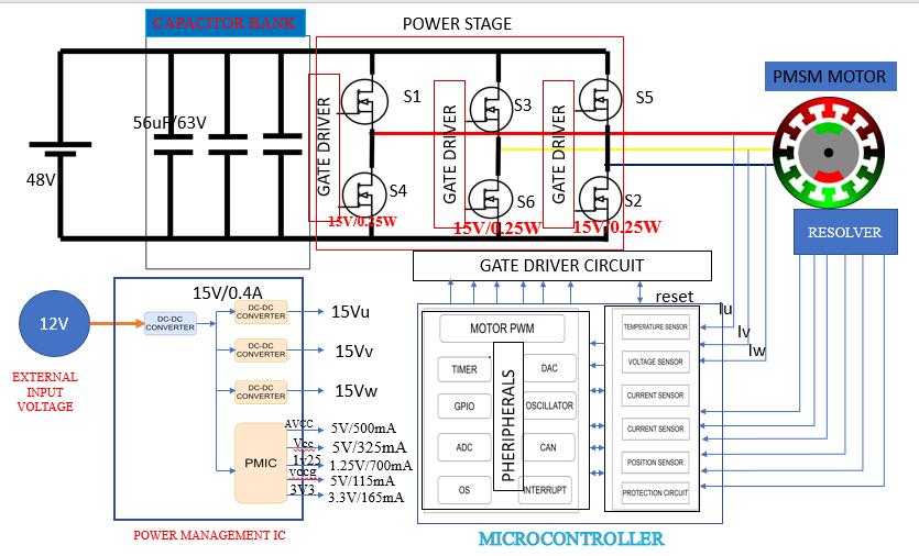
An electric vehicle's various components include the on-board charge controller, DC-DC converter, power battery pack, auxiliary battery, intelligent vehicle control unit, motor control unit, battery management system, PMSM motor, telematics, and fault diagnostics unit. We're working on the motor controller unit (MCU), which is responsible for positioning the PMSM motor controller and powering the electrical vehicle. MCU consists of the following components: control board, gate driver board, capacitor bank, and inverter circuit (power stage) board. IAUT300N10S5N015 is a MOSFET IC with a ratingof100V,300A,and1.5mOhmthatisusedonthe power stage board to convert constant DC voltage to pulsingAC,allowingthePMSMmotortowork.
The NCU18WB473F6SRB thermistor IC is used to monitor resistance to temperature at various values and to protect the MOSFET from overheating. The LT8301isa fly back power supplyIC thatcreatesand provides sufficient voltage to the gate driver IC. UCC27211andUCC27524ICscreatepulses,whichare
subsequently fed to MOSFET ICs. We employ LMV842 voltage follower ICs in the power stage to measure phase and line voltages, which have an operating voltage of 5V and clip to 5V at higher voltages. The voltage follower circuit has a high input impedance andalowoutputimpedance.
The LT8302 fly back auxiliary power supply ICs are usedtoproduceasufficientvoltageof+15Vfrom+12V for the voltage comparator or differential op-amp circuit,aswellassupplyvoltagetotheLT8301power IC. Voltage comparator ICs compare two different voltage levels given to the microcontroller. This integrated circuit protects the MCU against overcurrentandovervoltage.Themicrocontrollerruns at 3.3V and has a frequency of 240MHz. It offers two products:onewith252pinsfortwomotorcontrollers and the other with 176 pins for a single motor controller. A 144-pin microcontroller is used to operateasinglemotor.
The microprocessor generates pulses that are deliveredtothegatedrivercircuit,whichactivatesthe inverter circuit. It also includes EEPROM memory, which is used to program languages. The microcontrolleralsohasaCantransreceiver,whichis
International Research Journal of Engineering and Technology (IRJET) e-ISSN: 2395-0056
Volume: 11 Issue: 08 | Aug 2024 www.irjet.net p-ISSN: 2395-0072
used to communicate with the motor and CPU. The resolver is utilized in the PMSM motor application to detect rotor position. Resolver hardware can be thought of as two inductive position sensors that generate two sinusoidal signalsonoutput in response toa sinusoidal-shaped inputsignal. The amplitudes of the output signals fluctuate with the position of the shaft. The amplitude of one signal is proportional to the sine, whereas the other is proportional to the cosineoftheshaftangleposition.
In the power management section, the external input voltage of 12V is applied to the isolate fly back converter, whichactsasa boostconverter,converting the12Vsupplyto15V.The converter'soutputvoltage decides which circuits will be used: overcurrent amplifier, overvoltage amplifier, gate board, and power board circuit. The isolated fly back converter will receive the converter output at 15 volts. The 15V converter output voltage will be routed to two separate mosfet driver circuits, which will produce pulses independent of the inverter circuit switches. The power management integrated circuit applies a 15V input voltage from the converter output. The power management integrated circuit applies a 15V inputvoltagefromtheconverteroutput.ThePMIChas an adjustable frequency Buck/Boost pre-regulator with synchronous buck, three internal LDO watchdog timers, and a power-on reset. Its working voltage ranges between 2.8 and 36 volts. It features an adjustable synchronous buck regulator with a voltage of 1.25V and 700mA. The internal low-dropout regulators give output voltages of 5V/500mA, 5V/325mA, 5V/115mA, and 3.3V/165mA. The PMIC has a power on reset that is activated after a 15ms delay, and the microcontroller is reset using a fault flag.
B. Proposedtopology
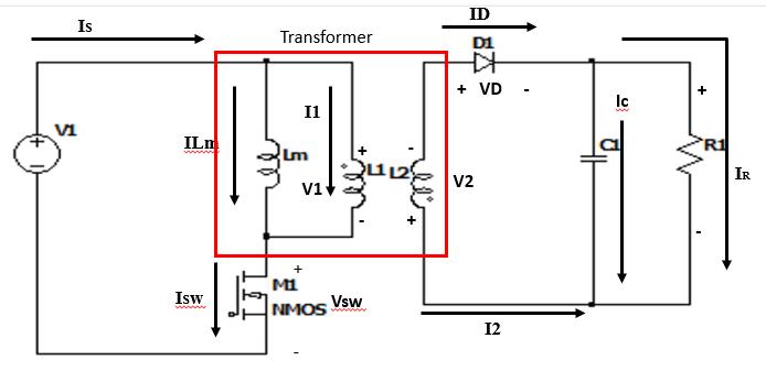
The suggested system uses a DC-DC converter that is basedonaflybackconverter.Intheproposedsystem, two fly back DC-DC converters are used. The LT8302 will convert 12V to 15V, while another converter will convert 15V to 15V. These converters function similarlytotheflybackconvertertopologydepictedin Fig2below.
The following assumptions are made for the flyback converter:
1.Theinitialcomponentsareideal,suchastheswitch anddiode.
2. The circuit is evaluated under steady-state conditions.
3. Large output capacitors prevent voltage ripples.
4.TheswitchwilloperatewithadutyratioofD,closed for DT and opened for (1-D) T.
5. Inductor current is continuous during continuous conductionmode(CCM).
Mode 1:Theflybackconverterworkssimilarlytothe Buck-Boost converter, with the only difference being voltage polarity. When the switch is closed, the secondary inductance of the transformer diode is turned off due to voltage polarity, so the current throughthediodeandthecurrentflowingthroughthe primarytransformerarebothzero.Thesupplyvoltage isdirectlyconnectedtothetransformer'smagnetizing inductance,and the inductorcharges using the supply voltage. The voltage across the diode will be less than zero, leading it to shut off. Because of the transformer's mutual inductance, the current flowing through the diode on the secondary side will be zero, resulting in a zero-primary current through the transformer.ThepowerflowispresentedinFig3.

Fig3circuitdiagramoftheFlybackconverterwhen switchisclosed
Mode 2: The energy stored in the magnetizing inductorwhentheswitchisclosed;whentheswitchis open, the current flowing through the Lm does not changedirection,sotheirvoltagepolaritychanges,and thestoredenergydissipatesthroughthetransformer's primary inductance, changing the dot polarity of the primary inductance. The current flows through the primary inductance, from undotted to dotted. The secondaryside'smutualinductancecausesthecurrent to flow from dotted to undotted. When the polarity changes or current flows from the dotted to undotted terminals, the diode turns on. The energy was transferred to the capacitor and the load resistor. In this scenario, the capacitor will store energy. Figure 4 showsthecircuitduringswitchopen.
International Research Journal of Engineering and Technology (IRJET) e-ISSN: 2395-0056
Volume: 11 Issue: 08 | Aug 2024 www.irjet.net p-ISSN: 2395-0072
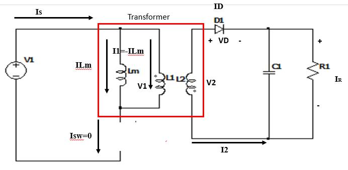
Fig4circuitdiagramwhenswitchidsopen
III. SPECIFICATION AND DESIGN OF THE PROPOSED SYSTEM
A. specificationoftheproposedsystem.
The design specification of the proposed system andrepresentedbelowintableI.
TableIspecificationoftheproposedsystem
Parameter Specification
InputVoltageRange 48VDC Speed 6000rpm
96%
SwitchingFrequency 10KHz
Motor PMSM
Rotortype Innerrotor
Auxiliarypowersupply 12VDC
B. specificationdetailsofauxillarypowersupply
Auxiliary power supply specification design details of theflybackconverterfollowbelowinTable2.
TableIIspecificationoftheFlybackconverter
Parameter Specification
InputVoltageRange 12VDC
Outputvoltage 15VDC
Outputcurrent 400mA
Efficiency 85%
Loadresistor 37.5Ohm
Topology Flybackconverter
Outputpower 6W
Referencevoltage 1VDC
a. Selectthetransformerturnsratiocalculation
Leakage voltage/Margin for transformer leakagespikes,Vleakage=24.25V
Outputdiodeforwardvoltage,Vf=0.425V ( ) (1)
Selection of turns ratio of the transformer, Nps=1
PrimaryandSecondaryturnsare,N1:N2=1:1
b. Calculation of the primary and secondary inductance
By calculating the primary and secondary inductance are used satisfy the minimum switch ON and OFF time of the switch is required, ( ) ( ) ( ) (2) ( ) ( ) ( ) ( )
Because of turns ration, Ns=1 hence the secondary inductance same as primary inductance,
c. Calculationofdutyratiofortheswitch Duty ratio of the switch for the turn time or pulsewidthoftheswitchcalculatedbelowfor theswitch ( ) ( ) (3) ( ) ( )
d. Calculationofswitchingcurrentandswitching frequency
The current flowing through the drain of the MOSFET switch which will reduces the EMI and voltage spikes of the transformer. Calculation of the switching current and switchingfrequencyareshownbelow, (4) ( ) ( )
International Research Journal of Engineering and Technology (IRJET) e-ISSN: 2395-0056
Volume: 11 Issue: 08 | Aug 2024 www.irjet.net p-ISSN: 2395-0072
( )
e. Calculation of the output diode current and reversevoltageoftheoutputdiode
The maximum current flowing through the output diode during the forward bias and maximum reverse withstand voltage for the diode during the reverse bias is calculated below,
( ) (6) ( ) (7)
f. Calculationoftheoutputcapacitor
By choosing the output capacitor to minimize the output ripple voltage of the Fly back converter by considering the increase in size andcostofalargecapacitor.Outputcapacitor calculatedfortheoutputripplelessthan±1% calculatedbelow, (8)
g. Calculation of snubber circuit and reverse voltageofZenerdiode
Thedesigningofthesnubbercircuittoreduce theEMIandleakagespikesvoltageacross the transformer and designing of the Zener diode fortowithstandthemaximumreversevoltage developed across the Zener diode during reverse bias is calculated below, the snubber circuit consists of resistor and capacitor connectedinseries.
( ) ( ) (9)
Designed values for snubber circuit given by R=39OhmandC=470pF.
h. Select the reference resistor and feedback resistor
Bychoosingthepropervaluesofthefeedback resistor to minimize the output voltage regulation and the ratio of the feedback to reference resistor to maintain the 10kOhm. The following expression for calculating the feedback and reference resistors are given below, ( ( )) (10)
Bychoosing ( ) ( ) ( ) ( ) (11)
i. Selection of Rtc resistor based on output voltagetemperaturevariation
Calculationoftheoutputvoltageconsistingof the output current and input voltage across the operating temperature condition calculatedbelow, ( ) ( ) (12)
j. CalculationandselectionofEN/UVLOresistor Calculation of amount of hysteresis voltage requiredtoselectthevaluesforR1andR2for UVLO. For UVLO pin the minimum voltage is 0.3V and less than 0.3V than IC’s shutdown. ThecalculationofR1andR2isgivenbelow, ( ) ( ) (13)
Let’sconsideringVin(uvlo+)=7.7V andVin(uvlo-)=5.8V Hysteresisvoltage, CalculationofR1,
CalculationofR2, ( ) (14)
The proposed topology resolver-based PMSM motor controller operates at 6000rpm and requires 48VDC.ItismadeupoftheLT8302flybackconverter, a voltage follower circuit for detecting DC and phase voltage, and a voltage comparator circuit for overcurrent and overvoltage to reset the microcontroller.Thesimulationisshownbelow.
Fly back converter that will function as a buckboost converter. The fly back converter converts 12V
International Research Journal of Engineering and Technology (IRJET) e-ISSN: 2395-0056
to 15V with a load current of 400mA and a load resistanceof37.5Ohm.Thisconverterisalsoknownas an auxiliary power supply. The simulation of the fly backconverterispresentedinFig5.
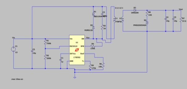
Fig5simulationoftheflybackconverter
The UVLO pin will have a voltage of 2.588V. If the voltage at pin point is less than 1.03V, the fly back regulatorIC will notfunction,hencethevoltageatpin point will be more than 1.03V. The simulated waveformisdepictedinFig6.

Fig6waveformoftheUVLOvoltage
Input voltage 12V applied to the Fly back converter with duty ratio of the 60%. The output voltage and output current of 15V and 400mA. Simulatedwaveformoftheoutputvoltageandcurrent asshownintheFig7.
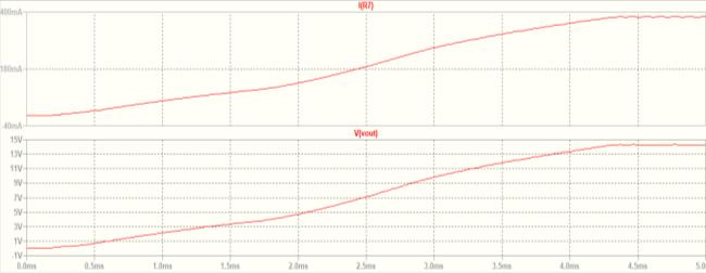
Fig7waveformoftheoutputvoltageandoutput current
During the discontinuous conduction mode (DCM),thevoltagerippleswillsettledowntobeginthe nextcycle.Thiswillemergeacrosstheswitchpinpoint during no load conditions, and the frequency under thispinwillbemorethan302kHz,asillustratedinthe simulatedwaveforminfig8.
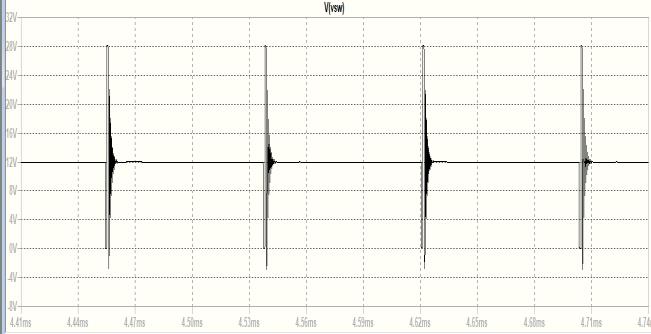
Fig8voltagewaveformatswitchduringDCM
During the continuous conduction mode (CCM), the load current was 400mA with a load resistance of 37.5 Ohm. During this mode, theleakage voltage will occur across the primary inductance, and thefrequencyoftheswitchpointwillbe320kHz,with thesimulatedwaveformgiveninFig9.
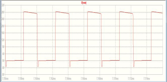
Fig9voltagewaveformacrosstheswitchduringCCM
Volume: 11 Issue: 08 | Aug 2024 www.irjet.net p-ISSN: 2395-0072 © 2024, IRJET | Impact Factor value: 8.315 |
B. SimulationcircuitusedtomeasuretheDCandphase voltageofthepowerboard
DC voltage is applied across the inverter circuit and converted into AC voltage. The AC voltage is measured in terms of phase voltage. DC voltage and phase voltage from the inverter's input and output were fed into voltage follower circuits, which clipped the higher voltage to 5V. The simulated circuits for sensing voltage deliver signals to the microcontroller, asshowninFig10.
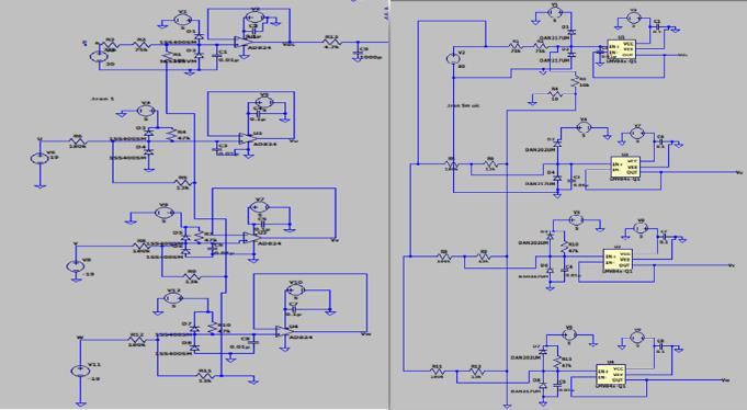
Fig10simulationcircuitsforthephaseandlinevoltage measurements
International Research Journal of Engineering and Technology (IRJET) e-ISSN: 2395-0056
Volume: 11 Issue: 08 | Aug 2024 www.irjet.net p-ISSN: 2395-0072
When DC voltage is provided to the inverter circuits. The voltage sensor measures the DC voltage across the inverter input and feeds it to the voltage divider circuits, where it is decreased to less than 5V. The voltage follower circuits will produce the same voltage across their non-inverting terminals and their outputs. Simulated circuits for the two conditions depictedinFig10.
When a DC voltage of 30 V is applied across the inverter circuits. The voltage in non-inverting and voltagedividercircuitswillbe1.875volts.Thevoltage at the output of the voltage follower circuits will displayas1.875V.Thewaveformshowninthefig11.
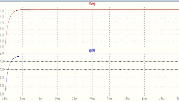
Fig11waveformforthemeasurementofDCvoltage lessthan30V.
WhentheDCvoltagedeliveredtotheinverter exceeds80V,thevoltageacrossthevoltagedividerand non-inverting terminal of the voltage follower circuit is greater than 5V. The voltage follower circuit operates at 5V, hence the voltage at the non-inverting terminal will be greater than 5V and then clipped to 5V.Sendsthevoltageleveltothemicrocontroller.The simulatedwaveformispresentedinfig12.
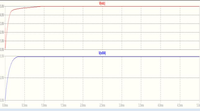
Fig12waveformforthemeasurementofDCvoltage morethan80V
When a DC voltage is applied to the inverter input, it is converted to an AC voltage and the phase voltage of the inverter's output is measured for each leg.Foranalysis,adifferentvoltageisdeliveredacross theinverterlegofthevoltagefollowercircuits,andthe
converted voltage signal is sent to the voltage comparator circuits to reset the microcontroller. The variouscriteriaarediscussedbelow.
When 75V is put across any one inverter leg, the voltage between the voltage divider circuits and non-invertingterminalsofthevoltagefollowercircuits is5.05V. The voltage followercircuitsareclipped into 5V,andthewaveformisillustratedinFigure13.
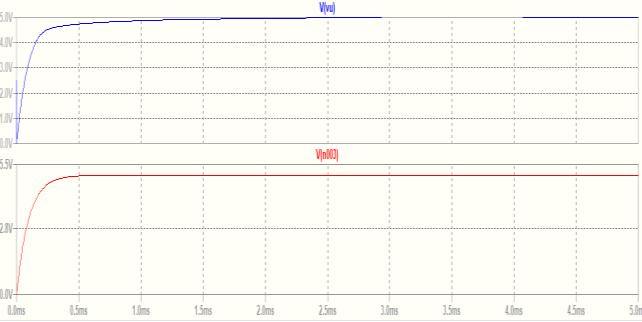
Fig13outputvoltageofthefollowercircuitwhenthe inputvoltageof75V
When 0V is supplied across any one inverter leg, the voltage between the voltage divider circuits and the non-inverting terminal of the voltage follower circuits is1.0253V.Thevoltagefollowercircuitssendavoltage of 1.0253V to the voltage comparator circuits and waveformillustratedinFig14.
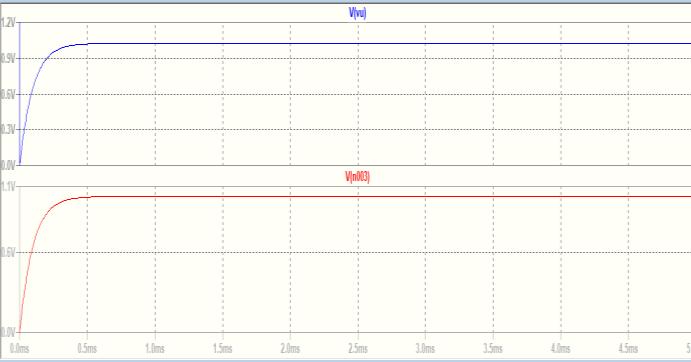
Fig14outputvoltageofthefollowercircuitwhenthe inputvoltageof0V
When -19V is applied to any one inverter leg, the voltage appearing across the voltage divider circuits and non-inverting terminals of the voltage follower circuits is 800mV. The voltage follower circuits transmit a voltage of 0V to the voltage comparator circuitsandwaveformdisplayedinFig15.
International Research Journal of Engineering and Technology (IRJET) e-ISSN: 2395-0056
Volume: 11 Issue: 08 | Aug 2024 www.irjet.net p-ISSN: 2395-0072
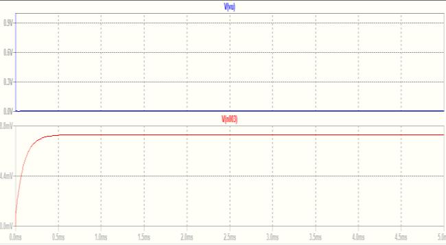
Fig14outputvoltageofthefollowercircuitwhenthe inputvoltageof-19V
C. Simulationforoverprotection(OV)unit
The voltage follower circuits' outputs are used to measure DC voltage. The voltage follower circuits' outputs convey the signal to the voltage comparator circuits. By comparing two distinct voltage levels and sending the signal to the microcontroller. When 5V is put across the voltage divider circuits, the voltage at the non-inverting terminal will be 3.75 V. The DC voltage of the voltage follower circuits will be comparedto3.75V.Ifthevoltageatthenon-inverting terminal (3.75V) is larger than the voltage at the inverting terminal, the voltage difference will be positive, allowing op-amp circuits to raise the voltage level to 5V. The simulated circuits and waveforms are presentedinFig15and16.
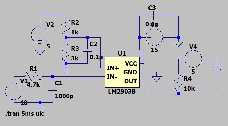
Fig15simulationcircuitforovervoltageprotection
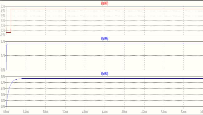
Fig16simulationwaveformdoesnotresettheMCU
When 5V is put across the voltage divider circuits, the voltage at the non-inverting terminal will be 3.75 V. The DC voltage of the voltage follower circuitswillbecomparedto3.75V.Ifthevoltageatthe non-invertingterminal(3.75V)islessthanthevoltage attheinvertingterminal,thevoltagedifferencewillbe negative, and the op-amp circuits will pull the voltage level down to 0V. The simulated circuits and waveformsareillustratedinFig17.
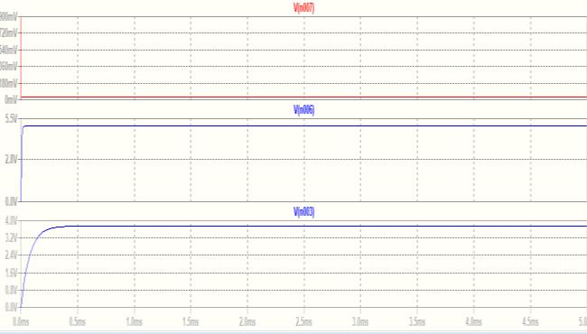
Fig17simulationwaveformresettheMCU D. Simulationforovercurrent(OC)protectionunit
The output current of the inverter circuits is measuredintermsofvoltageusingthecurrentsensor. TheoutputvoltageoftheU,V,andWlegsiscompared to the voltage levels of 4.5V and 500mV. If one of the voltage comparator circuits has a negative voltage difference, the microcontroller should be reset, and viceversa.ThesimulationcircuitsarepresentedinFig 18
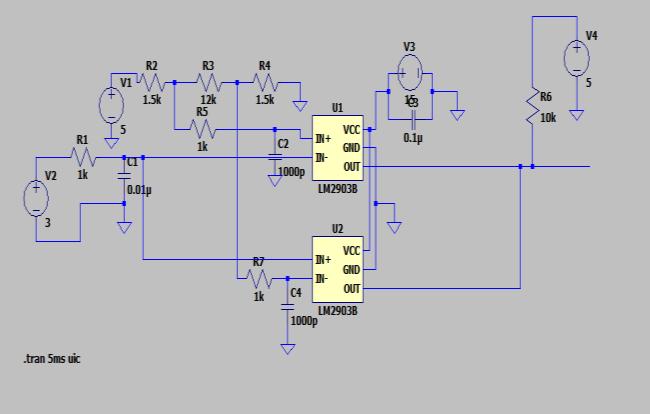
Fig18simulationcircuitfortheovercurrent
The voltage of each leg will be compared to the non-inverting terminal voltage of 4.5V and the inverting terminal voltage of 500mV. If the voltage difference is positive, the op-amp will pull up to 5V without resetting the MCU. The waveform depicted belowinFig19
International Research Journal of Engineering and Technology (IRJET) e-ISSN: 2395-0056
Volume: 11 Issue: 08 | Aug 2024 www.irjet.net
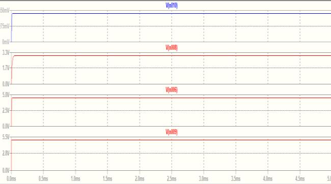
Fig19waveformfortheOCtestwhichpullupto5V
The voltage of each leg will be compared to the non-inverting terminal voltage of 4.5V and the inverting terminal voltage of 500mV. If the voltage differenceisnegative,theop-ampwillbepulleddown to 0V, resetting the MCU. The waveform illustrated belowFig20.
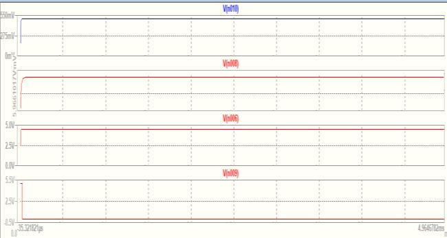
Fig20waveformfortheOCtestwhichwillberesetthe microcontroller
E. Simulationforthegatedrivercircuits
When a +15V input voltage is provided to the fly backconverter,itconvertstheoutputvoltageto+15V withadutyratioof50%andaloadcurrentof250mA. The fly back converter's input and output voltage are applied to the pulse width modulation (PWM) IC UCC27211.RectangularPWMpulsesareappliedtothe PWM IC at a frequency of 10kHz, with a dead time of 1500ns,risetimeof1ns,falltimeof1ns,anddutyratio of 50%. The simulated circuit diagram is depicted in Fig21.
p-ISSN: 2395-0072
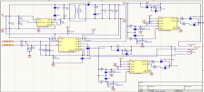
Fig21simulationcircuitofthegatedrivercircuit
WhenthePWMpulsesappliedtoUCC27211with an amplitude of the 5V. PWM IC which operating the voltagelevelof15VandpullupthePWMpulsesto15V asshownintheFig22.
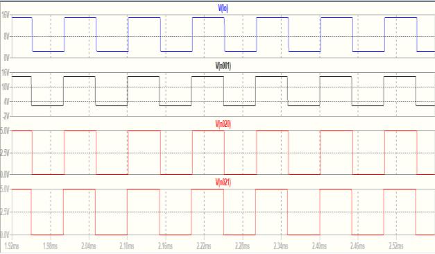
Fig22PWMpulsesgeneratedforUCC27211IC
The PWM pulses generated by the UCC27211ICaresenttotheUCC27524IC,whichpulls the PWM pulses up to 12V due to the difference ground,resultingin PWMpulsesof13V to15Vwitha 1500ns dead time. The simulated waveform is depictedinFig23.
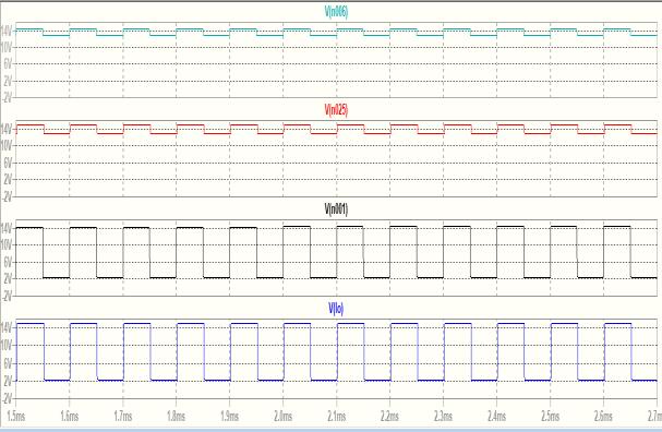
Fig23PWMpulsesgeneratedbytheUCC27524IC
F. Simualtionresult
PWM pulses are generated using gate driver circuitssuppliedtothepowerboard(invertercircuits)
International Research Journal of Engineering and Technology (IRJET) e-ISSN: 2395-0056
Volume: 11 Issue: 08 | Aug 2024 www.irjet.net p-ISSN: 2395-0072
to power the PMSM motor. The feedback from the PMSMmotor'ssilversectionwillbeusedtomodifythe positionofthePMSMmotorcontroller.TableIIIshows a tabulation of the motor running at various speeds, together with the torque and power consumed by the PMSMmotor.
TableIIIRequirementbasedonthesimulation
Thesimulationofthedesignanddevelopment of a resolver-based PMSM motor controller is shown. The research shows that the motor control unit used fullloadpowerataspeedof4000rpmandatorqueof 11.38Nmwasachieved.Resolversandencodersdetect the physical operational parameters of equipment in use. They typically measure the speed, position of the shaft,anddirectionofrotationoftherotor.Isimulated the overvoltage, overcurrent, and gate driver circuits. Generated the waveforms for each topology under varioussituations.
I deeply express my sincere gratitude to my guide Dr. S G Srivani, Associate professor, Dept. of EEE, RVCE, Principal and HOD, Dept. of EEE, RVCE and panel members for their valuable guidance throughout the project. I would also like to express my deepest appreciation to Takumi motion controls pvt.ltd, Bengaluru for providing me an opportunity to carry out the project in their organization and help me to gain hands on experience about the project.
[1] L. Cinti, C. Contò and N. Bianchi, "A Comparison between Hybrid Excited
Permanent Magnet and Wound Rotor Motor," 2022 International Symposium on Power Electronics, Electrical Drives, Automation and Motion(SPEEDAM), Sorrento, Italy, 2022, pp. 14-19, doi: 10.1109/SPEEDAM53979.2022.9842232.
[2] S. Wang, D. Peng and Z. Wu, "Embedded Position Detection for Permanent Magnet SynchronousMotorwithBuilt-InMagnets,"in IEEESensorsJournal, vol.19,no.21,pp.98189825, 1 Nov.1, 2023, doi: 10.1109/JSEN.2023.2928336.
[3] A. Deep, N. K. Pilli, A. K. Chauhan and S. K. Singh, "Design and development of rapid prototype controlled PMSM drive," 2022IEEE IAS Joint Industrial and Commercial Power Systems / Petroleum and Chemical Industry Conference (ICPSPCIC), Hyderabad, India, 2022, pp. 134-139, doi: 10.1109/CICPS.2022.7974065.
[4] K. A. Gore and R. T. Ugale, "Design and ComparativeAnalysisofPMSM,BLDC,SynRM, and PMAssi-SynRM Motors for Two-Wheeler Electric Vehicle Application," 2022 IEEE Conference on Interdisciplinary Approaches in Technology and Management for Social Innovation(IATMSI), Gwalior, India, 2022, pp. 1-6, doi: 10.1109/IATMSI56455.2022.10119363.
[5] J. You, P. Wang, Z. Liu and D. Jiang, "Vibration Analysis of Permanent Magnet Synchronous Motors Considering Rotor Position Error Caused by Resolver Static Eccentricity," 2023 IEEE 2nd International Power Electronics and Application Symposium (PEAS), Guangzhou, China, 2023, pp. 2348-2352, doi: 10.1109/PEAS58692.2023.10395452.
[6] S. Gupta, S. George and V. Awate, "PI ControllerDesignandApplicationforSVPWM Switching Technique Based FOC of PMSM," 2023 Second International Conference on TrendsinElectrical,Electronics,andComputer Engineering (TEECCON), Bangalore, India, 2023, pp. 172-177, doi: 10.1109/TEECCON59234.2023.10335784.
[7] R. Lajić and P. Matić, "Digital Position Control System with a BLDC Motor Using Field Oriented Control," 2023 22nd International Symposium INFOTEH-JAHORINA (INFOTEH), East Sarajevo, Bosnia and Herzegovina, 2023, pp. 1-6, doi: 10.1109/INFOTEH57020.2023.10094070.
International Research Journal of Engineering and Technology (IRJET) e-ISSN: 2395-0056
Volume: 11 Issue: 08 | Aug 2024 www.irjet.net p-ISSN: 2395-0072
[8] Aditi, S. Pandey, P. Kumar and M. Sreejeth, "AnalysisofAdvancedSpeedControlMethods for PLC-based Induction Motor Drive," 2021 International Conference on Recent Trends on Electronics, Information, Communication & Technology (RTEICT), Bangalore, India, 2021, pp. 610-614, doi: 10.1109/RTEICT52294.2021.9573894.
[9] A.Srivastava,R.Padgil,A.Gupta,A.Lohia and N. P. Nair, "Model-Based Sensored Field Oriented Control Implementation for PermanentMagnetSynchronousMotor," 2021 International Symposium of Asian Control Association on Intelligent Robotics and IndustrialAutomation(IRIA), Goa, India, 2021, pp. 337-344, doi: 10.1109/IRIA53009.2021.9588787.
[10] R. Gora, R. Biswas, R. K. Garg and U. Nangia, "Field Oriented Control of Permanent Magnet Synchronous Motor (PMSM) Driven Electric Vehicle and Its Performance Analysis," 2021 IEEE 4th International Conference on Computing, Power and Communication Technologies (GUCON), Kuala Lumpur, Malaysia, 2021, pp. 1-6, doi: 10.1109/GUCON50781.2021.9573814.
[11] S.K.SethuramanandM.G.Saravanan, "MicrocontrollerbasedPWMstrategiesforthe real-time control and condition monitoring of AC drives," 1993 Sixth International Conference on Electrical Machines and Drives (Conf. Publ. No. 376), Oxford, UK, 1993, pp. 400-405.
[12] H. Yu, "PWM regulation based on microcontroller control," 2022 International Conference on Electronics and Devices, Computational Science (ICEDCS), Marseille, France, 2022, pp. 34-36, doi: 10.1109/ICEDCS57360.2022.00014.
[13] A. M. Aljehaimi and A. A. Alrimali, "Speed Control of IPSMS Using Space Vector PWM," 2023 IEEE 3rd International Maghreb Meeting of the Conference on Sciences and TechniquesofAutomaticControlandComputer Engineering (MI-STA), Benghazi, Libya, 2023, pp. 111-116, doi: 10.1109/MISTA57575.2023.10169536.
[14] K.V.V.Satyanarayana,K.B.Shahand V.P.Chandran,"SpeedControlofMulticarrier PWM Based 11-Level Inverter Fed Induction Motor Drive," 2021 5th International
Conference on Electrical, Electronics, Communication, Computer Technologies and OptimizationTechniques(ICEECCOT), Mysuru, India, 2021, pp. 562-568, doi: 10.1109/ICEECCOT52851.2021.9708009.
[15] Qiang Li, Hai Huang and Binchuan Yin, "The study of PWM methods in permanent magnetbrushlessDCmotorspeed control system," 2008 International ConferenceonElectricalMachinesandSystems, Wuhan,2008,pp.3897-3900.
[16] S. Kotabagi, R. Nayak, S. Dalabanjan, V. P. N, P. L. Patil and S. Hemadri, "Maximum Power Point Tracking using Buck-Boost converter for EH-PMIC," 2023 36th International Conference on VLSI Design and 2023 22nd International Conference on EmbeddedSystems(VLSID), Hyderabad, India, 2023, pp. 1-6, doi: 10.1109/VLSID57277.2023.00052.
[17] S. Kotabagi, R. Nayak, S. Dalabanjan, V. P. N, P. L. Patil and S. Hemadri, "Maximum Power Point Tracking using Buck-Boost converter for EH-PMIC," 2023 36th International Conference on VLSI Design and 2023 22nd International Conference on EmbeddedSystems(VLSID), Hyderabad, India, 2023, pp. 1-6, doi: 10.1109/VLSID57277.2023.00052.
[18] A.Liyanage,M.Nagrial,A.Hellanyand J. Rizk, "Speed Control of Induction Motors UsingV/fControlMethod," 2022International Conference on Electrical and Computing TechnologiesandApplications(ICECTA),RasAl Khaimah, United Arab Emirates, 2022, pp. 424-429, doi: 10.1109/ICECTA57148.2022.9990374.
[19] S. Sakunthala, R. Kiranmayi and P. N. Mandadi,"Astudyonindustrialmotordrives: Comparison and applications of PMSM and BLDC motor drives," 2017 International Conference on Energy, Communication, Data Analytics and Soft Computing (ICECDS), Chennai, India, 2017, pp. 537-540, doi: 10.1109/ICECDS.2017.8390224.
[20] A. Mondal, J. Khan, S. Prins and K. S., "Control of Dual Motor Test Bench for Performance Testing of PMSM for Traction Application," 2023 IEEE Silchar Subsection Conference(SILCON), Silchar, India, 2023, pp.
International Research Journal of Engineering and Technology (IRJET) e-ISSN: 2395-0056
Volume: 11 Issue: 08 | Aug 2024 www.irjet.net p-ISSN: 2395-0072
© 2024, IRJET | Impact Factor value: 8.315 | ISO 9001:2008 Certified Journal | Page777 1-6, doi: 10.1109/SILCON59133.2023.10404719.
[21] A.M.LulheandT.N.Date,"Adesign& MATLAB simulation of motor drive used for electric vehicle," 2015 International Conference on Control, Instrumentation, Communication and Computational Technologies (ICCICCT), Kumaracoil, India, 2015, pp. 739-743, doi: 10.1109/ICCICCT.2015.7475378.
[22] S. S. Rauth and B. Samanta, "Comparative Analysis of IM/BLDC/PMSM Drives for Electric Vehicle Traction Applications Using ANN-Based FOC," 2020 IEEE 17th India Council International Conference(INDICON),NewDelhi,India,2020, pp. 1-8, doi: 10.1109/INDICON49873.2020.9342237.
[23] R.R.ChowdhuryandG.Koperundevi, "Motor Selection and Performance Assessment of SUV Electric Mobility Employing Indian Roads," 2022 IEEE 10th Power India International Conference (PIICON),New Delhi, India, 2022, pp. 1-6,doi: 10.1109/PIICON56320.2022.10045308.
[24] A. M. Lulhe and T. N. Date, "A technology review paper for drives used in electrical vehicle (EV) & hybrid electrical vehicles (HEV)," 2015 International Conference on Control, Instrumentation, Communication and Computational Technologies (ICCICCT), Kumaracoil, India, 2015, pp. 632-636, doi: 10.1109/ICCICCT.2015.7475355.
[25] D. S. Yadav and M. Manisha, "Electric PropulsionMotors:AComparativeReviewfor Electric and Hybrid Electric Vehicles," 2022 IEEE International Conference on Distributed Computing and Electrical Circuits and Electronics(ICDCECE),Ballari,India, 2022, pp. 1-6, doi: 10.1109/ICDCECE53908.2022.9793099.