
Volume: 11 Issue: 08 | Aug 2024 www.irjet.net p-ISSN:2395-0072

Volume: 11 Issue: 08 | Aug 2024 www.irjet.net p-ISSN:2395-0072
Preeti Gautam1 , Dr. Nand Kishore2
1M. Tech Scholar, Dept. of Electronics Engineering, Harcourt Butler Technical University, Uttar Pradesh India 2Assistant Professor, Dept. of Electronics Engineering, Harcourt Butler Technical University, Uttar Pradesh, India
Abstract - This article proposes a novel compact Eshaped wide-band planar filter-antenna design. Additionally, the impact of the type of dielectric material on the design's properties is examined and discussed. A monopole microstrip antenna cascaded with an E-shaped planar band-pass filter (BPF) forms the filter-antenna construction. This paper proposes a microstrip patch filtering antenna with a band-notched characteristic. The microstrip patch antenna has a bandwidth of 500 MHz TheCentrefrequencyis25.6GHz.Thefilter-antennadesign is simulated and optimized using HFSSv24 software. It is measured using a Rogers TMM 10i (tm) The substrate used has a height of 1.28 mm, a dielectric constant of 9.8, and a loss tangent of 0.0020. The structure is printed on a compact size of 29.28mmx16.5mmx1.28mm. A good agreement is obtained between the simulation and measurementperformance.
Key Words: Filtering antenna, High gain, 25.6 GHz, band-pass, Return loss,
Theworldisshiftingtowardautomationthesedays.Any nation's transportation network is its foundation. Transportation networks contribute to national prosperity. Thus,many antenna types thatcan regularly receive, send, or reply to signals are needed for an intelligenttransportationsystem.Therefore,amultiband antenna that simultaneously receives various resonant frequencies is needed. Therefore, a new filter is needed to get the necessary resonance frequency. An essential partofcreatingandexecutingIntelligentTransportation Systems(ITS)isWirelessLocalAreaNetworks(WLANs). The use of intelligent transportation systems (ITS) in transportation has several advantages, such as the development of new traffic models, the alleviation of congestion, and increased safety. ITS depends on a multitude of data sources, including voluntary data sharing by users and a variety of traffic and infrastructure sensors, to function well. Certain wellknown ITS apps, like as Waze and Google Traffic, are developedbybusinessesthatdon'tmakeitobvioushow they get this data from users [1]. ITS seeks to integrate cutting-edge communication technology into transportation networks to increase their sustainability,
safety, and efficiency.V2V, or vehicle-to-vehicle Vehicles may communicate directly with one another and share information about their position, speed, and direction thanks to WLAN. This aids in managing traffic and preventing collisions. Vehicle-to-infrastructure (V2I) Automobiles and roadside units with WLAN capabilities may converse. Drivers may receive real-time traffic updates, light timings, and other important information via this interaction. Real-time traffic data gathering and distribution are supported by WLAN networks. Traffic signal optimization, congestion control, and dynamic route assistance for vehicles may all be accomplished withtheuseofthisdata.CarRadarSystems:Preventing Collisions Road safety can be improved by vehicle radar systems that operate at 25.6 GHz, which can identify possible collisions and promptly alert drivers to them. Control of Traffic Signals for Infrastructure Communication To ease congestion and boost traffic efficiency, 25.6 GHz sensors may dynamically modify signal timings while keeping an eye on traffic flow. This work presents an effective microstrip filter operating in the 25.6 GHz frequency range. Reduce insertion loss to maintain the integrity of the signal. To enhance the properties of signal reflection, optimize return loss. Antennas and filters are essential parts of ultrawideband wireless communication equipment. Modern microstripantennashavetobesmalltofittiny,portable devices. Microstrip antennas are especially well-suited for UWB applications because of their lightweight design, low profile, affordability, and ease of manufacturing. Planar antennas come in a variety of forms and varieties, and a wealth of documentation demonstratestheirbasicimportancetoUWBtechnology. The filter antenna is designed to function at a center frequency of 25.6 GHz. To suppress undesired signals, a bandpassfilterwithnotchbandcharacteristicsisneeded to overcome this issue. However, to minimize insertion losses and system space, combining the band-pass filter and antenna into a single module is growing in popularity. Thus, certain filtering antennas It has been stated that filters have frequency responses such as to produce band-notch features, the Microstrip antenna is liberally combined with diffractive resonators, open stubs, parasitic strips, shorting wires, and multi-stub feeds[2].
International Research Journal of Engineering and Technology (IRJET)
Volume: 11 Issue: 08 | Aug 2024 www.irjet.net
Itisdemonstratedthatadipolemicrostripfilterantenna may yield a nearly circular gain pattern by using parasitic resonators. The parasitic components, which were used to produce two radiation nulls and two transmissionzerosoutsideofthebandinthebandwidth, The design is based on using stepped-impedance resonators. An F4B-2 substrate, kind of material was used in the design, having a thickness of 1.1 mm and a dielectric constant of 2.4. A 9 mm-high layer of air between the design includes ground layers and heated layers. The proposed filter antenna has a fractional BW of 4.2% and operates at 1.85 GHz. It generates strong signals in the targeted frequency band in addition to There are three shorting vias (connections to the ground), two strip lines, four lines, and a rectangular microstrip.Itisconstructedonan80x80mmsubstrate with a 4 mm thickness. The substrate material has a 2.6 is the dielectric constant and 0.003 is the loss tangent (δ). The antenna's broad bandwidth, which spans from 2.19GHzto2.68GHz,allowsittocoveralargefrequency range. and it performs best at 2.4 GHz. It keeps its efficiency above 90% while offering a powerful 9.5 dBi gain [3]. For upcoming wireless devices, a new filter antenna design with several layers is being introduced. The design includes three T-shaped microstrip antenna with transmission lines with open loop rings. Using efficiently reduces unwanted frequency range noise signals. [4]. Additionally, this balun filter-antenna configuration with a significant roll-off skirt factor is apparent. A fourth-order quasi-Yagi antenna is coupled to a multilayer balun microstrip filter in this configuration. Five-step impedance resonators are used by the balun filter to increase the passband rejection ratio. The filter antenna has a bandwidth of 22.9% and works at 2.5 GHz. At the passband's boundaries, it generates two transmission zeros. A 5.4 dBi gain and robustrejectionofundesiredsignalsareachievedbythe design. Benefits of the design include high signal suppressionanda broad bandwidthhowevermultilayer substrate technology is required. [5]. Recently, a novel small and strong microstrip filter antenna was created. This antenna performs well despite its modest size. It consists of Multilayer technology contributes to the design's compactness. The substrate used in the construction is a Rogers RT5880, this filter antenna is verythin(0.5mmthick)andhasamaterialthathelpsit workwellwithafrequencyof2.6GHz.Ithasagainof2.1 dB and a bandwidth of 2.8%, meaning it can pick up signals over a small range around that frequency. The mainbenefitofthisdesignisthatit'ssmallandcompact, but it has a complex structure because it uses several layers. [6]. In this work, a unique kind of antenna for usage in wireless communication systems is introduced. A Circular Polarize Ultra-Wide Band (UWB) filtenna is what it's known as. In addition to covering a large
e-ISSN:2395-0056
p-ISSN:2395-0072
frequencyrange,thisantennahastheabilitytofilteroffa particular band when required. The antenna has a feature that is included in its design and construction bandpass filter with an inverted T shape that aids in filteringparticularfrequencies.Italsofeaturesastepped patchintheshapeofasquare,whichisafeatureofUWB antenna.ThefrequencyrangeoftheUWBpatchantenna is 3 GHz to 14 GHz. Rogers 4350 material of a very low loss tangent of 0.0037 and a relative dielectric constant of 3.38, is used in the antenna's design. The antenna's base material has a thickness of 1.525.6 mm. The antennaissmallandstraightforward,anditisknownas anInvertedFAntenna(IFA).This"filtenna"iscapableof covering the whole Ultra-Wideband (UWB) frequency range, with the exception of one purposefully excluded band (the "notched band). The antenna produces a circular pattern by emitting signals in two distinct ways known as the E & H-plane polarizations. With a high peak gain of 6.8 dBi, it can efficiently send and receive signals in certain directions. The gain of the proposed IFA is considerably reduced in the notch band and outsideoftheUWBband[2].Lastyear,anewmicrostrip filtering antenna was introduced, which is made for 4G and 5G wireless networks. The filtering antenna, a crucial component of wireless devices' RF front ends, performs radiation and filtering duties. The filtering antenna features a hairpin bandpass filter and an ellipticalmicrostripantenna.Therightsizeofthehairpin filter helps achieve good impedance matching. The design is simple, compact, and coplanar, and it includes the bandpass filter. The antenna is built using FR4, a common material. Thickness of this material is 0.8 mm. The dielectric constant, which is 4.4 in this instance, is one of its characteristics. The loss tangent, which is 0.0025, is another significant characteristic. These characteristicsimpacttheantenna'sfunctionality.At 2.6 GHz,thefilter-antennaconfigurationisinoperation.The proposed filtering antenna's coplanar filter significantly reducesitsdesigncomplexityandcompactsit[7].
a)
In this manuscript, the design of a 25.6 GHz microstrip filter and filtering antenna has been proposed. The proposed design works in millimeter frequency range. The proposed filter is designed on substrate material Rogers TMM 10i (tm) having a dielectric constant of 9.8 withathicknessof1.28mm. Figure1(a)showsthetop layer of the filter and Figure 1 (b) shows the bottom layer of the filter. Figure 1(a) shows a 32.8 mm x 16.5 mm substrate material with a 1.1 mm thick microstrip lineatitscenter,withtwofeedpoints,Port-1andPort-2. ThemicrostriplineisconnectedwithdifferentE-shaped stubs on both side of line having parameters of L1, L2, L3,L4,L5,L6,andw3inmm.
Volume: 11 Issue: 08 | Aug 2024 www.irjet.net p-ISSN:2395-0072
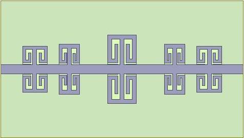

Fig-1: Shows(a)toplayer&(b)bottomlayerofthe filter.
Figure 1(b) shows a ground plane of length (L) in mm and width (W) in mm. The ground plane has slotted in consecutive manner. This structure makes defected ground structure. The slot is present just below the stubs.The parametersof theslotsareL1, L2,L3,L4, L5, L6andA2andA4.
Table-1: Parameter’svaluesofmicrostripfilter.
After the designing of band pass filter having centre frequency of 25.6, the designed is further modified to 25.6 GHz filtering antenna. For designing the filtering antenna,apatchisconnectedacrossanyoneoftheport. Thesizeofthepatchismodifiedbyandsetthevaluefor resonating at centre frequency of 25.6 GHz. The design andstructureoffilteringantennaareshowninfigure2.
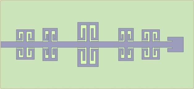
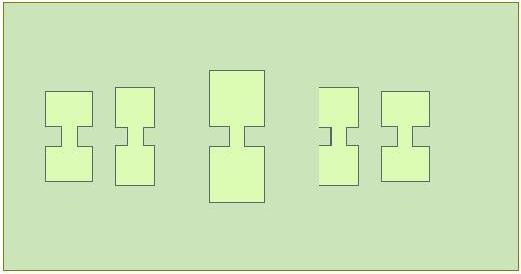
Fig-2: Shows(a)toplayer&(b)bottomlayerofthe microstripfilterantenna
Table-2: ParametervaluesoffilteringAntenna.
International Research Journal of Engineering and Technology (IRJET) e-ISSN:2395-0056
Volume: 11 Issue: 08 | Aug 2024 www.irjet.net p-ISSN:2395-0072
The proposed designed structure of filter and filtering antenna as show figure 1 & 2 are simulated in HFSSv25.6.theproposeddesignedhas simulatedforthe frequency range of 21 to 27 GHz at centre of 25.6GHz. theirparametersShowintable1&2.
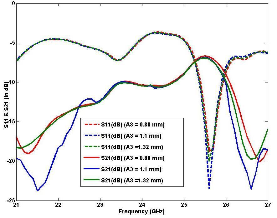
Fig.3. ParametricsimulatedS11(indB)&S21(indB)for parameterA3.
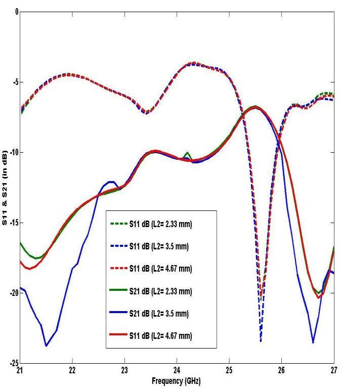
Fig-4: ParametricsimulatedS11(indB)&S21(indB)for parameterL2
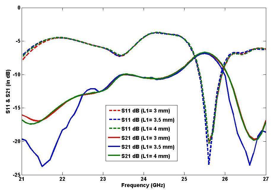
Fig-5: ParametricsimulatedS11(indB)&S21(indB)for parameterL1
The outcome of the parametric analysis in figure 3,4,5 . Thisisthereturnlossresult(indB)forthegroundplane slot specification. This result demonstrates that for A3=1.1mm, L1=3.5mm, L2=3.5mm. we obtain the appropriatesresonancefrequencyat25.6GHz.
Table-3: ParametricResult
Table 3 shows that parametric analysis result of different parameters i.e. A3, L1, L2. From this table it is clearly visible that for A3=1.1 mm, L1=3.5mm, L2=3.5mm is best fitted values for above design as shownasfigure1.
International Research Journal of Engineering and Technology (IRJET) e-ISSN:2395-0056
Volume: 11 Issue: 08 | Aug 2024 www.irjet.net p-ISSN:2395-0072
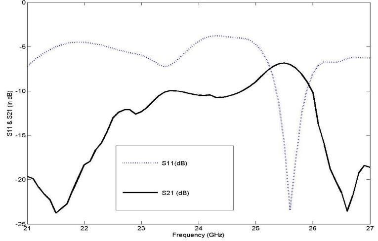
Fig-6: Shows simulatedS11(indB)&S21(indB).
Figure 6 shows the simulated S11(dB) & S21(in dB) for thefinalfilterdesigned.ThisresultshowsS11hascentre frequency of 25.6 GHz &-23.45dB. while the minimum S21 has the minimum S21 has values of -23.57dB. From thefigureitisclearlyshownthattheS21hascompletely pass the S11 band So this shows that the proposed designed is be haves like a band pass filters having centrefrequencyof25.6GHz.
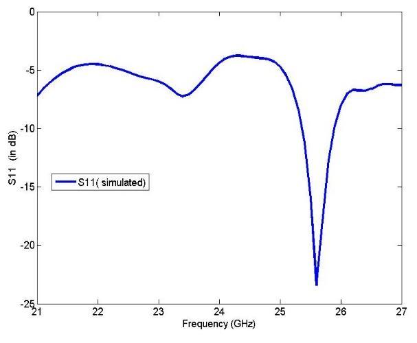
Fig-7: SimulatedS11(dB)ofFilteringAntenna.
After getting the propose filtering results the structure hasbeenmodifiedtofilteringantennaasshownfigure2. The figure 7 shows the S11 result of filtering antenna having resonant frequency of 25.6 GHz. The filtering antenna works in band range of 25.6 GHz to 25.9 GHz withapproximate500MHzbandwidth.
Simulated EPlane (in dB)
Fig-8: ShowssimulatedE-plane&H-planeofFiltering Antenna.
figure 8 shows that is simulated E-plane and H-plane resultatcentrefrequencyof25.6GHz.fromtheresultsit is clearly show that the filtering antenna is circularly polarized.
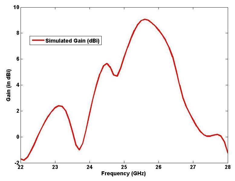
Fig-9: SimulatedGain(dBi)ofFilteringAntenna.
Figure 9 shows the simulated frequency (GHz) Uses us Gain(in dB) Plot. From the figure it shows that the peak gainof9.06dBi.
International Research Journal of Engineering and Technology (IRJET) e-ISSN:2395-0056
Volume: 11 Issue: 08 | Aug 2024 www.irjet.net p-ISSN:2395-0072
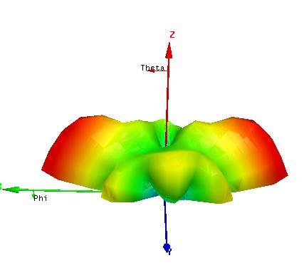
Fig-10: Simulated3Dpolarplotat25.6GHzoffiltering Antenna.
Figure10showsthe3-DpolarplotofGain(indB).
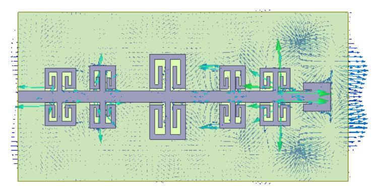
Fig-11: Simulatedvectorcurrentfielddistribution.
Fig.10 shows the surface vector current distribution overthepatchandgroundplane.
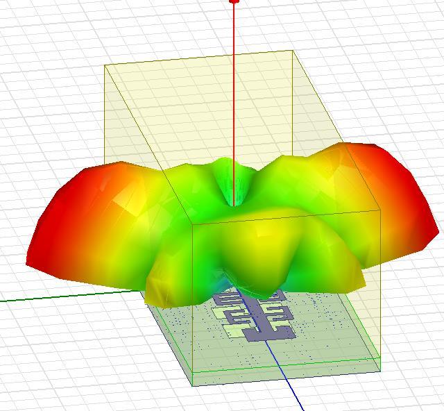
Fig.12 RadiationofFilteringAntenna
Table-4: Comparisonbetweentheproposeddesignand others.
This paper is present a compact 25.6 GHz WLAN microstrip filter play a crucial role in enhancing intelligent transportation systems (ITS). The compact filter design addresses the critical need for efficient, reliable, and high-speed communication in ITS applications, ensuring minimal interference and clear signal transmission. These designs have done by HFSSv25.6. The successful integration of this filter into ITS devices can lead to significant improvements in the performance and efficiency of transportation systems. By providing robust connectivity and high-speed data transfer, this technology contributes to the safety, reliability, and overall effectiveness of modern transportation networks. This advancement aligns with the broader goals of enhancing transportation safety, efficiency, and sustainability through cutting-edge communicationtechnologies.
[1] Gosman, Catalin, et al. “Controlling and Filtering Users Data in Intelligent Transportation System.” Future Generation Computer Systems, vol. 78, Jan. 2018, pp. 807https://doi.org/10.1016/j.future.2016.12.014. Accessed5Aug.2019.
[2] Ranjan, Prashant, and Amit Kumar. “Circularly Polarized Ultra–Wide Band Filtering Antenna with Controllable Band-Notch for Wireless CommunicationSystem.” AEU - International Journal of Electronics and Communications, vol. 135, June 2021, p. 153738, https://doi.org/10.1016/j.aeue.2021.153738. Accessed29Apr.2022
© 2024, IRJET | Impact Factor value: 8.226 | ISO 9001:2008 Certified Journal | Page113
International Research Journal of Engineering and Technology (IRJET) e-ISSN:2395-0056
Volume: 11 Issue: 08 | Aug 2024 www.irjet.net p-ISSN:2395-0072
[3] Alkhafaji,MohammedK.,etal.“StudyontheEffectof the Substrate Material Type and Thickness on the Performance of the Filtering Antenna Design.” TELKOMNIKA (Telecommunication Computing Electronics and Control), vol. 18, no. 1, 1 Feb. 2020, p. 72, https://doi.org/10.12928/telkomnika.v18i1.13189.
[4] “Dipole Filtering Antenna with Quasi‐Elliptic Peak Gain Response Using Parasitic Elements.” 781Microwave and Optical Technology Letters, vol. 61, no. 6, 28 Feb. 2019, pp. 1612–1616, https://doi.org/10.1002/mop.31848. Accessed 18 July2024
[5] Song, Lei, et al. “Wideband Balun Filtering Quasi‐Yagi Antenna with High Selectivity.” Microwave and Optical Technology Letters, vol. 61, no. 10, 20 June 2019, pp. 2336–2341, https://doi.org/10.1002/mop.31903. Accessed 26 July 2024.R. Nicole, “Title of paper with only first wordcapitalized,”J.NameStand.Abbrev.,inpress.
[6] Cui, Jingyu, et al. “Co‐Design of a Filtering Antenna BasedonMultilayerStructure.” International Journal of RF and Microwave Computer-Aided Engineering, vol. 30, no. 2, 16 Dec. 2019, https://doi.org/10.1002/mmce.22096. Accessed 26 July2024.
[7] Ramesh Boddu, et al. “Design of a Microstrip FilteringAntennafor4Gand5GWirelessNetworks.” Journal of Telecommunications and Information Technology, vol. 2, no. 2023, 29 June 2023, pp. 78–83, https://doi.org/10.26636/jtit.2023.171423. Accessed18July2024
[8] Abdel-Jabbar, Hana, et al. “Design and Optimization of Microstrip Filtering Antenna with Modified Shaped Slots and SIR Filter to Improve the Impedance Bandwidth.” TELKOMNIKA (Telecommunication Computing Electronics and Control), vol. 18, no. 1, 1 Feb. 2020, p. 545, https://doi.org/10.12928/telkomnika.v18i1.13532. Accessed3Oct.2022.
[9] A Compact Single-Layer Wideband Microstrip Antenna with Filtering Performance. Vol. 19, no. 5, 1 May 2020, pp. 801–805, https://doi.org/10.1109/lawp.2020.2980631
[10] Hua, C.; Liu, M.; Lu, Y. Planar integrated substrate integrated waveguide circularly polarized filtering antenna.Int.J.RFMicrow.Comput.AidedEng.2019, 29,e21517.