
International Research Journal of Engineering and Technology (IRJET) e-ISSN: 2395-0056
Volume: 11 Issue: 08 | Aug 2024 www.irjet.net p-ISSN: 2395-0072

International Research Journal of Engineering and Technology (IRJET) e-ISSN: 2395-0056
Volume: 11 Issue: 08 | Aug 2024 www.irjet.net p-ISSN: 2395-0072
1Sourabh M. Kadam, 2Dr.Chetan Patil
1Student Sanjay Ghodawat University Kolhapur, India.
2Profesor, Sanjay Ghodawat University Kolhapur, India.
Abstract - This study investigates the mechanical behavior and structural performance of conventional and BERP (Basalt Fiber Reinforced Polymer) composite beams through both experimental testing and Finite Element Method (FEM) analysis using ANSYS software. The primary objective is to evaluate and compare the performance characteristics of these beams under various loading conditions to determine their suitability for advanced structural applications. Experimental tests were conducted to gather empirical data on stress, strain, and deflection for both types of beams. Concurrently, FEM analysis in ANSYS was employed to simulate these conditions, enabling a comprehensive assessment of stress distribution, deformation patterns, and potential failure points. The results indicate a strong correlation between the experimental data and FEM simulations, affirming the reliability of the computational models. The BERP composite beams exhibited enhanced performance metrics, including higher strength, improved durability, and superior resistance to environmental factors, compared to their conventional counterparts. These findings suggest that BERP composite beams offer a promising alternative for applications demanding high-performance materials with extended service life and reduced maintenance requirements
Key Words: BasaltFiberReinforcedPolymersheets,wrapping,mechanicalproperties,FlexuralStrength,durability
1.INTRODUCTION
Recently,therehasbeenasignificantincreaseinthefocusondevelopinginfrastructureconstructedusingconcrete.Concrete structures,however,faceavarietyofissuesovertime,includingdegradation,increasedloaddemandsduetonewdesigncodes, overloading,poororinsufficientdesignofexistingstructures,lackofqualitycontrol,andchangesintheuseofthesestructures. Therapiddeteriorationofconcreteisaseriouschallengeforengineers,notonlyonthiscontinentbutglobally.Itisimperativeto addressstructuresdisplayingsignsofdegradationordamagepromptly.Iftheseissuesarenottreatedinatimelymanner,the structuresriskbecomingunsafeandunusable.Strengtheningorrepairingolderstructuresisessentialtomaintaintheirefficient serviceability and to fulfil the demands of newer constructions. Compared to the alternative of rebuilding, repairing or strengtheningexistingstructuresisadvantageousbotheconomicallyandenvironmentally.
Thereisoftenacorrelationbetweenthedeteriorationofinfrastructureandtheneedtomeetstricterdesigncriteria. This has led to a substantial increase in attention worldwide towards revitalizing infrastructure that results from civil engineering.Strengtheningandupgradingstructuresthatarestructurallydeficientordefectiveisbothatechnicallysoundand practicalmethod.Inadditiontodeterminingthestrengthofthematerial,itisnecessarytoinvestigatetheoriginofthedamage andpredictitsfutureperformance.Assessingtheremaininglifeofthesestructuresisofutmostimportance.Identifyingthecause ofdeteriorationandconductinganaccurateassessmentofthestructuralintegrityofthestructurescanmakerepairingthese structuresfinanciallyviableandextendtheirlifespan.
Membersthathavesufferedsignificantdamageshouldhavetheircurrentstatusevaluatedpromptly.Todeterminethefuture load-carryingcapacityandbehavioralcapabilitiesofthestructuralelements,variousparametersmustbeconsideredoncethe membersatriskofsignificantdamageareidentified.Toensureathoroughpost-repairevaluation,appropriatetestsutilizing non-destructivetestingmethodscanbeconducted.Underthesecircumstances,employingascientificandsystematicprocedure toevaluatethepropertiesofdamagedstructuresisoftheutmostimportance.Thisapproachensuresthattheevaluationis accurateandreliable,providingcrucialinformationtoguidetherepairandstrengtheningprocess.
In summary, the challenges posed by the deterioration of concrete structures require immediate attention and a systematicapproachtoevaluationandrepair.Byaddressingtheseissuespromptlyandeffectively,engineerscanextendthe lifespanofexistingstructures,ensuringtheirsafetyandfunctionalitywhilemeetingthedemandsofmoderndesigncodes.This approach not only enhances the sustainability ofinfrastructure butalso providessignificant economic and environmental benefits. .
International Research Journal of Engineering and Technology (IRJET) e-ISSN: 2395-0056
Volume: 11 Issue: 08 | Aug 2024 www.irjet.net p-ISSN: 2395-0072
Basaltfibersareformedbymeltingandmixingnaturalbasaltrockwithotherprimalmaterials.Thisproducesvarioustypes ofbasaltfiberswithdistinctproperties,suchashighstrength,resistancetochemicalsandheat,andlowdensity.Basaltfibersare versatilematerialswithauniquecombinationofproperties.Althoughbasaltfibersofferhighstrength,lowdensity,andan economicalprice.Manyoldconstructionsrequirerepairtopreventminorcracksfromleadingtostructuralfailureovertime. BasaltFiberSheetsofferasolutionforadvancedrepairtoextendthelifespanofbuildings.Variouswrappingtechniquescanbe selectedbasedoncrackpatternstoincreasethelifespanofbuildings
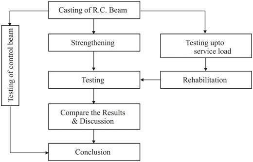
FollowingFigureNo.1showsthemethodologyadoptedfortheproposedwork.
A.TestSpecimens
The strength property of concrete are determined by casting specimens of cube size 150 mm×150 mm ×150 mm compression,beamofsize700mm×100mm×200mmforflexurestrengthandcured28days
B.Materials
ThedesignofaconcretemixforM20gradefollowsguidelinesprovidedbyIS456:2000andIS10262:2019.Here’sastepby-stepapproach:
Water-Cement Ratio:
ForM20gradeconcrete,awater-cement(w/c)ratioof0.45iscommonlyused.Thisratioisselectedbasedonexperienceand therequirementforachievingthedesiredworkabilityandstrength.
Water Content:
AccordingtoTable2ofIS10262:2019,theapproximatewatercontentforamaximumaggregatesizeof20mmis186kgfora slumprangeof25-50mm.Adjustmentstothisvaluemaybeneededbasedonspecificprojectrequirements.
Cement Content:
Theminimumcementcontentfordurability,asperIS456:2000,is320kg/m³.Verifythatthecalculatedcementcontent meetsthisminimumrequirement.
International Research Journal of Engineering and Technology (IRJET) e-ISSN: 2395-0056
Volume: 11 Issue: 08 | Aug 2024 www.irjet.net
Proportion of Coarse Aggregate:
BasedonIS10262:2019,foraw/cratioof0.50,thevolumeproportionofcoarseaggregate(bymass)isapproximately0.62. Thisproportionshouldbeadjustedbasedontheactualw/cratiousedinthemixdesign.
Calculation of Aggregates:
Computethemassofaggregatesbymultiplyingthevolumeofeachaggregatebyitsspecificgravity.Convertthesevolumesto masstodeterminethecorrectamountofeachaggregatetouse.
Mix Proportions:
ThefinalmixproportionsforM20gradeconcretearedeterminedasfollows:
Table1FinalmixofM30gradeconcretebyusingIS10262:2019(kg/m3)
ThecompressivestrengthofconcreteisakeypropertythatisassessedasperIndianStandards(IS).Thespecificcode governingthecompressivestrengthofconcreteisIS516:1959,Thestandardtestmethodfordeterminingthecompressive strengthofconcreteinvolvestestingacubespecimenofsize150mmx150mmx150mm.Thespecimenissubjectedtoa compressiveforceuntilfailure.Thecompressivestrengthiscalculatedastheloadappliedatthepointoffailuredividedbythe cross-sectionalareaofthespecimen.Concretecubesarecastandcuredforaspecificperiod,typically28days.Themachine shouldapplytheloaduniformlywithoutshockandincreasecontinuouslyataspecifiedrateuntilthespecimenfails.Theloadis appliedatarateof140kg/cm²perminute.
Table2Thecompressivestrengthofconcreteoffinalconcretemix.
Design of RC Beam as per IS 456 -2000
Tocalculatethecenterpointloadcarryingcapacityofasimplysupportedreinforcedconcrete(RC)beamusingthelimitstate methodasperIS456:2000.
Givendata:
1)Mainsteel-2#10atbottom
International Research Journal of Engineering and Technology (IRJET) e-ISSN: 2395-0056
Volume: 11 Issue: 08 | Aug 2024 www.irjet.net p-ISSN: 2395-0072
2)Topsteel-2#10attop
3)Stirrups-6T@125mm
Properties of BFRP
Table -3: ThepropertiesofBFRP
Weightofthesheetperm2(g/m2)
Properties Epoxy Resin
Table 4 : PropertiesofEpoxyResin
Property Epoxy Resin
Appearance Clearlowviscosityliquid
Viscosityat30°C 550-650cps
Type
Roomtemperaturecure
EpoxyEquivalent 180–200
SpecificGravityat30°C 1.1-1.2
StorageStability 1year
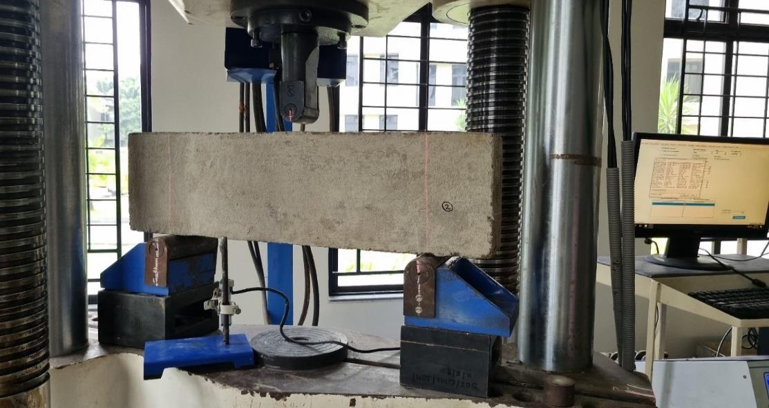
Testingareinforcedconcrete(RC)beamsectionunderthree-pointloadinginvolvesplacingthebeamonaUniversal TestingMachine(UTM)andapplyingaloadatasinglecentralpointwhilesupportingthebeamatbothends.Thistesthelps determinetheloadcarryingcapacityandbehaviorofthebeamunderload.Thetestingofareinforcedconcrete(RC)beamunder three-point loading is conducted using a Universal Testing Machine (UTM) with a capacity of 1200 kN. Here is a detailed procedureforconductingthistest:
a) Beam Specimen Preparation:
EnsuretheRCbeamispreparedaccordingtothespecifieddimensionsandcuringconditions.IfretrofittingwithBFRP, ensurethewrappingprocessiscompletedandtheepoxyhascuredproperly.
b) Setting Up the UTM:
PlacethebeamonthesupportsoftheUTM.Thesupportsshouldbeproperlyalignedandspacedtocreatetherequired spanlengthforthetest.Measureandsetthespanlengthbetweenthesupports,typicallytoastandardlengthsuchas500mm.
c) Test Procedure
Center the beam on the supports, ensuring it is aligned correctly with the loading apparatus. Attach any necessary measurementdevicessuchasstraingaugesordeflectionsensorsatthedesignatedlocationsonthebeam.
d) Applying the Load:
Graduallyapplytheloadataconstantratethroughtheloadinghead.Theloadshouldbeappliedsmoothlytoavoidany suddenshocks.Continuouslymonitortheloadanddeflectionreadings.Useadigitalindicatorordialgaugeplacedatthebottom centerofthebeamtomeasuredeflectionaccurately.
e) Observing the Beam:
CrackPatterns:Observeandrecordthedevelopmentofcracksonthebeamastheloadincreases.Notethelocations, orientations,andtypesofcracks(e.g.,flexuralorshearcracks).Continueapplyingtheloaduntilthebeamreachesitsmaximum loadcapacityandfails.Recordthemaximumload(P)thebeamcanwithstandbeforefailure.
International Research Journal of Engineering and Technology (IRJET) e-ISSN: 2395-0056
Volume: 11 Issue: 08 | Aug 2024 www.irjet.net p-ISSN: 2395-0072
f) Recording Data:
Recordthedeflectionreadingsatvariousloadincrements.Plottheload-deflectioncurvetoanalyzethebehaviorofthe beamunderload.
4.Result & Discussion
4.1 Load Carrying Capacity of RC Beams
Theload-carryingcapacityofreinforcedconcrete(RC)beamsisacriticalparameterinstructuralengineering,reflecting thebeam'sabilitytowithstandappliedloadswithoutfailing.Thiscapacityisdeterminedthroughvarioustestingandanalytical methods,withthethree-pointloadingtestinaUniversalTestingMachine(UTM).
Table5LoadcarryingcapacityforRCBeams
International Research Journal of Engineering and Technology (IRJET) e-ISSN: 2395-0056
Volume: 11 Issue: 08 | Aug 2024 www.irjet.net p-ISSN: 2395-0072
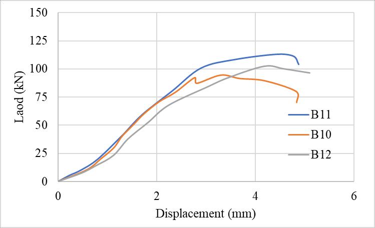
Figure3Theload-displacementcurvesforthreedifferentbeams
TheFigure3showstheload-displacementcurvesforthreedifferentbeams(B10,B11,andB12).Allthreebeamsshowsimilar initialstiffness,asindicatedbythesteepnessofthecurvesintheinitiallinearportionofthegraph.BeamB12exhibitsslightly lowerinitialstiffnesscomparedtoB10andB11,asitscurvestartstodeviatefromtheothersatlowerloads.Thefirstvisible deviationfromlinearity,whichcorrespondstotheformationofthefirstcrack,occursatdifferentloadlevelsforeachbeam. BeamB12reachesanoticeablecrackataround60-65kN,whileB10andB11showcrackingbehavioratslightlylowerloads. BeamB10hasthehighestultimateload,peakingcloseto113kNbeforefailure.BeamB11reachesaslightlylowerpeakload comparedtoB10,around95kN.BeamB12showsanultimateloadofabout102kN,whichislowerthanB10buthigherthan B11
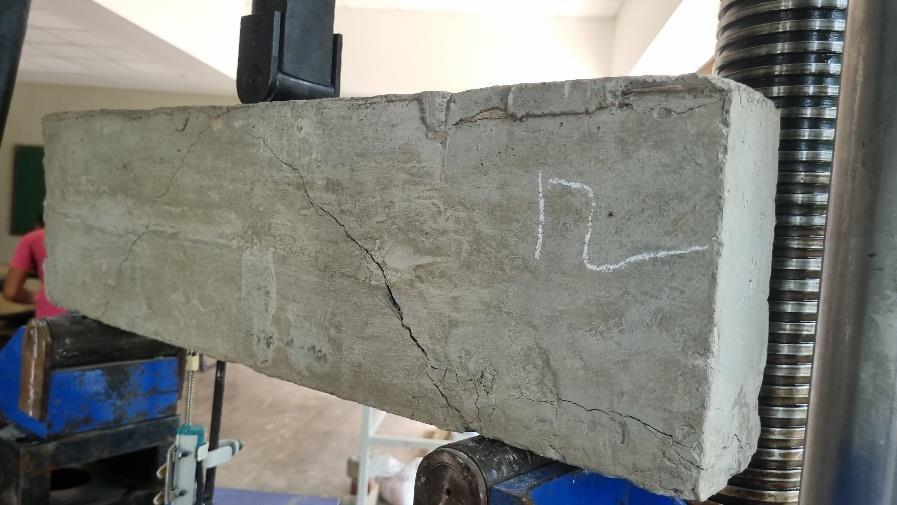
Figure Error! No text of specified style in document. ThecrackdevelopmentatultimateloadforRCbeams
International Research Journal of Engineering and Technology (IRJET) e-ISSN: 2395-0056
Volume: 11 Issue: 08 | Aug 2024 www.irjet.net p-ISSN: 2395-0072
Table6LoadcarryingcapacityforRCBeams@pre-cracking Beam
B1 71.06 2.365
B2 59.65 1.982
B3 50.37 2.340
B4 50.57 1.722
B5 54.11 2.179
B6 67.34 2.727
B7 51.07 2.226
B8 59.96 2.169
B9 59.29 1.989
The cracks are narrow andvertical start from the bottom surface of the beam(tensionface&bottom)andpropagateupwardtowardstheneutral axis.
The cracks are narrow andvertical start from the bottom surface of the beam(tensionface)andpropagateupwardtowardstheneutralaxis.
The cracks are narrow andvertical start from the bottom surface of the beam(tensionface)andpropagateupwardtowardstheneutralaxis.
Thescracksappearfineandstraight,typicallyformingperpendiculartothe beam'saxis.
Thescracksappearfineandstraight,typicallyformingperpendiculartothe beam'saxis.
The cracks are narrow andvertical start from the bottom surface of the beam(tensionface)andpropagateupwardtowardstheneutralaxis.
The cracks are narrow andvertical start from the bottom surface of the beam(tensionface&bottom)andpropagateupwardtowardstheneutral axis.
The cracks are narrow andvertical start from the bottom surface of the beam(tensionface&bottom)andpropagateupwardtowardstheneutral axis.
Thescracksappearfineandstraight,typicallyformingperpendiculartothe beam'saxis.
FromTable6,theloadatwhichthefirstcrackoccursvariesamongthebeams,rangingfrom50.37kNto71.06kN.Beam B1showsthehighestloadatthefirstcrack(71.06kN),indicatingahigherinitialstiffnessandpossiblybettermaterialproperties orreinforcementconfiguration.BeamB3hasthelowestloadatfirstcrack(50.37kN),suggestingthatitmayhavetheweakest performanceintermsofinitialload-carryingcapacityamongthetestedbeams.
Thedeflectionatthefirstcrackalsovaries,withvaluesrangingfrom1.722mmto2.727mm.BeamB4showsthesmallest deflectionatfirstcrack(1.722mm),indicatingastifferresponsetoloadinguptothepointofcracking.BeamB6exhibitsthe largestdeflectionatfirstcrack(2.727mm),whichsuggestsamoreductileresponsebutmayalsoindicatethepotentialforlarger deflectionsunderserviceloads.
BeamsB1,B2,B3,B6,B7,andB8exhibitnarrow,verticalcracksthatinitiateatthebottomsurface(tensionface)and propagateupwardtowardstheneutralaxis.Thiscrackpatternistypicalofflexuralfailureandindicatesthatthesebeamsare respondingtothetensilestressesintheexpectedmanner.BeamsB4,B5,andB9displayfineandstraightcracks,typically formingperpendiculartothebeam’saxis.Thesecrackssuggestamoreuniformstressdistributionandmayindicateadifferent crackingmechanismoradifferentstageofcrackdevelopment.
Thepresenceofnarrow,verticalcracksisconsistentwithexpectedflexuralbehaviorunderloading,wheretensilestresses causecrackingintheconcrete.Thefine,straightcracksobservedinsomebeamsmayindicateamoregradualcrackdevelopment oradifferentstressdistributionwithinthebeam.Thedeflectionsatfirstcrack,particularlyforbeamslikeB6withadeflectionof 2.727mm,indicatetheimportanceofconsideringdeflectionlimitsindesigntopreventexcessivecrackingandensurelong-term serviceabilityofthestructure.
International Research Journal of Engineering and Technology (IRJET) e-ISSN: 2395-0056
Volume: 11 Issue: 08 | Aug 2024 www.irjet.net p-ISSN: 2395-0072
Table7RetrofittingofRCbeamswithBFRP
Beam No Specimen Id. Description
B1 B1U WrappedwithasinglelayerofmultidirectionalBFRPfabric@twosidesandbottomface.
B2 B2S WrappedwithasinglelayerofmultidirectionalBFRPfabric@twosidesonly.
B3 B3S WrappedwithasinglelayerofmultidirectionalBFRPfabric@twosidesonly.
B4 B4B WrappedwithasinglelayerofmultidirectionalBFRPfabric@bottomfaceonly.
B5 B5B WrappedwithasinglelayerofmultidirectionalBFRPfabric@bottomfaceonly.
B6 B6S WrappedwithasinglelayerofmultidirectionalBFRPfabric@twosidesonly.
B7 B7U WrappedwithasinglelayerofmultidirectionalBFRPfabric@twosidesandbottomface.
B8 B8U WrappedwithasinglelayerofmultidirectionalBFRPfabric@twosidesandbottomface.
B9 B9B WrappedwithasinglelayerofmultidirectionalBFRPfabric@bottomfaceonly.
4.3 The RC Beams with BFRP Fabric @ Two Sides and Bottom Face (BU).
Areinforcedconcrete(RC)beamwithBasaltFiberReinforcedPolymer(BFRP)fabricontwosidesandthebottomface.
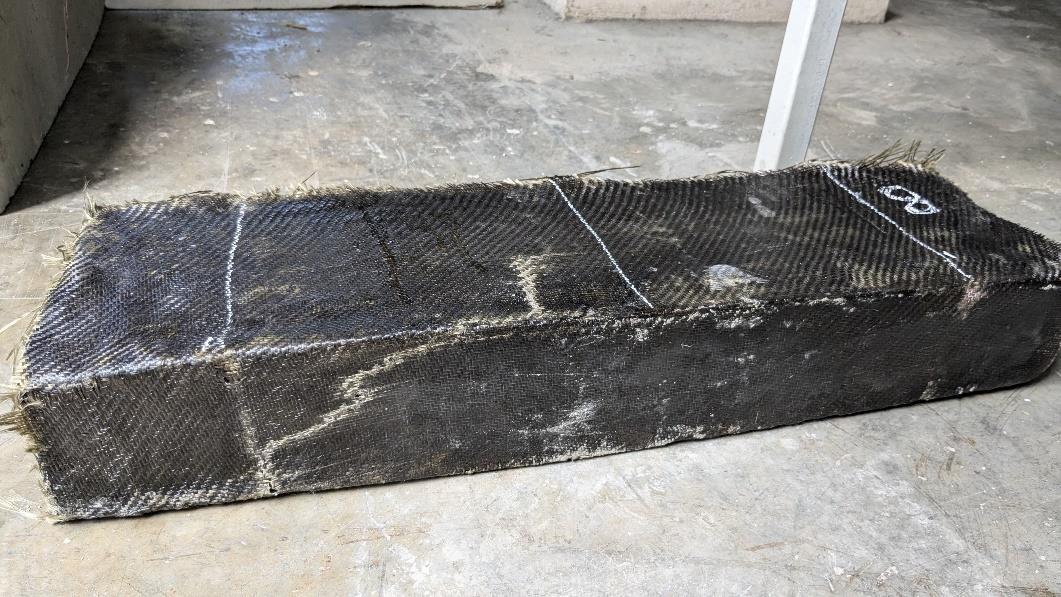
The experimental results for the RC beams retrofitted with Basalt Fiber Reinforced Polymer (BFRP) fabric reveal notable improvementsinperformance.Thebeamsweretestedtofailureundercontrolledconditions,andthedatacollectedincludesthe loadatfailureanddeflectionatfailureforeachbeam.TheresultsforthebeamsretrofittedwithBFRPfabric,denotedasB1U, B7U,andB8U,aresummarizedinTable6.TheaverageloadatfailurefortheBFRP-retrofittedbeamsis123.06kN,whichis significantlyhighercomparedtothecontrolbeam,whichhadanaveragefailureloadof102.72kN.Thecomparisonshowsthat
International Research Journal of Engineering and Technology (IRJET) e-ISSN: 2395-0056
Volume: 11 Issue: 08 | Aug 2024 www.irjet.net p-ISSN: 2395-0072
theretrofittedbeamsexhibitasubstantialincreaseinload-carryingcapacity.Theaverageincreaseinload-carryingcapacityfor theBFRP-retrofittedbeamsisapproximately19.8%.ThisenhancementindicatesthattheBFRPfabriciseffectiveinincreasing thestructuralstrengthofRCbeams.Whiletheload-carryingcapacityhasincreased,thereisanotablevariationindeflection amongtheBFRP-retrofittedbeams.Thedeflectionsatfailurefortheretrofittedbeamsrangedfrom4.609mmto7.015mm.This variabilitycouldbeattributedtodifferencesintheapplicationoftheBFRPfabric,surfacepreparation,orotherexperimental factors.
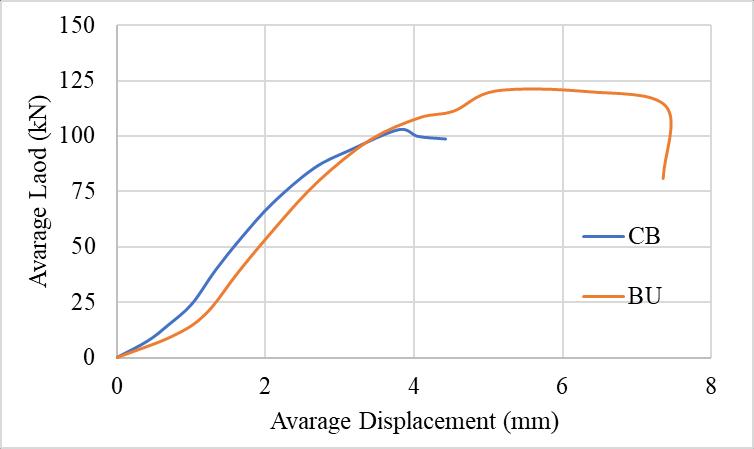
Figure6Theloaddeflectioncurveforcontrolbeam(CB)&RCBeamswithBFRPfabric@twosidesandbottomface(BU)
Figure6presentstheload-deflectionbehaviorofthecontrolbeam(CB)andanRCbeamretrofittedwithBFRPfabricon twosidesandthebottomface(BU).Thecurvesillustratehowbothbeamsrespondtoincreasingloads,providinginsightinto theirstiffness,strength,andfailuremodes.Intheinitialloadingphase,bothbeamsexhibitalinearrelationshipbetweenloadand displacement,indicatingelasticbehavior.Theslopesofthecurvesinthisregionsuggestthatthestiffnessoftheretrofittedbeam (BU)isslightlyhigherthanthatofthecontrolbeam(CB).ThissuggeststhattheBFRPfabricenhancesthebeam'sinitialrigidity.
4.4 The RC Beams with BFRP Fabric @ Two Sides Face Only (BS).
Areinforcedconcrete(RC)beamwithBasaltFiberReinforcedPolymer(BFRP)fabricontwosidesface
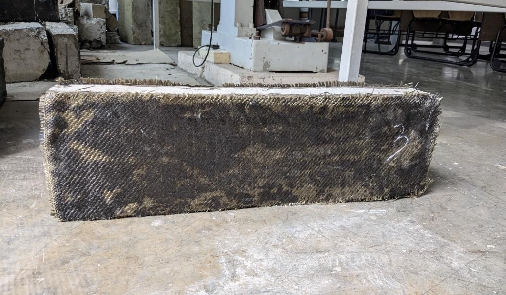
7TheRCBeamwithBFRPfabric@twosidesfaceonly
International Research Journal of Engineering and Technology (IRJET) e-ISSN: 2395-0056
Volume: 11 Issue: 08 | Aug 2024 www.irjet.net p-ISSN: 2395-0072
10
TheexperimentalresultshighlighttheeffectofBFRPretrofittingontheload-carryingcapacityofRCbeams.Theaverage loadatfailureforthebeamsretrofittedwithBFRPontwosides(BS)wasfoundtobe105.58kN.Whencomparedtothecontrol beam(CB),whichhadanaveragefailureloadof102.72kN,theretrofittedbeamsshoweda modestimprovementinloadcarryingcapacity,withapercentageincreaseofapproximately2.79%.ThisincreasesuggeststhatBFRPretrofittingontwosides enhancesthestructuralcapacityofthebeam,althoughtheimprovementisrelativelyminorcomparedtootherconfigurations, suchasfullU-wrapping.ThemodestgainmaybeduetothelimitedsurfaceareacoveredbytheBFRPfabric,whichonlypartially supportsthebeamunderflexuralstress.
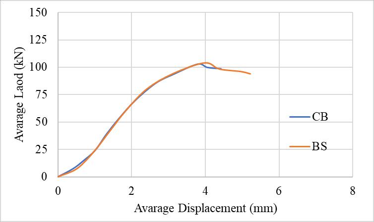
Figure8Theloaddeflectioncurveforcontrolbeam(CB)&RCBeamswithBFRPfabric@twosidesonly(BS)
Figure8comparestheload-deflectionbehaviorofthecontrolbeam(CB)withthatofanRCbeamretrofittedwithBFRP fabricontwosidesonly(BS).Bothbeamsexhibitalinearload-deflectionrelationshipintheinitialphase,indicatingelastic behavior.ThesimilarityintheslopesofthetwocurvesduringthisphasesuggeststhattheBFRPfabriconthesidesdoesnot significantlyaltertheinitialstiffnessofthebeam.Astheloadincreases,bothbeamsbegintoexhibitnonlinearbehavior,typically associatedwiththeonsetofcrackingandotherinelasticdeformations.Theretrofittedbeam(BS)showsaslightlydelayed transitionintothenonlinearrangecomparedtothecontrolbeam(CB),indicatingthattheside-appliedBFRPfabricprovides someadditionalresistancetoinitialcracking.
International Research Journal of Engineering and Technology (IRJET) e-ISSN: 2395-0056
Volume: 11 Issue: 08 | Aug 2024 www.irjet.net p-ISSN: 2395-0072
4.5 The RC Beams with BFRP Fabric @ Bottom Face Only (BB).
Areinforcedconcrete(RC)beamwithBasaltFiberReinforcedPolymer(BFRP)fabricontwosidesface.
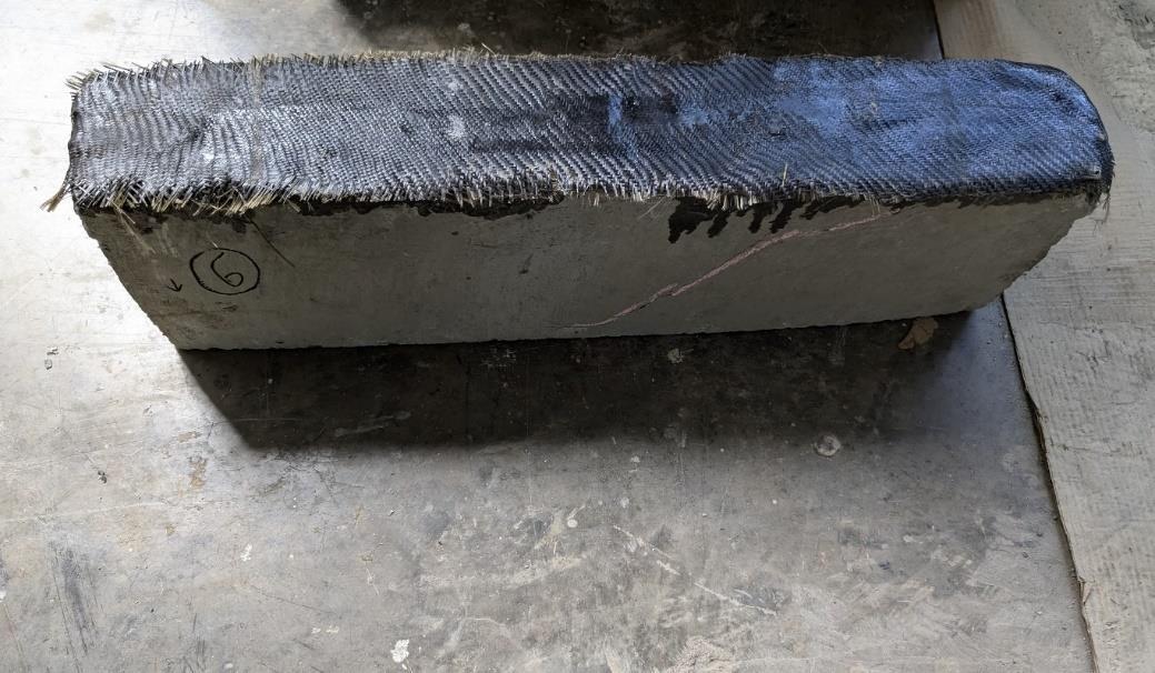
Figure9TheRCBeamwithBFRPfabric@twosidesfaceonly
Table11LoadcarryingcapacityforRCBeamswithBFRPfabric@bottomsidesonly(BB)
TheexperimentalanalysisoftheRCbeamsretrofittedwithBFRPfabriconthebottomsideonly(BB)showsanotable improvementintheirload-carryingcapacity.Theaverageloadatfailurefortheseretrofittedbeamswasfoundtobe120.90kN. This is a significant enhancement compared to the control beam, which had an average load at failure of 102.72 kN. The application of BFRP on the bottom face alone led to a 17.7% increase in load-carrying capacity. This result highlights the effectiveness of BFRP retrofitting in strengthening RC beams, even when applied only to the bottom side. The increase in capacitycanbeattributedtotheadditionaltensilereinforcementprovidedbytheBFRPfabric,whicheffectivelyresiststhe tensileforcesinducedbybending.
International Research Journal of Engineering and Technology (IRJET) e-ISSN: 2395-0056
Volume: 11 Issue: 08 | Aug 2024 www.irjet.net p-ISSN: 2395-0072
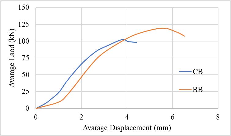
Figure10Theloaddeflectioncurveforcontrolbeam(CB)&RCBeamswithBFRPfabric@bottomface(BB)
Figure10illustratestheload-deflectionresponseofthecontrolbeam(CB)comparedtoanRCbeamretrofittedwithBFRP fabriconthebottomfaceonly(BB).Bothbeamsdemonstratealinearrelationshipbetweenloadanddisplacementduringthe initialloadingphase,reflectingelasticbehavior.Theretrofittedbeam(BB)appearstohaveaslightlylowerinitialstiffness comparedtothecontrolbeam,asindicatedbythemoregradualslopeofthecurveintheelasticregion.Astheloadincreases, bothbeamsexhibitnonlinearbehavior,whichcorrespondstotheinitiationofcrackingandotherinelasticdeformations.The retrofittedbeam(BB)startsshowingsignsofnonlinearityataslightlyhigherloadthanthecontrolbeam,indicatingthatthe BFRPfabriconthebottomfaceeffectivelyenhancesthebeam'sresistancetocrackingandinitialdamage.
5 Conclusion
Enhanced Load-Carrying Capacity:
1. Theretrofittedbeamsexhibitedamarkedimprovementinload-carryingcapacitycomparedtothecontrolbeam(CB). TheBUconfigurationdemonstratedthemostsignificantenhancement,achievinga17.7%increaseinloadcapacityover thecontrolbeam,withanaveragefailureloadof120.30kNcomparedtothecontrolbeam’s102.72kN.
2. TheBBconfigurationalsoshowedasubstantialincrease,withanaveragefailureloadof105.58kN,resultingina2.79% improvementoverthecontrolbeam.TheBSconfiguration,whilelessimpactful,stillprovidedbenefitsinloadcapacity.
1. Thedeflectioncapacityatfailurewassignificantlyimprovedintheretrofittedbeams.Forinstance,theBBconfiguration allowedthebeamtoreachadeflectionof6.449mmatfailure,indicatingimprovedductilitycomparedtothecontrol beam.
2. TheBUconfigurationalsoshowedenhancedductility,withdeflectionsupto7.015mm,allowingthebeamtosustain higherloadswithincreaseddeformationbeforefailure.
Theload-deflectioncurvesindicatedthattheretrofittedbeams,especiallythoseintheBUandBBconfigurations, experiencedamorecontrolledandductilefailurecomparedtothecontrolbeam.Thegradualdeclineinloadafter reachingpeakcapacitysuggeststhatBFRPretrofittingenhancesthebeam'sabilitytoabsorbenergyandresistcollapse, whichiscriticalinstructuralapplications.
International Research Journal of Engineering and Technology (IRJET) e-ISSN: 2395-0056
Volume: 11 Issue: 08 | Aug 2024 www.irjet.net p-ISSN: 2395-0072
Strategic Retrofitting Effectiveness:
The study confirms that the strategic placement of BFRP fabric, particularly on the bottom face of RC beams, significantly enhances structural performance. The BB and BU configurations provided the best combination of increased load capacity and improved ductility, making these configurations particularly effective for retrofitting purposes.
Future Research Directions:
Furtherstudiesshouldinvestigatethelong-termperformanceofBFRP-retrofittedbeamsunderenvironmentaland cyclicloadingconditions.Additionally,exploringdifferentfiberorientationsandtheuseofhybridmaterialscould furtheroptimizeretrofittingstrategies.
ACICommittee440(2015).GuidefortheDesignandConstructionofStructuralConcreteReinforcedwithFiber-Reinforced Polymer(FRP)Bars(ACI440.1R-15).AmericanConcreteInstitute,FarmingtonHills,MI.
ANSYS Inc. (2023). ANSYS Mechanical APDL Documentation. [Online] Available: https://www.ansys.com/products/structures/ansys-mechanical
Bischoff,P.H.,&Perry,S.H.(1991)."Compressivebehaviourofconcreteathighstrainrates."MaterialsandStructures,24, 425-450.
Chajes,M.J.,Finch,W.W.,Januszka,T.F.,&Thomson,T.A.(1996)."BondandForceTransferofCompositeMaterialPlates BondedtoConcrete."ACIStructuralJournal,93(2),208-217.
Chen,J.F.,&Teng,J.G.(2003)."ShearcapacityofFRP-strengthenedRCbeams:FRPdebonding."ConstructionandBuilding Materials,17(1),27-41.
GangaRao,H.V.S.,&Vijay,P.V.(1998)."BendingBehaviorofConcreteBeamsWrappedwithCarbonFabric."Journalof StructuralEngineering,124(1),3-10.
IS456:2000(2000).IndianStandardPlainandReinforcedConcrete-CodeofPractice.BureauofIndianStandards,NewDelhi.
Malek,A.M.,&Saadatmanesh,H.(1998)."AnalyticalStudyofReinforcedConcreteBeamsStrengthenedwithFRPPlates." JournalofStructuralEngineering,124(9),1039-1052.
Nanni,A.,&Bradford,N.M.(1995)."FRPjacketedconcreteunderuniaxialcompression."ConstructionandBuildingMaterials, 9(2),115-124.
Park,R.,&Paulay,T.(1975).ReinforcedConcreteStructures.JohnWiley&Sons,NewYork.
Teng,J.G.,Chen,J.F.,Smith,S.T.,&Lam,L.(2002).FRP-StrengthenedRCStructures.JohnWiley&Sons,WestSussex,England.
Triantafillou,T.C.,&Plevris,N.(1992)."StrengtheningofRCbeamswithepoxy-bondedfibre-compositematerials."Materials andStructures,25(4),201-211.
Xiong,G.,Wu,Z.,&Liu,H.(2007)."Experimentalstudyontheflexuralbehaviorofreinforcedconcretebeamsstrengthened withnear-surfacemountedCFRPstrips."JournalofCompositesforConstruction,11(4),383-389.
Zhang,Z.&Hsu,C.T.T.(2005)."ShearStrengtheningofReinforcedConcreteBeamsUsingCarbon-Fiber-ReinforcedPolymer Laminates."JournalofCompositesforConstruction,9(2),158-169.
Zhou,Y.,&Teng,J.G.(2006)."ShearbehaviorofFRP-strengthenedRCbeams:Assessmentofexistingmodels."Journalof CompositesforConstruction,10(4),291-303.