
International Research Journal of Engineering and Technology (IRJET) e-ISSN:2395-0056
Volume: 11 Issue: 08 | Aug 2024 www.irjet.net p-ISSN:2395-0072

International Research Journal of Engineering and Technology (IRJET) e-ISSN:2395-0056
Volume: 11 Issue: 08 | Aug 2024 www.irjet.net p-ISSN:2395-0072
Sumer Singh#1
#College Of Technology and Engineering, Udaipur
Abstract -With the changing attitude of society towards the environment, the use of laser welded blanks could be very beneficial to the automotive industries. This includes reducing scrap from manufacturing and making their productmoreenergyefficient. Alongwiththereductionof scrap, the automotive industry is subjected to more and more stringent government regulation for fuel efficiency. Thereiscurrentlyalargeinterestindevelopinglightweight alloysthatcanbeusedinanautomobiletoreplaceheavier steel parts, resulting in weight reductions of the vehicle without sacrificing strength. Metallic material such as aluminium and magnesium, high-strength steels, carboncarbon composites as well as a number of novel metallic composites is all under investigation in terms of viability andpracticalityforuseinhighproductioninautomobile.
Auniquecombinationofpropertiesputsaluminiumandits alloys amongst our most versatile engineering and construction materials. All alloys are light in weight, yet some have strengths greater than that of structural steel. For automotive applications aluminium alloy sheets have the advantages of corrosion resistance, high strength to weightratio,andrecyclability.
Laser, electron beam, tungsten inert gas, metal inert gas and friction stir welding processes have been used for creating tailor welded blanks. However, due to the small heat effected zone (HAZ) and fusion zone, the laser and electron beam welding process produce less impact on materialpropertiesthanothers.Laserweldinghasbeenthe most frequently used process for producing TWBs due to the lower cost and greater flexibility compared to those of electron beam welding. However, there are several difficulties to develop TWB particularly for aluminum and magnesium alloys because of their high reflectivity, low molten viscosity and inherent oxide layer, conventional laser welding leads to hot cracking in the fusion zone and the poor coupling during welding process. Therefore, as a newly emerging welding technology for TWB, friction stir welding (FSW) was developed primarily for aluminum alloys. Friction stir welding was invented by Wayne ThomasatTWI(TheWeldingInstitute),andthefirstpatent applications were filed in the UK in December 1991. Initially, the process was regarded as a “laboratory” curiosity, but it soon became clear that FSW offers numerousbenefitsinthefabricationofAluminumproducts.
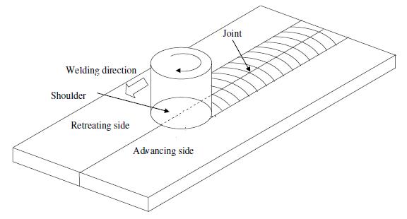
Friction stir welding (FSW) is a solid–state, hot–shear joiningprocessinwhicharotatingtoolwithashoulderand a pin, moves along the butting surfaces of two rigidly clamped plates placed on a backing plate as shown in Fig. 1.1Theshouldermakescontactwiththetopsurfaceof the work–piece. Heat generated by friction at the shoulder surface, softens the material being welded. Severe plastic deformationandflowofthisplasticizedmetaloccursasthe tool is translated along the welding direction. Material is transported from the front of the tool to the trailing edge whereitisforgedintoajoint.AlthoughFig.1.1showsabutt joint forillustration,other typesofjointssuchaslapjoints andfilletjointscanalsobefabricatedbyFSW.Thewelding technologyfortailorweldedblankiswellestablished.What is not understood is the forming characteristics of the TWBs. The problem is the prediction of how the process parameters will influence the weld quality and how the location of welds will influence the formability and their mechanical properties. In this project I will perform the friction stir welding process for producing tailor welded blanks and study the influence of process parameters on weld quality and perform formability test along with
Volume: 11 Issue: 08 | Aug 2024 www.irjet.net
uniaxial tensile test and microhardness test. Further detailed description mentioned in the literature review whichisinthechapter-
In the present work the TWBs made by FSW process and studytheeffectofprocessparameteronweldquality.
The following were used for the Friction Stir Welding ProcessofAluminiumalloysheets.
1. VerticalMillingmachine
2. Fixture
3. BackingPlate
4. Tool
5. Specimen
1. Fixture: A fixture is a work-holding or support device used in various manufacturing processes. The main purpose of a fixture is to locate and in some cases hold a workpiece during a machining operation
All weld samples are shown above in fig 3.5. Equation 2.1 showsthatathigherrotationalspeedtheheatgenerationis high which is clearly shown in above figure 3.5 c, d. High heat generation causes more amount of material flash out during welding and less heat generation causes improper bonding between strips, which is undesirable. Therefore optimumrangeofspeed,whichwasusedinthisexperiment, is in between 450 rpm to 710 rpm. Common defects in friction stir welds include porosity and surface defects [1]. Common defects in friction stir welds include porosity and surface defects [1]. At a constant rotational speed, an increase in the travel speed leads to wormhole initiation near the bottom of the weld. Furthermore, the size of the wormholes increases with the travel speed because of inadequate material flow towards the bottom of the weld. There are indications that the travel speed to rotational speedratioisanimportantvariableinthe formationofthe wormholedefect.Forthesamematerialandtoolgeometry, a high ratio tends to favor the formation of wormhole defects. That’s why it was restricted f Most of the heat generation occurs at the interface between the tool shoulder and the work–piece. Significant heterogeneity in heat generation at that interface can lead to defect formation in the form of excess flash due to surface overheating.
The quality of FSW welds is greatly dependent on the selection of process parameters such as welding speed (mm/min), rotation speed (rpm) and tool diameter. Since the heat generation [eq. 2.1] in weld nugget zone plays an importantroleindeterminingthemechanicalpropertiesof
the weld. Therefore, it is very important to select the welding process parameters for obtaining optimal heat in the weld nugget zone. In the welding was carried out by using the selected variations of parameters as shown in Table1 which is obtained by Taguchi’s orthogonal array method. The Taguchi method involves reducing the variationinaprocessthroughrobustdesignofexperiments. The experimental design proposed by Taguchi involves using orthogonal arrays to organize the parameters affectingtheprocessandthelevelsatwhichtheyshouldbe varies. Instead of having to test all possible combinations like the factorial design, the Taguchi method tests pairs of combinations. This allows for the collection of the necessary data to determine which factors most affect product quality with a minimum amount of experimentation,thussavingtimeandresources. Primarily visual inspection evaluate the good quality of welds were obtainsbyFSW.Fourweldsweredevelopingoneachsetof parameters.
International Research Journal of Engineering and Technology (IRJET) e-ISSN:2395-0056
Volume: 11 Issue: 08 | Aug 2024 www.irjet.net p-ISSN:2395-0072
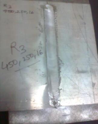
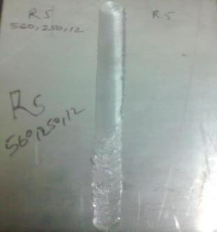
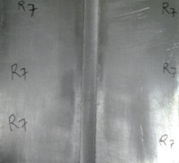
After performing the welding, only three welding runs [i.e.R1( 450-80-8), R4( 560-160-8) and R7 (710-225-8)] were produce good quality weld and other then these run generating more heat which causes sticking between specimen and backing plate which is undesirable and showninfiger.3.5.
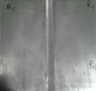
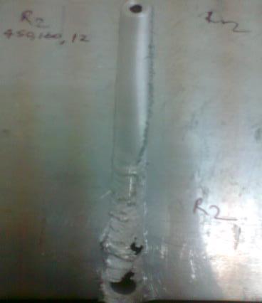
R1(450-80-8) R2(450-160-12)
R3(450-225–16)
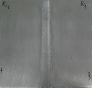
R4(450-160-8) R5(560-250-12) R7(560-80-16)
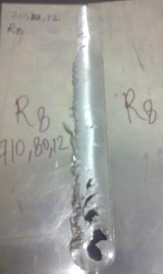
R8(710-80-12))
Fig.3.5Weldsampleswithdifferentprocessparameters (R1,R2,R3,R4,R5,R7andR8)
All weld samples are shown above in fig 3.6. Equation 2.1 showsthatathighertoolpindiameter,highertoolrotation and less welding speed causes the heat generation is high which is clearly shown in above figure 3.6 (R2, R3, R5 and R8). High heat generation causes more amount of material flash out during welding and sticking between strips and backingplate, whichis undesirable.R6 (560 - 80- 16) and R9(710 - 160- 16)arenot possible becauseofhighertool diameteralongwithlowerweldingspeed.R1(450-80-8), R4 (560 - 160 - 8) and R7 (710 - 250 - 8) were produces goodqualityweldsasshowninfigure3.6(R1,R4andR7).
2024, IRJET | Impact Factor value: 8.226 | ISO 9001:2008
International Research Journal of Engineering and Technology (IRJET) e-ISSN:2395-0056
Volume: 11 Issue: 08 | Aug 2024 www.irjet.net
Varioustestswillbeperformedonbasematerialaswellas weldmaterialsuchas...
3.4.2 Tensile test
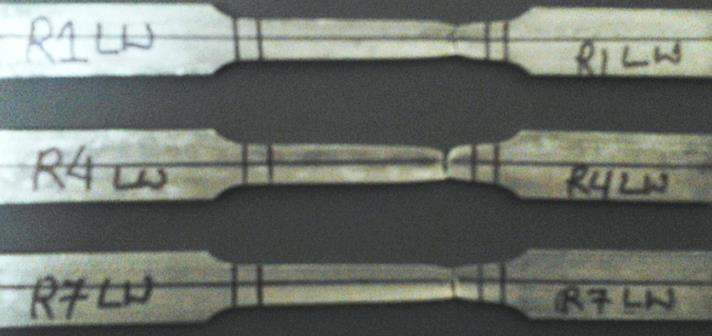
TheweldsampleswerecutbywireEDMalongtheweld.In this experiment uniaxial tensile test was performed for eachsample.Inthistestmechanicalpropertiesi.e.ultimate strength, yield strength and % elongation were obtained The uniaxial tensile test is known as a basic and universal engineering test to achieve material parameters such as ultimate strength, yield strength, % elongation, % area of reduction and Young’s modulus. These important parameters obtained from the standard tensile testing are useful for the selection of engineering materials and welds for any applications required. Tensile test will be carried out in transverse as well as in longitudinal direction to check the weakest region of the weld and the strength of theweldzone.Twotensiletestsampleswillbepreparedin each weld run which are taken from weld samples as showninfig3.7and3.8.
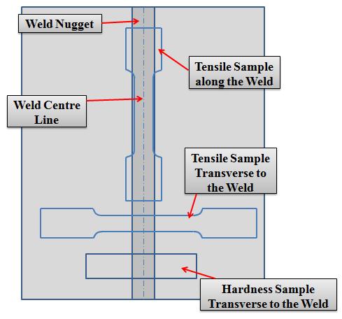


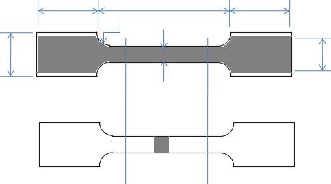


3.8 SubsizespecimensusedintensiletestsofTWBs(a) longitudinalspecimen(b)transversespecimen
3.4.2.1 Yield Strength (YS), Ultimate tensile Strength (UTS), Ductility
Theyieldstresswasobtainedusingthe0.2%offsetmethod. UTSweredeterminedusingthemaximumloadandoriginal cross section area of specimen. The percentage elongation orthe reduction in cross sectionarea isusedasa measure of ductility of material. Percentage elongation was calculated at the fracture. The elongation was found by measuring the final gauge length after fitting together the fracturedspecimen.
The result and observations obtained from various experiment (i.e. uniaxial tensile tests, microhardness tests, formabilitytestsonparentsandtailorweldedblanks).
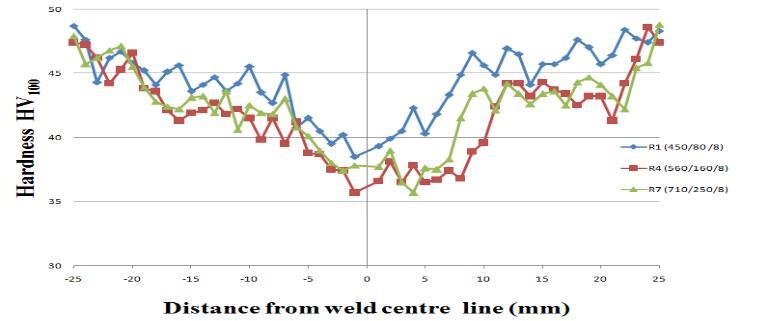
Fig. 4.1 MicrohardnessprofileacrosstheweldinTWBs samples
International Research Journal of Engineering and Technology (IRJET) e-ISSN:2395-0056
Volume: 11 Issue: 08 | Aug 2024 www.irjet.net p-ISSN:2395-0072
4.2 Tensile tests
SubsizespecimenofTWBs wastestedinbothlongitudinal andtransverse direction. Transversetests wereperformed tocheckthestrengthofthe weldregionandtoensurethat weld parameters chosen in FSW welding are optimum. Failure occurred on the weld nugget zone because in this region thickness of the joint reduces due to plastic flow of metalacrosstheweldmovementdirectionwhichisknown as flash. The fractured specimen of base metal, transverse and longitudinal tensile tests of weld region are shown in fig4.3.
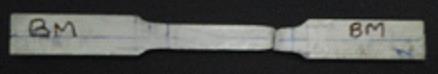
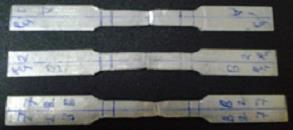
(c)
Fig 4.2 Fracturespecimenintensiletests(a)basematerial (b)across/transversetotheweld(c)along/longitudinalto theweld
Thestandardtensileproperties0.2%offsetyieldstrength; ultimate strength and % elongation of base metal, transversetotheweldandlongitudinaltotheweldforeach rundeterminedfromtensiletestsaregivenintable4.2.
Table 4.2 Mechanicalpropertiesofbasemetalandweld metal.
Run
Fromtheabovetable,itcanbeobservedthatyieldstrength and ultimate tensile strength of weld (i.e. longitudinal direction / along the weld (LW) and transverse direction/ across the weld (TW)) is less than the base metal but percentage elongation of weld metal is greater than base metal in both cases (i.e. longitudinal and transverse direction).Itcanbealsoobservedthatincaseoftransverse and longitudinal weld, percentage elongation of longitudinal weld is greater than transverse weld but the strengthyieldstrengthandultimatetensilestrengthofboth the weld (i.e. longitudinal and transverse direction) are nearlyequal.
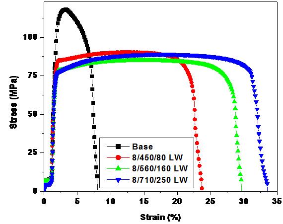
4.3 (a) Stress v/s straindiagramoflongitudinaldirection foreachrunalongwithbasemetal
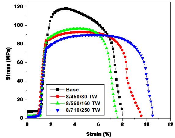
Fig 4.3 (b) Stress v/s straindiagramoftransversedirection foreachrunalongwithbasemetal
Above result can be verified with the stress – strain curve shown in fig 4.3 (a) and (b). Form the curve it can be also observedthatR1(450/80/8)givesbetterstrengthandless percentage elongation but as increase in tool rotation
International Research Journal of Engineering and Technology (IRJET) e-ISSN:2395-0056
Volume: 11 Issue: 08 | Aug 2024 www.irjet.net p-ISSN:2395-0072
(rpm),thepercentageelongationincreases.Fromtheabove curve R7 (710/250/8) gives good strength and ductility as comparetotheothers.
The following conclusions can be drawn from the results:
(1) Friction stir welding process was used to join the AA-1100 sheets. It is concluded from above result the optimum range of tool rotation (rpm) is 450 rpm to 710 rpm. If it is less than 450rpm, due to less heat generation joint produced by FSW is not good but if it is more than 710 rpm flushing takes place.
(2) At a constant rotational speed, an increase in the travel speed leads to wormhole initiation near the bottom of the weld. Furthermore, the size of the wormholesincreaseswiththetravelspeedbecause ofinadequatematerial flow towardsthe bottomof theweld.
(3) Tensile tests were performed to find out the mechanical properties of the AA 1100 sheets as well as weld region (i.e. longitudinal and transverse direction) of TWBs. It was observed that the % elongation of weld in longitudinal directionisveryhighascomparetobasemetal.
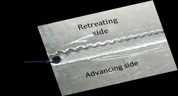
(4) Hardness in advancing side is more than the retreating side in HAZ because the grain refinement is more in advancing side than retreatingside.
SCOPE FOR FUTURE WORK
(1) FSW tool with pin can also be used for further study.
(2) Microstructure of the weld can also be seen for betterunderstandingandanalyzedthemforbetter weldingcharacteristics.
1. R. Nandan ,T. DebRoy ,H.K.D.H. Bhadeshia, Recent advances in friction-stir welding – Process, weldment structure and properties, Progress in MaterialsScience53(2008)980–1023.
2. J. Jeswiet, M. Geiger, U. Engel, M. Kleiner, M. Schikorra, J. Duflou, R. Neugebauer, P. Bariani, S. Bruschi, Metal forming progress since 2000, CIRP JournalofManufacturingScienceandTechnology1 (2008)2–17.
3. Amir Abbas Zadpoor, Jos Sinke, Rinze Benedictus, Raph Pieters, Mechanical properties and microstructure of friction stir welded tailor-made blanks, Materials Science and Engineering A 494 (2008)281290.
4. Sushanta Kumar Panda, D. Ravi Kumar, Improvementinformabilityoftailorweldedblanks by application of counter pressure in biaxial stretch forming, journal of materials processing technology204(2008)70–79.
5. R Ganesh Narayanan1 and K Narasimhan, Predicting the forming limit strains of tailorweldedblanks,Themanuscriptwasreceivedon17 April 2008 and was accepted after revision for publicationon20June2008.
6. M.Sivashanmugam, S.Ravikumar, T.Kumar, V.Seshagiri Rao, D.MuruganandamA Review on Friction Stir Weldingfor AluminiumAlloys,978-14244-9082-0/10/$26.00©2010IEEE
7. D.M. Rodrigues, A. Loureiro, C. Leitao, R.M. Leal, B.M. Chaparro, P. Vilaça, Influence of friction stir welding parameters on the microstructural and mechanical properties of AA 6016-T4 thin welds, MaterialsandDesign30(2009)1913–1921.
8. Wonoh Lee, Kyung-Hwan Chung, Daeyong Ki, Junehyung Kim, Chongmin Kim, Kazutaka Okamoto, R.H. Wagoner, Kwansoo Chung, Experimental and numerical study on formability of friction stir welded TWB sheets based on hemispherical dome stretch tests, International JournalofPlasticity25(2009)1626–1654.