
International Research Journal of Engineering and Technology (IRJET) e-ISSN:2395-0056
Volume: 11 Issue: 08 | Aug 2024 www.irjet.net p-ISSN:2395-0072

International Research Journal of Engineering and Technology (IRJET) e-ISSN:2395-0056
Volume: 11 Issue: 08 | Aug 2024 www.irjet.net p-ISSN:2395-0072
Sumer Singh
Introduction- Incurrentautomotivestampingtechnology,
there are two basic paths that can be followed to arrive at the final panel. The first method is part disintegration. In this technique, each different section of the blank is stamped separately and then spot welded together in the shape of the final part. This method has numerous advantage such as the ability to select the specific properties,i.e. thestrength, thickness,corrosion resistance etc of each area of the blanks. This method also gives a higher yield ratio of material used. However, this method has some disadvantage. The major problem is the large numberofdifferentformingoperationsthatisrequiredfor the disintegration method, which translate to high tooling costs. Also assembly costs would increase (more joining required) and there is possibility of fittability problem betweenthedifferentstamping.Theotherpossiblemethod is the integration method. In the integration method, the part is stamped out of a single blank. This reduces the number of tools needed; the assemblies cost and eliminate the fittability problem. However, the design engineer is forced to work same grade, thickness, strength and corrosionresistancethroughouttheentirepart;thiswould increasethecostandweightofthepartsignificantly.
In the present work the TWBs made by FSW process and studytheeffectofprocessparameteronweldquality.
1.1 Friction Stir Welding Setup: The following were used for the Friction Stir Welding ProcessofAluminiumalloysheets.
1. VerticalMillingmachine
2. Fixture
3. BackingPlate
4. Tool
5. Specimen
1. Fixture: A fixture is a work-holding or support device used in various manufacturing processes. The main purpose of a fixture is to locate and in some cases hold a workpiece during a machining operation
Table 1.1 FSWtooldimensions.


2. Backing Plate: Aplateofdimensions200x100x10mm was firstly cut by hacksaw machine then machined on shaper in order to reduce the thickness to 8 mm and later the finishing process was carried out on surface grinding machine.Theflatnessofthebackingplateisacrucialfactor inordertoperformtheexperimentcorrectly.
International Research Journal of Engineering and Technology (IRJET) e-ISSN:2395-0056
Volume: 11 Issue: 08 | Aug 2024 www.irjet.net p-ISSN:2395-0072
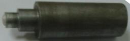
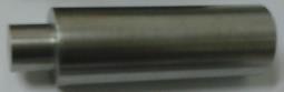
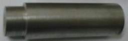
3 Tool: Aroundbarofdiameter25mmandlength75mm of EN31 [isa highcarbonalloysteel whichachievesa high degreeofhardnesswithcompressivestrengthandabrasion resistance.] was machined on lathe to produce a tool. The finaldimensionsofthetoolwere
4.Specimen: Aluminium alloy sheets of thickness 1.7 mm werecutintostripsofdimension170x52mminshearing machine. Firstly, 30 strips of above dimensions were cut and later machined on shaper on the edge to be welded in ordertogetco-aligningofspecimens.
1.2 Welding procedure
In trail experiment four different speeds with constant shoulderdiameter,weldspeedanddepthofplungingwere selected for the study as shown in table 3.2. The rolling directionofthesheetwasinparallelwiththewelding.Prior to the welding, the edge of the strips was machined in shaper machine. Firstly, the finished edges of two specimens were brought into contact and specimens were placedonthebackingplate.Thentheywereclampedusing fixtures
Table 1.2 Process parameters taken for trail experiment
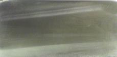
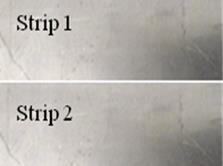
The welding was carried out by using the selected variations as shown in table 3.2. By continuous visual inspection evaluate the quality of welds. Three welds of each variation were prepared. All weld specimen shown belowfig.3.5
All weld samples are shown above in fig 3.5. Equation 2.1 showsthatathigherrotationalspeedtheheatgenerationis high which is clearly shown in above figure 3.5 c, d. High
heat generation causes more amount of material flash out during welding and less heat generation causes improper bonding between strips, which is undesirable. Therefore optimumrangeofspeed,whichwasusedinthisexperiment, is in between 450 rpm to 710 rpm. Common defects in friction stir welds include porosity and surface defects [1]. Common defects in friction stir welds include porosity and surface defects [1]. At a constant rotational speed, an increase in the travel speed leads to wormhole initiation near the bottom of the weld. Furthermore, the size of the wormholes increases with the travel speed because of inadequate material flow towards the bottom of the weld. There are indications that the travel speed to rotational speedratioisanimportantvariableintheformationofthe wormholedefect.Forthesamematerialandtoolgeometry, a high ratio tends to favor the formation of wormhole defects. That’s why it was restricted f Most of the heat generation occurs at the interface between the tool shoulder and the work–piece. Significant heterogeneity in heat generation at that interface can lead to defect formation in the form of excess flash due to surface overheating.
The quality of FSW welds is greatly dependent on the selection of process parameters such as welding speed (mm/min), rotation speed (rpm) and tool diameter. Since the heat generation [eq. 2.1] in weld nugget zone plays an importantroleindeterminingthemechanicalpropertiesof the weld. Therefore, it is very important to select the welding process parameters for obtaining optimal heat in the weld nugget zone. In the welding was carried out by using the selected variations of parameters as shown in Table1 which is obtained by Taguchi’s orthogonal array method. The Taguchi method involves reducing the variationinaprocessthroughrobustdesignofexperiments. The experimental design proposed by Taguchi involves using orthogonal arrays to organize the parameters affectingtheprocessandthelevelsatwhichtheyshouldbe varies. Instead of having to test all possible combinations like the factorial design, the Taguchi method tests pairs of combinations. This allows for the collection of the necessary data to determine which factors most affect product quality with a minimum amount of experimentation,thussavingtimeandresources. Primarily visual inspection evaluate the good quality of welds were obtainsbyFSW.Fourweldsweredevelopingoneachsetof parameters.
International Research Journal of Engineering and Technology (IRJET) e-ISSN:2395-0056
Volume: 11 Issue: 08 | Aug 2024 www.irjet.net p-ISSN:2395-0072
Table 2.2 Process parameters
Weldin g
1
3
4 560 160 8 0.35 Good
5 560 250 12 0.35 Poor/ over heating
6 560 80 16 0.35 Not possible due to over heating
7 710 250 8 0.35 Good
8 710 80 12 0.35 Poor/ over heating 9 710 160 16 0.35 Not possible due to over heating
After performing the welding, only three welding runs [i.e.R1( 450-80-8), R4( 560-160-8) and R7 (710-225-8)] were produce good quality weld and other then these run generatingmoreheatwhichcausesstickingbetween
2.4 Mechanical Properties
Varioustestswillbeperformedonbasematerialaswellas weldmaterialsuchas...
2.4.1 Microhardness tests
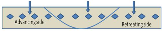
Metallographic sample were cut from the transverse direction of weld and mounting were prepared by epoxy resign. Samples were polished with different grade of emery paper starting from 200 to 2000 and then soft polishing on cloth with alumina Powder (Al2O3) with I, II and III grades having particle size 5, 3 and 1 µm respectively. Subsequently samples were etched with Killer’s reagent having 2.5 % HNO3, 1.5 % HCl and 1 % HF and 95 % water (by volume). Vicker’s hardness test was performed in each sample in transverse direction of weld covering advancing side, weld and retreating side. The hardness of a material usually is considered resistance to permanentindentation.Theindentationloadwastaken100
grams for a 10 sec dwell time. Microhardness test samples will be prepared in each weld run which are taken from weld specimen across the weld, which is cover the entire weld region (i.e. weld nugget zone and heat affected zone) asshowninfig3.6.


2.4.2 Tensile test
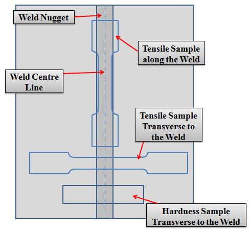
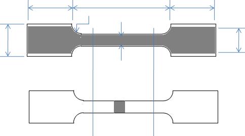
TheweldsampleswerecutbywireEDMalongtheweld.In this experiment uniaxial tensile test was performed for eachsample.Inthistestmechanicalpropertiesi.e.ultimate strength, yield strength and % elongation were obtained. The uniaxial tensile test is known as a basic and universal engineering test to achieve material parameters such as ultimate strength, yield strength, % elongation, % area of reduction and Young’s modulus. These important parameters obtained from the standard tensile testing are useful for the selection of engineering materials and welds for any applications required. Tensile test will be carried out in transverse as well as in longitudinal direction to check the weakest region of the weld and the strength of theweldzone.Twotensiletestsampleswillbepreparedin each weld run which are taken from weld samples as showninfig3.7and3.8.
International Research Journal of Engineering and Technology (IRJET) e-ISSN:2395-0056


2.4.2.1 Yield Strength (YS), Ultimate tensile Strength (UTS), Ductility
Theyieldstresswasobtainedusingthe0.2%offsetmethod. UTSweredeterminedusingthemaximumloadandoriginal cross section area of specimen. The percentage elongation orthe reduction in cross sectionarea isusedasa measure of ductility of material. Percentage elongation was calculated at the fracture. The elongation was found by measuring the final gauge length after fitting together the fracturedspecimen.
The result and observations obtained from various experiment (i.e. uniaxial tensile tests, microhardness tests, formabilitytestsonparentsandtailorweldedblanks).
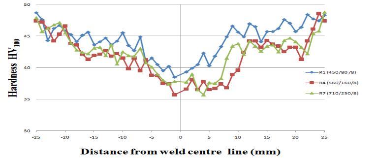
The microhardness analysis revealed that the average width of weld zone (weld nugget zone and heat affected zone)isapproximately3to4mmbothsidehigherthanthe weld nugget zone (i.e. 14 mmfor 8mm diametertool). The hardness profiles of all weld configurations are shown in Fig 4.1. Clearly shown is that welding has created a highly heterogeneoushardnessdistribution.Fromtheliterature,it hasbeenwidelyacceptedthatthesofteningeffectofFSWis due to dissolution and/or coarsening of the precipitates. Furthermore, the hardness profile is asymmetric for all configurations. Generally, the sheet at the advancing side hasahigherhardnesscomparedtotheoneattheretreating side, which has been observed in other studies as well,
Volume: 11 Issue: 08 | Aug 2024 www.irjet.net p-ISSN:2395-0072 © 2024, IRJET | Impact Factor value: 8.226 | ISO 9001:2008
resulting from different deformations at both sides. The materialattheadvancingsideisinfluencedmoreandfora longer time by the vortex velocity field because they have different directions on the retreating side but the same direction on the advancing side. Therefore, the straining andgrainrefinementismoresevereontheadvancingside.
Table 3.1 VickersHardnessvaluesofallsampleswith respecttoweldregion
from Centre Line
International Research Journal of Engineering and Technology (IRJET) e-ISSN:2395-0056
Volume: 11 Issue: 08 | Aug 2024 www.irjet.net p-ISSN:2395-0072
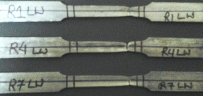
SubsizespecimenofTWBs wastestedinbothlongitudinal andtransverse direction. Transversetests wereperformed tocheckthestrengthofthe weld regionandtoensurethat weld parameters chosen in FSW welding are optimum. Failure occurred on the weld nugget zone because in this region thickness of the joint reduces due to plastic flow of metalacrosstheweldmovementdirectionwhichisknown as flash. The fractured specimen of base metal, transverse and longitudinal tensile tests of weld region are shown in fig4.3.
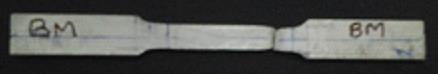
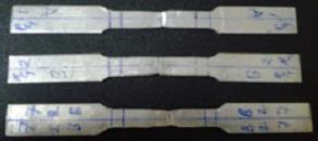
4.1 Fracturespecimenintensiletests(a)basematerial (b)across/transversetotheweld(c)along/longitudinalto theweld
Thestandardtensileproperties0.2%offsetyieldstrength; ultimate strength and % elongation of base metal, transversetotheweldandlongitudinaltotheweldforeach rundeterminedfromtensiletestsaregivenintable4.2.
Table 4.2 Mechanicalpropertiesofbasemetalandweld metal.
Fromtheabovetable,itcanbeobservedthatyieldstrength and ultimate tensile strength of weld (i.e. longitudinal direction / along the weld (LW) and transverse direction/ across the weld (TW)) is less than the base metal but percentage elongation of weld metal is greater than base metal in both cases (i.e. longitudinal and transverse direction).Itcanbealsoobservedthatincaseoftransverse and longitudinal weld, percentage elongation of longitudinal weld is greater than transverse weld but the strengthyieldstrengthandultimatetensilestrengthofboth the weld (i.e. longitudinal and transverse direction) are nearlyequal.
International Research Journal of Engineering and Technology (IRJET) e-ISSN:2395-0056
Volume: 11 Issue: 08 | Aug 2024 www.irjet.net p-ISSN:2395-0072
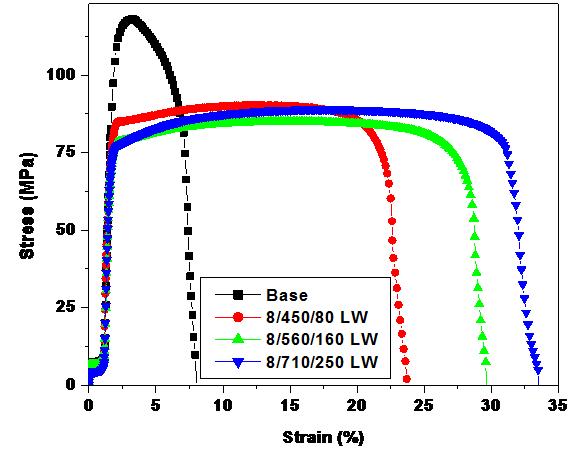
4.3 (a) Stress v/s straindiagramoflongitudinaldirection foreachrunalongwithbasemetal
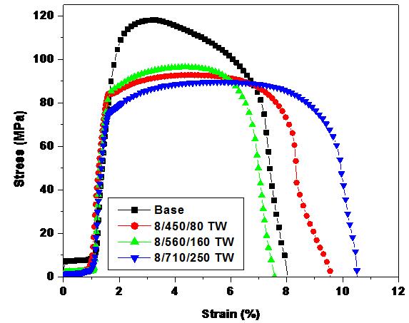
4.3 (b) Stress v/s straindiagramoftransversedirection foreachrunalongwithbasemetal
Above result can be verified with the stress – strain curve shown in fig 4.3 (a) and (b). Form the curve it can be also observedthatR1(450/80/8)givesbetterstrengthandless percentage elongation but as increase in tool rotation (rpm),thepercentageelongationincreases.Fromtheabove curve R7 (710/250/8) gives good strength and ductility as comparetotheothers.
CONCLUSION AND SCOPE FOR FUTURE WORK
The following conclusions can be drawn from the results:
(1) Friction stir welding process was used to join the AA-1100 sheets. It is concluded from above result the optimum range of tool rotation (rpm) is 450 rpm to 710 rpm. If it is less than 450rpm, due to less heat generation joint produced by FSW is not
good but if it is more than 710 rpm flushing takes place.
(2) At a constant rotational speed, an increase in the travel speed leads to wormhole initiation near the bottom of the weld. Furthermore, the size of the wormholesincreaseswiththetravelspeedbecause ofinadequatematerial flow towardsthe bottomof theweld.
(3) Tensile tests were performed to find out the mechanical properties of the AA 1100 sheets as well as weld region (i.e. longitudinal and transverse direction) of TWBs. It was observed that the % elongation of weld in longitudinal directionisveryhighascomparetobasemetal.
(4) Hardness in advancing side is more than the retreating side in HAZ because the grain refinement is more in advancing side than retreatingside.
FOR FUTURE WORK
(1) FSW tool with pin can also be used for further study.
(2) Microstructure of the weld can also be seen for betterunderstandingandanalyzedthemforbetter weldingcharacteristics.
1. R. Nandan ,T. DebRoy ,H.K.D.H. Bhadeshia, Recent advances in friction-stir welding – Process, weldment structure and properties, Progress in MaterialsScience53(2008)980–1023.
2. J. Jeswiet, M. Geiger, U. Engel, M. Kleiner, M. Schikorra, J. Duflou, R. Neugebauer, P. Bariani, S. Bruschi, Metal forming progress since 2000, CIRP JournalofManufacturingScienceandTechnology1 (2008)2–17.
3. Amir Abbas Zadpoor, Jos Sinke, Rinze Benedictus, Raph Pieters, Mechanical properties and microstructure of friction stir welded tailor-made blanks, Materials Science and Engineering A 494 (2008)281290.
4. Sushanta Kumar Panda, D. Ravi Kumar, Improvementinformabilityoftailorweldedblanks by application of counter pressure in biaxial stretch forming, journal of materials processing technology204(2008)70–79.
5. R Ganesh Narayanan1 and K Narasimhan, Predicting the forming limit strains of tailorweldedblanks,Themanuscriptwasreceivedon17
International Research Journal of Engineering and Technology (IRJET) e-ISSN:2395-0056
Volume: 11 Issue: 08 | Aug 2024 www.irjet.net p-ISSN:2395-0072
April 2008 and was accepted after revision for publicationon20June2008.
6. M.Sivashanmugam, S.Ravikumar, T.Kumar, V.Seshagiri Rao, D.MuruganandamA Review on Friction Stir Weldingfor AluminiumAlloys,978-14244-9082-0/10/$26.00©2010IEEE
7. D.M. Rodrigues, A. Loureiro, C. Leitao, R.M. Leal, B.M. Chaparro, P. Vilaça, Influence of friction stir welding parameters on the microstructural and mechanicalpropertiesofAA
© 2024, IRJET | Impact Factor value: 8.226 | ISO 9001:2008 Certified Journal | Page182