
International Research Journal of Engineering and Technology (IRJET) e-ISSN: 2395-0056
Volume: 11 Issue: 08 | Aug 2024 www.irjet.net p-ISSN: 2395-0072

International Research Journal of Engineering and Technology (IRJET) e-ISSN: 2395-0056
Volume: 11 Issue: 08 | Aug 2024 www.irjet.net p-ISSN: 2395-0072
Mr. R.R Badeghar1 , Mr. Apurvachandra A Patil2
1 Assistant Professor, Department of Civil Engineering, Sinhgad Institute of Technology, Solapur, Maharashtra, India
2 PG Student, Department of Civil Engineering, Sinhgad Institute of Technology, Solapur, Maharashtra, India
Abstract - Multistory buildings are subjected to various environmental factors, among which thermal loads play a significant role. Changes in temperature can induce stress, strain, and deformation in structural elements, potentially compromising the integrity and safety of the building. Despite the growing construction ofhigh-rise buildings inurbanareas, there is limited understanding of how varying and uniform thermal loads affect different building heights. This research aims to address the structural response ofmultistory buildings subjected to thermal loads by using Staad Pro simulation software. Specifically, it focuses on the thermal analysis of G+10, G+15, and G+20 buildings under different temperature load conditions, examining the impact of both varying and uniform thermal loads on the structural behavior. Moreover, it seeks to analyze the influence of uniform temperature forces on buildings of varying heights in compliance with Indian codal provisions. Identifying the critical thermal responses in these buildings will help in designing safer and more resilient structures. The objectives of current research are to evaluate the structural response of multistory building subjected to thermal loads using Staad Pro simulation software. The thermal analysis of G+10 building is conducted with varying temperature loads. The thermal analysis of G+15 building is conducted with uniform temperature loads. The thermal analysis of G+20 buildingwith uniform temperature loads. The story drifts at G+10, G+15, and G+20 levels are significantly within the permissible limits set by IS 1893:2016.
Key Words: Thermal analysis, story drift, multi-story
Reinforced concrete structures possess inherent vulnerabilitytothermalloadscausedbyfactorssuchasfire, heatofhydration,servicefunction,andotherunavoidable conditions.Thedesignofthestructuremustconsiderthese loadings, as they may sometimes act as the main loading condition [1]. The prolonged duration of the construction process leads to the exposure of different structural componentstovaryingtemperatures.Thethermalvariations that cause displacements and stresses in a structure are separate from the temperatures experienced during installationandconstruction,whichareoutsidethecontrol ofthedesigner.Thedesigntemperaturechangeisavariable
thatcanpotentiallyimpacttemperaturefluctuationswithin buildings.Thisreferstothetemperaturedifferencebetween the construction phase and the highest or lowest temperature of the summer or winter [2, 3]. The second elementthatisaccessibleistemperaturecontrol[1,3].The third component refers to the geometric system, proportions, and type of foundation connection of the buildings[1,3].Theultimatefactortobetakenintoaccount during the construction of the structure is the choice of constructionmaterials[1,3].Multiplefactorscontributeto the fluctuations in temperature change and temperature gradientobservedamongdifferentcountries.Consequently, theuseofdifferentcodesleadstovariationsintemperature gradientsacrossdifferentcountries[4-7]
Prakarshet.al.[8]Incertaincountries,steel buildingsare not frequently employed. Steel-concrete composite constructionsarerequiredinmajorurban centerssuchas Delhi, Mumbai, and Bangalore due to the absence of horizontalexpansion.Compositeconstructionisextensively employed,andthesteelindustryisexperiencingaccelerated growth in nearly every country on the planet. The three primaryfactorsofuttermostimportancefromastructural perspectivearefinancialresources,constructionduration, and structural integrity. In comparison to RCC structures, steelframeworkswithinfilldemonstratean8%increasein maximumstoreydisplacement.
Sattainathanet.al.[9]IncontrasttoRCCconstructions,the steel-concretecompositetechnologyhasgainedpopularity inthisinvestigation.Severalengineersfindthecomplexityof analysis and design to be a challenge. Steel-concrete compositeconstructionisthepreferredmethodduetoits numerousbenefitsovertraditionalbuildingmethods.Steelconcrete systems offer cost-effective structural solutions that are highly durable, efficient to construct, and exhibit exceptional seismic performance, as indicated by the findings. The utilization of steel-to-concrete ratios is advantageousforcompositestructures.
Bhavin et. al. [10] Concrete is a prevalent construction material in India, particularly for medium- and low-rise
International Research Journal of Engineering and Technology (IRJET) e-ISSN: 2395-0056
Volume: 11 Issue: 08 | Aug 2024 www.irjet.net p-ISSN: 2395-0072
projects. In addition, steel is frequently employed in the construction of lofty structures. Although composite constructionislesscommon,itisfeasiblethatitwill offer supplementary advantages for medium- and high-rise structures. It is feasible to implement steel-concrete composite construction as an alternative to RCC constructionsinordertooptimizethebenefitsofsteeland concreteandestablishcost-effectiveandefficientstructures. Thecontractororownerisresponsiblefordeterminingthe essentialattributesinthefield,andtheymaysubsequently selecttheappropriatematerial.
MohdAmirKhan[11]Thisstudyinvestigatestheadvantages andcharacteristicsofstructuralsteel-concretecomposites, whichoffera morecost-effectivealternative toreinforced concrete buildings and facilitate the construction of foundations.Structuralframeworksthatexhibitexceptional combinationsofpropertiesdemonstrateincreasedlevelsof strength.IncomparisontoRCCframes,compositestructural frames exhibit superior resistance to lateral stresses. Compared to an RCC frame, the Steel-Concrete Composite framedemonstratesareducedoverturningmomentandless lateraldisplacement.
GorakhVinit[12]Thisarticleexploresthemethodologyof designing and analyzing multistory structures using the widely acknowledged STAAD.pro software. ISMB sections areutilizedtoconstructthejoistsinthiscase.Thesystem createsastrongandlong-lastingnetworkthatcanefficiently beartheloadoftheslab.Wideflangesectionsareutilizedin columndesignbecauseoftheirsuperiorloadtransformation capabilities and their strong resistance to buckling and warping.
Jyothi et. al. [13] The steel construction exhibits higher resistancecomparedtotheRCCstructure,asevidencedby the findings of the paper. When comparing steel constructionstoRCCstructures,itcanbeobservedthatsteel constructionshaveareduceddeadweight.Thisreductionin deadweightresultsinadecreaseinshearforceandbending moment.Steelstructuralmembersdemonstrateafavorable strength-to-massratio.Steelstructuralcomponentspossess a high level of density, resulting in an enhanced aesthetic appealfortallstructuresandareductioninthenecessary constructionarea.
Pauloet.al.[14]Thethermalperformanceofsteel-decked compositepaversisexaminedinthisstudyundercontrolled test conditions that simulate a fire starting at the base. A layer of concrete is applied onto the surface of a steel structure in this solution. Steel mesh or individual reinforcingbars,commonlyknownasrebars,arecommonly used to enhance the strength and durability of concrete structures. Furthermore, the deck is susceptible to unintentionalignitionoriginatingfromthelowerregion.All varieties of structures require the implementation of this
compositesolutiontoachievefireresistanceandadhereto regulatoryandspecificationrequirements.
Pallaviet.al.[15] Accordingtoresearch,steelisacommonly used construction material in the building of multi-level commercialstructures,factories,andbridges.Bothsteeland concretepossessexcellentadhesivepropertiesandprovide rapidconstruction.Thetwomaterials,whichexhibitdistinct differences,functionsynergisticallyandenhanceeachother. Anobjectconsistingofacompositestructuremadeofsteel and concrete exhibits nearly identical thermal expansion whenintransit.Comparedtostructuresthatconsistsolelyof steel or reinforced concrete, this approach is more economicallyefficient.Thetotalweightoftheconcreteand steelstructureislowercomparedtothatofthereinforced concrete construction due to the reduced amount of structuralsteelused.
The objectives of current research are to evaluate the structural response of multistory building subjected to thermalloadsusingStaadProsimulationsoftware.Thermal analysisofG+10buildingwithvaryingtemperatureloads. Thermal analysis of G+15 building with uniform temperatureloads.ThermalanalysisofG+20buildingwith uniformtemperatureloads.
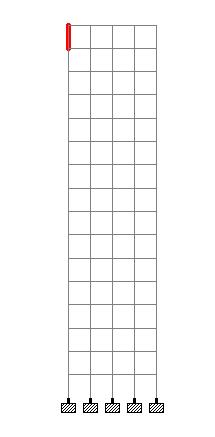
Definethecoordinatesystemandinputthenodecoordinates that represent the joints of the structure. Connect these nodes with members to form beams, columns, and other structuralelements.Assignthecorrectcross-sectionaland materialproperties,ensuringthemodelaccuratelyreflects thephysicalcharacteristicsofthestructure.
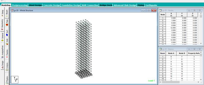
Figure 1: Modeling of nodes and wireframe model
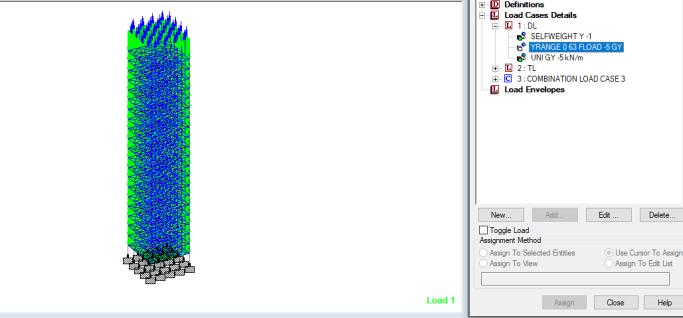
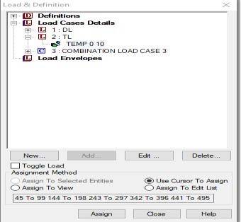
Identifyanddefinevariousloadcasesthatthestructurewill encounter.Theseincludedeadloadssuchastheself-weight ofstructuralelementsandfixedequipment,liveloadslike occupancyandmovablefurniture,andenvironmentalloads suchaswind,seismic,andsnowloads.Eachloadcaseshould bedefinedseparatelytoaccuratelyreflectitsimpactonthe structure.
International Research Journal of Engineering and Technology (IRJET) e-ISSN: 2395-0056
Volume: 11 Issue: 08 | Aug 2024 www.irjet.net p-ISSN: 2395-0072
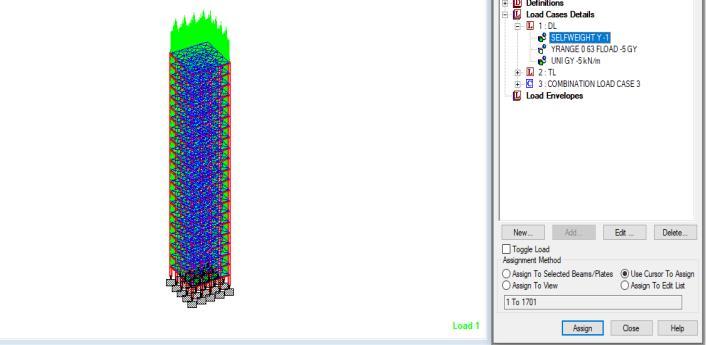
3: Self weight applied on the structure
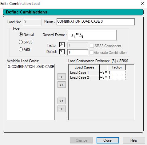
Figure 4: Load combination
Create load combinations to simulate realistic scenarios where multiple loads act simultaneously. These combinations should adhere to design codes (e.g., AISC, Eurocode)andconsiderthemostunfavorableconditionsthe structuremightface.Properloadcombinationsarevitalfor assessingthestructure'ssafetyandperformance.Inthe2nd case, all the stories of building are applied with 100C temperaturemagnitudeasshownbyfigure5
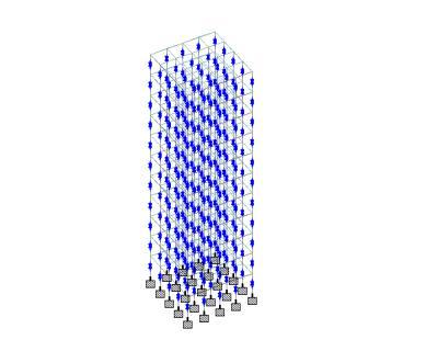
5.
AND DISCUSSION
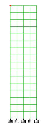
The results of deformation, floor stresses and bending moment are obtained for G+10 building wherein all the storiesareappliedwith100Ctemperature. Fordetermining deformation,thetopmostnodeisselectedasshowninfigure 6
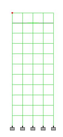
Figure6:Topnodedeformation
Table1:Nodaldeformationdata
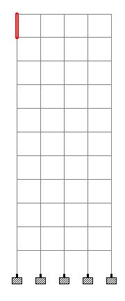
With the thermal loads applied on all the floors, the maximum induced deformation is 11.041mm. The beam deformationisobtainedasshowninfigure7.The1st floor beamisselectedandthemaximumdeformationobtainedis 0.188m.
International Research Journal of Engineering and Technology (IRJET) e-ISSN: 2395-0056
Volume: 11 Issue: 08 | Aug 2024 www.irjet.net p-ISSN: 2395-0072
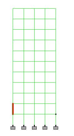
From the analysis, the maximum deformation on selected beamis0.221mm.Theparabolicdeflectionshapeconfirms thatthebeamisexperiencingbendingduetoasymmetrical load.Themaximumdeflectionatthemid-span(0.002mm)is minimal,indicatingthatthebeamisdesignedtobeverystiff and capable of handling the applied load with minimal deformation. The equal deflection at the supports (0.001 mm) indicates symmetrical loading and possibly equal supportstiffness.Thissymmetryandminimaldeflectionalso suggest that the load is uniformly distributed or centrally placed,whichisatypicalscenarioforstructuralanalysis.
8:
Thedeflectionshapeconfirmsthatthebeamisexperiencing bendingduetoasymmetricalthermalload.Themaximum deflectionatthemid-span(0.234mm)isminimal,indicating that the beam is designed to be very stiff and capable of handlingtheappliedloadwithminimaldeformationatthe giventhermalloads.
9:
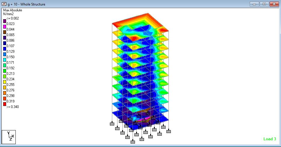
The lower stress distribution around the central core suggestsitplaysacrucialroleintheoverallstabilityofthe building.Thecorelikelyhousesessentialstructuralelements likeshearwallsorelevatorshafts,contributingsignificantly tothebuilding'slateralstability.Thelowerstresslevelsin thebottomfloorsaretypical,asthesefloorsareclosertothe foundationandprimarilycarrycompressiveloadsfromthe upper structure. This indicates that the foundation and lower floors are well-designed to handle the cumulative loadswithoutexperiencinghighstressconcentrations.The plotshowshigherabsolutepressureatthecornersofeach platewithmagnitudeofmorethan0.319N/mm2
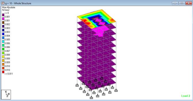
Themaximumabsolutepressureplotonbuildingisshownin figure 10. Due to thermal load, the maximum pressure is induced on top plate with magnitude of more than .010 N/mm2 Themaximumdeformationisobtainedatthetopof G+15buildingwhereinthemaximuminduceddeformationis nearly11.163mm.Thecombinationofloadhas11.119mm deformation.
International Research Journal of Engineering and Technology (IRJET) e-ISSN: 2395-0056
Volume: 11 Issue: 08 | Aug 2024 www.irjet.net p-ISSN: 2395-0072
11:NodaldeformationofG+15building
The topmost beam is selected for determining beam parameters as shown in figure 11. The maximum deformationontopmostbeamelementis0.622.Theinduced deformationatthe1st pointofbeamis0.182mmandatthe endpointis0.273mm.
Table2:Nodaldeformationdata
12:
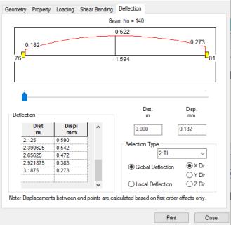
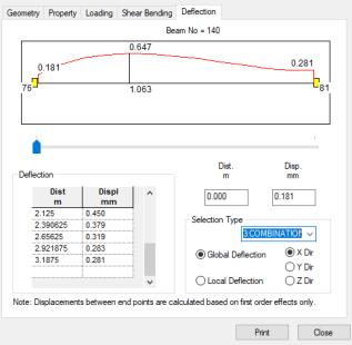
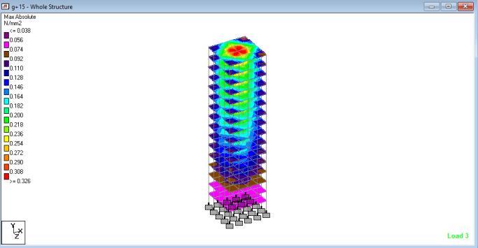
Figure13:maxabsolutepressureplot
The maximum absolute pressure on plate is generated as shown in figure 13 above. The plot shows higher normal stress induced on top center plate with magnitude of .308N/mm2.Theabsolutepressureisloweronotherfloors asrepresentedingreenandyellowcoloredplots.Thelower stressdistributionaroundthecentralcoresuggestsitplaysa crucialroleintheoverallstabilityofthebuilding.Thecore likelyhousesessentialstructuralelementslikeshearwalls orelevatorshafts,contributingsignificantlytothebuilding's lateralstability.Thelowerstresslevelsinthebottomfloors aretypical,asthesefloorsareclosertothefoundationand primarilycarrycompressiveloadsfromtheupperstructure. Thisindicatesthatthefoundationandlowerfloorsarewelldesigned to handle the cumulative loads without experiencinghighstressconcentrations.
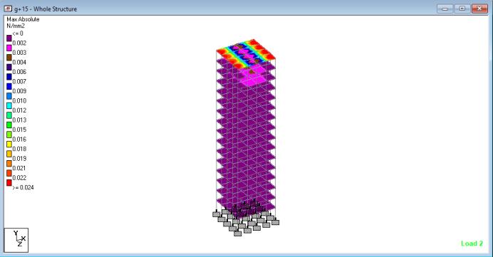
Theabsolutepressureplotonplatesduetothermalloading isshowninfigure14whichshowshigherabsolutepressure at the topmost plate wherein the magnitude is nearly .022N/mm2
When story changes from G+10 to G+15, the story drift increases by approximately 259.2%. This substantial increaseindicatesasignificantriseinlateraldeformationas the building height increases from G+10 to G+15. When numberofstorieschangesfromG+15toG+20,thestorydrift increasesbyapproximately33.0%.Therateofincreasein lateraldeformationisslowercomparedtotheincreasefrom
International Research Journal of Engineering and Technology (IRJET) e-ISSN: 2395-0056
Volume: 11 Issue: 08 | Aug 2024 www.irjet.net p-ISSN: 2395-0072
G+10toG+15butstillsignificant.Whennumberofstories G+10 to G+20, overall, the story drift increases by approximately 377.6%. This highlights the progressive increase in lateral deformation as the building height increasesfromG+10toG+20.Thesefindingsindicatethat lateral deformation becomes more pronounced as the buildingheightincreases.Thesignificantincreaseinstory drift, especially between G+10 and G+15, suggests that structural design considerations need to account for increasedlateralforcesandpotentialdeformationsathigher elevationstoensurestabilityandsafety.
[1] A. Ghali, R. Favre, M. Elbadry, Concrete Structures: Stresses and Deformations, Chapman and Hall, London, 1986.
[2] AASHTO, Interim Specifications for the Guide Specifications of Design and Construction of Segmental ConcreteBridges,firsted.,TheAmericanAssociationofState Highways and Transportation Officials, Washington, D.C., 1994.
[3]AASHTO,LRFDBridgeDesignSpecifications,fifthed.,The AmericanAssociationofStateHighwaysandTransportation Officials,Washington,D.C.,2005.
[4]M.Elbadry,A.Ghali,Temperaturevariationsinconcrete bridges,J.Struct.Eng.ASCE109(10)(1983)2355–2374.
[5]M.Elbadry,A.Ghali,Nonlineartemperaturedistribution and its effects on bridges, in: IABSE Proceedings, Zurich, 1983,pp.169–191.
[6]EssamH.EL-Tayeb,SalahE.EL-Metwally,HamedS.Aksar, AhmedMYousef“AnalysisofRCFlatslabsystemforthermal loads”InternationalJournalofEngineeringandInnovative Technology(IJEIT)Volume4,Issue12,July2015
[7] Zafar Mujawar, Prakarsh Sangave, January, 2015. “ComparativeEvaluationofReinforcedConcrete,Steeland CompositeStructureundertheEffectofStaticandDynamic Loading”. ISSN: 2248-9622, Volume 5, Issue 1, IJERA, Pg.no:41-44.
[8] Prakarsh Sangave, Nikhil Madur, Sagar Waghmare, RakeshShete,VinayakMankondi,VinayakGundla.February, 2015.“ComparativestudyofAnalysisandDesignofRCand steelstructure”.ISSN:2229-5518,Volume6,Issue2,IJSER
[9]Sattainathan.A,Nagarajan.N.March,2015“Comparative studyonthebehaviorofRCCsteelandcompositestructure (B+G+20 storeys)”. ISSN: 2395-3837, Volume 1, Issue 3, IJACEE,Pg.no:21-26.
[10]Zaveri,BhavinH.,BhargavK.Panchotiya,SmitU.Patel, andPratikA.Bilimoria.2016.“ParametricStudyofRCC,Steel
and Composite Structures under Seismic Loading.” InternationalJournalofCivilEngineeringandTechnology7 (4):127–47
[11] MOHD AMIR KHAN Comparative Study of R.C.C & StructuralSteel-ConcreteCompositeFrameforLinearand Non-LinearAnalysis
[12]GorakhVinit,NishitKadia,KiranmoySamanta,October2018. “Comparative study of RCC and steel structure for differentfloorheights”.ISSN:2349-2163,Volume5,Issue10, IJIRAE.
[13] Jyothi D N, February-2018 “Comparative Analysis of RCCandSteelstructure”.ISSN:23950072,Volume5,Issue2, IRJET.
[14] Paulo A. G. Piloto, Lucas M.S. Prates, Carlos Balsa, RonaldoRigobello‘FIRERESISTANCEOFCOMPOSITESLABS WITH STEEL DECK: EXPERIMENTAL ANALYSIS AND NUMERICALSIMULATION
[15] Pallavi Harish Wagh, Dr. S. K. Kulkarni, Vishwajeet Kadlag,2019.“ComparativeStudyonAnalysisandDesignof RCCandCompositeStructure”,ISSN:2454-132X,Volume5, Issue3,IJARIIT.