
International Research Journal of Engineering and Technology (IRJET) e-ISSN: 2395-0056
Volume: 11 Issue: 08 | Aug 2024 www.irjet.net p-ISSN: 2395-0072

International Research Journal of Engineering and Technology (IRJET) e-ISSN: 2395-0056
Volume: 11 Issue: 08 | Aug 2024 www.irjet.net p-ISSN: 2395-0072
Mr. Rushikesh Rajendra Hedgire1 , Mr. R. R. Badeghar 2
1P.G. Student, Department of Civil Engineering, N.B. Navale Sinhgad College of Engineering, Solapur 2Assistant Professor, Department of Civil Engineering, N.B. Navale Sinhgad College of Engineering, Solapur
Abstract - Accumulation of growing population especially in developing countries has resulted in an increasedheightofbuildings,thisneedcreatingimpacton structural development of tall building. And hence tall buildingconstructionhasbeenrapidlyincreasingworldwide. Thedevelopmentinconcretetechnologyoverthetwentieth centurycoveringmaterials,structuralsystems,analysisand constructiontechniques,madeitpossibletobuildconcretetall buildings. The primary function of a structure is achieved throughtheutilizationofvariousstructuralsystems.These systemsincludebracingsystems,moment-resistingframes, and shear walls. When aiming to control the horizontal displacement of a structure, it is crucial to prioritize the lateralforcesasthemostsignificantfactors.Overtheyears,a varietyofmechanismshavebeendevelopedtoresistlateral loads. The utilization of outrigger-belt truss systems is widespreadgloballyduetotheirexceptionalefficiency.The outrigger with belt truss is a structural solution that effectively regulates excessive deviation caused by lateral tension.Theimplementationofthissolutionwillleadtoan improvement in the performance of the building. It will effectivelyprotectthebuildingfrompotentialdamagecaused by both seismic and atmospheric stresses, including both structural and non-structural harm. The current study utilized the Etabs 2018 software to simulate a multi-story R.C.C. building consisting of 40, 45, and 50 floors. The researchonresponsespectrumisconductedspecificallyon structures that are situated in zone III. The Etabs 2018 software is designed to analyze building models and investigate the effects of various parameters. These parametersincludemaximaldisplacement,timeperiod,base shear,storeyshear,andbasemoments.
Key Words: Outrigger-belt truss system, tall building, Responsespectrumanalysis,Etabssoftware.
An outrigger system is a horizontal component that resemblesadeepbeam.Itisusedtoincreasetherigidityand strengthofastructureagainstoverturningbyconnectingthe building core or spine to the farthest or exteriormost columnsandmaintainingthecolumnsinplace.Thelateral movement is reduced by implementing this solution. The utilizationofcoreoutriggersystemsisacommonpracticein high-risestructureswithaslenderprofilewhentheprimary cause of the building's sideways movement is the overall
bending deformation, such as story drifts, and the force causingthebuildingtotipoverexceedstheforcecausingit toshear.Thesecoreoutriggersystemsserveasthelateral load resisting systems in such cases. The utilization of outriggersisimplementedtocreateatension-compression pairintheperimetercolumnsinsituationswherethecentral core of a structure endeavors to tilt. The aforementioned process facilitates the reversion of the core to its initial position and augments its ability to resist overturning by amplifyingitsrigidity.Theoutriggerbeamsorcrossbracing supports, which are attached to the external columns and shearwall,exhibitacertainlevelofcomplexity.However,it iswidelyacknowledgedthatthekeyfactorsthatimpactthe performanceoflinkedwallsystemsaretheproperrigidity andstrengthoftheoutriggerbeams.Inordertominimize lateraldeflectionandinter-storydrift,itiscrucialtouphold a high level of overall rigidity in tall structures. The performance of the outrigger system is affected by the outrigger locations along the height of the building, the numberoflevelofoutriggersprovided,theirplanlocations, presence of the belt trusses, outrigger truss depth and primarystructuralmaterialsusedinourstudy,bracedcore frame i.e. reinforced concrete shear wall core acting in conjunctionwiththeconcrete.belttrussandoutriggerstruts areprovidedwhichresisttheearthquakeloadsbystiffening thewholestructure.
Komal et. al. [1] Theprimaryfactorsthatcontributetothe susceptibility of a high-rise structure's performance are storeydisplacementandstoreydrift.Thesetwophenomena areprimarilycausedbyseismicforcesinregionswithhigh seismicactivity.Severalmethodologieshavebeenemployed to improve the efficiency of tall structures in various researchprojects.Theutilizationofcoreshearwalls,bracing systems, dampers, and other comparable measures are encompassedbythesemethods.Althoughthesemethodscan partially reduce storey displacement, the overall performance degradation of the building is ultimately limited by storey drift. The study project is utilizing the outrigger technique, which is considered outdated, to minimize the disturbance of the structure during seismic tremors.Thereasonforthisisthepresenceofaconstraint. The purpose of this investigation is to evaluate the performanceofthecantileverstructuralsysteminhigh-rise structureslocatedinseismiczones.Thisevaluationwillbe
International
Volume: 11 Issue: 08 | Aug 2024 www.irjet.net p-ISSN: 2395-0072
conductedbyanalyzingtheexistingliteratureonthesubject. Theperformanceofthestructureisgreatlyimpactedbythe specificplacementanddepthoftheoutriggers.Additionally, studieshaveshownthattheoutriggerstructuralsystemand coresystemhave theability toeffectivelydecreasestorey drifttoanacceptablelevel.However,itshouldbenotedthat these systems only provide partial mitigation of storey displacement.
Anju et. al. [2] Theoutriggersystemeffectivelyreducesthe seismicreactivityoftallcore-tubeconstructionsbyutilizing the axial rigidity of the perimeter columns. A dampedoutrigger system has been proposed for the purpose of reducing seismic energy. This system involves integrating dampersintotheoutriggermechanism.Theobjectiveofthis studyistoanalyzeandevaluatetheseismicperformanceofa damped-outrigger system that incorporates a bucklingrestrainedbrace(BRB-outrigger).Theseismicresponseof the structure is significantly mitigated through the utilization of the buckling-restrained brace (BRB) and the outrigger effect, which effectively dissipate energy. This studyproposesa methodologyfor evaluatingtheinelastic seismic response of structures equipped with multiple dampedoutriggersusingaspectralanalysis(SA)approach. Themaingoalsofthisstudyaretoidentifythemosteffective heightsforplacingoutriggersinastructurethatisequipped with BRB-outriggers. Additionally, the study aims to establishtherelationshipsbetweentheaxialstiffnessofthe BRB, the axial stiffness of the perimeter column, and the flexuralrigidityofthecorestructure.Thesecorrelationsare important for minimizing the seismic response of the structure. Analytical models are utilized to conduct nonlinear response history analysis and spectral acceleration(SA)forstructureswithheightsof64m,128m, 256m,and384m.Attheconclusionofthisinvestigation,a designrecommendationisprovidedforthepurposeofinitial design.Thisstudyaimedtoassesstheseismicbehaviorof structuresequippedwithmultiplebuckling-restrainedbrace (BRB) outrigger systems. The assessment was conducted usingasimplifiedmodelandsensitivityanalysisapproach. TheseismicresponseofthedualBRB-outriggersystemcan bereducedbyanalyzingtheoptimalrelationshipsbetween the axial stiffness of the two BRBs, axial stiffness of the perimeter columns, flexural rigidity of the core structure, andthemosteffectiveoutriggerheights.
Abeena et. al. [3] The structural efficiency of lofty structuresissignificantlyinfluencedbytheirlateralrigidity andresistancecapabilities.Outriggersystemsarecommonly usedasstructuralsystemsintallbuildings,especiallythose with consistently designed floors. The utilization of outriggers in construction was first observed in the early 1950s,whichcoincidedwiththedevelopmentoftheconcept ofdeepbeams.Astheheightofastructureincreases,deep beamsundergoatransformation,leadingtotheconstruction of either concrete walls or, more recently, steel truss outriggers that have a minimum height of one story. The
formandintendedfunctionofoutriggershavebeenmodified due to the increased variety of materials that can now be utilized in their construction. The analysis is closely connected to the design and construction challenges associatedwiththeoutriggers.Theprocessofcompression willinevitablyimpactthedimensionsofboththecentraland outer components. This article presents a comprehensive analysis of the outrigger system, a structural component usedintallbuildings.Itcoversthehistoricalevolutionofthis system and explores its various applications in different contexts. In this section, we will present and discuss the outrigger concept, which is considered the most efficient arrangement, as well as the factors that need to be consideredinitsdesignandconstruction.
Sreelekshmi et. al. [4] Theriseinthenumberofhigh-rise buildings in metropolitan areas can be attributed to the increasingdemandforaccommodation.Theprobabilityof oscillationintallstructuresisheightened bythetendency towardsslimmerconstructionswhentheyexperiencelateral forces.Shearwallsaresuitableforstructureswithaheight of 20 stories. However, to reduce the impact of these pressures, it is essential to incorporate additional lateral load resisting devices in taller structures. The outrigger systemiswidelyrecognizedasahighlyefficientandpopular systemduetoitsresilientlateralrigidity,cost-effectiveness, and straightforward construction. The outrigger braced structureisastructuraldesignknownforitshighefficiency inconnectingthecentralcoretotheoutsidecolumns.The constructionofthesesystemsisdesignedtopreventtilting bycreatingatension-compressionpairinthesurrounding columnswhenthecentralcorerotatesattheoutriggerlevel. Thedatacollectedinthisstudyallowustodrawconclusions about the overall behavior of outrigger braced structures when subjected to lateral loads. The response spectrum techniquewasutilizedtoconductananalysisonthechosen models.Thefocusoftheinvestigationwastocomparethe seismic performance of outrigger placements in a typical reinforcedconcretestructure,withaspecific emphasison theutilizationofabracedframecoreandashearcore.
Daril et. al. [5] Thepurposeofthisstudyistopresentanew design that utilizes energy-dissipation outriggers constructedwithbucklingrestrainedbraces(BRBs)instead ofconventionaldiagonalreinforcement.Theobjectiveofthis study is to improve the seismic performance of high-rise buildingstructuresthatareequippedwithoutriggers.Acase studywasconductedtoassesstheseismicperformanceof thenewlyconstructedstructure. Twotall structureswere planned for construction: one utilizing conventional outriggers, while the other incorporating outriggers specificallyengineeredforenergydissipation.Thefollowing articlepresentsasuccinctoverviewoftheoutriggersystem concept, encompassing its benefits and structural composition. The investigation provides a comprehensive analysis of different types of outriggers, including conventional, offset, and virtual. The purpose of this
International Research Journal of Engineering and Technology (IRJET) e-ISSN: 2395-0056
Volume: 11 Issue: 08 | Aug 2024 www.irjet.net p-ISSN: 2395-0072
document is to demonstrate the advantages of the virtual systemcomparedtoothersystems.Thestructuralsystem, whileconceptualinnature,hasthecapabilitytosatisfythe technicalandfinancialrequirementsofatallskyscraper.The researchstudy not onlycomparesthe virtual system with theclassicoutriggersystem,butalsooffersacomprehensive analysisofvariouslateralloadresistingsystems.
Roy et. al. [6] The objective of this study is to assess the feasibilityofutilizingahigh-riseoutriggerstructuralsystem for withstanding seismic activity in areas prone to earthquakes.Thiswillbeachievedbyconductingananalysis onatallbuilding.Thepurposeofthisarticleistoprovidea concise introduction to supplementary structural systems andofferacomprehensiveoverviewoftheOutriggerSystem. The optimal position for an outrigger in a grid frame, in order to sustain seismic stresses, is determined to be between 0.4-0.48 times the height of the structure. The heightismeasuredfromthebaseofthebuilding.Outriggers areinstalledatmid-heighttominimizestoreydisplacement. Theoptimalreductionindisplacementisattainedbysetting theheightratiosofthetwooutriggersto1.5andensuring thattherelativeaxialrigidityofamulti-outriggersystemis 0.75. The relationship between the displacements of the outriggersandtheirdepthisinverselyproportional.
Bishal et. al. [7] Theobjectiveofthisstudyistoproposea design strategy that effectively reduces the size of the primary structural components, including the core wall, outrigger,andexternalcolumns.Thisisachievedbyutilizing ageneticalgorithmtodeterminetheoptimalpositionsfor outriggers. The objective of this study is to develop an effectivemethodforregulatingthelateraldisplacementofa high-rise building. The optimal design of the primary structuralelements,includingthecorewall,outriggers,and outsidecolumns,inanoutriggersystem,isdeterminedby considering various design criteria. These criteria include theinstallationlocationoftheoutriggerandthesectionsof themainstructuralmembers.Thesolutionswereoptimized through the utilization of a genetic algorithm (GA) that aimed to minimize the total volume of the principal structuralelements.Theimplementationoftwoadditional constraintcriteriawascompleted.Thesecriteriaincludethe measurementofhorizontaldisplacementattheupperlevel andthedeterminationofthemaximumbendingtensionat thebaseofthecorewall.Thetotalcapacityofthebuilding's core wall, outrigger, and external columns is observed to decreaseasthenumberofstorieswithoutriggersincreases. Inaddition,theinstallationofadditionaloutriggersledtoan enlargementoftheexternalcolumnandareductioninthe dimensions of the core wall and outrigger. The observed outcomeisadirectconsequenceofthecorrelationbetween the rising count of outrigger installations and the correspondingincreaseinthemomentexertedontheouter columnsthatarelinkedtotheseoutriggers.Simultaneously, thereisadecreaseinthemomentresistedbythecorewall. Thereductioninquestionexhibitedthehighestmagnitude
when one to two outriggers were integrated, while it demonstrated the lowest magnitude when three to four outriggerswereintegrated.Thedeterminationoftheoptimal solutions for the outrigger system was based on the maximum displacement constraint, irrespective of the numberofstorieswheretheoutriggerswereinstalled.The volumeofthesystemwasminimizedbyimplementingthese solutions.However,itisimportanttonotethattheflexural bendingmomentatthebaseofthecorewalldecreasedwhen thenumberofverticallymountedoutriggersincreased.This isincontrasttothefactthatthemaximalbendingstresses increased due to the decrease in the core wall's second momentofinertia.
Kasi et. al. [8] The study aimed to determine the most effectivepositioningforsteeloutriggersystemsandassess thevulnerabilityofhigh-risesteelcompositestructuresto wind loading. An analysis is conducted to determine the optimallocationforthesteelbeltandoutriggersystems.The studyinvolvestestingdifferentconfigurationsofsingleand double level outriggers for composite structures with varyingsizes,forms,andheights.Afiniteelementanalysisis performedtoevaluatedifferentbuildingconfigurations,such as rectangular, octagonal, and L-shaped structures, each consisting of 28, 42, and 57 storeys. The 28-story model demonstratedsuperiorperformanceacrossallthreedesign configurations as a result of the inclusion of upper-level bracings.Tooptimizethereductioninlateraldeflection,it mayberequiredtoinstallanadditionalsetofoutriggersat the midpoint of structures with 42 stories. The 57-story model featuring a double belt-truss and outrigger levels shouldbeoutfittedwithasecondaryoutriggerpositionedat a height equivalent to two-thirds of the total height, as determinedfromgroundlevel.
Chetan et. al. [9] Ananalysiswasconductedbytheauthor onatallsteelstructureinordertoinvestigatetheimpactof adjustingthedepthoftheoutriggeronthebehaviorofthe system.Theresearchstudyfocusesonanalyzingbothstatic anddynamiceffectsresultingfromreducingthedepthofthe outrigger. In this analysis, a comparison is conducted betweenthestructuralsystemofoutriggersandthecentral coreatdifferentdepths.Theoutriggerdepthisreducedto two-thirdsandone-thirdofthestoryheight,inaccordance with the building's overall height. The belt-truss depth of each structure is uniform and matches the height of a standardstorey.Theoutriggerstructuralsystemisutilized toestablish a connection betweenthe buildingcoreand a remote column, resulting in an enhanced rigidity of the structure. When the outrigger depth is decreased to twothirdsofthestoryheightinsteadofthefullstoryheight,the lateral displacement and story drift are reduced by approximately4%to5%inthecaseofvariabledepth.Upon conducting a comparison between the outrigger's performancewhenoperatingatfullstoryheightandwhen operatingatareduceddepth,itwasobservedthatthereis nonoticeabledifferenceinperformance.
Volume: 11 Issue: 08 | Aug 2024 www.irjet.net p-ISSN: 2395-0072
Alok et. al. [10] Themainpurposeofthisarticleistoassess theeffectivenessofeachoutrigger,optimizetheplacement of outrigger sites, and examine the use of outriggers in a constructionprojectinvolvingthreeoutriggers.Ananalysis was conducted on nine three-dimensional models of the system, with each model representing a thirty-story structure.Thepurposeoftheanalysiswastoevaluatethe reductioninlateraldisplacementcausedbytheplacementof theoutriggerandbelttrusssystem,underwindandseismic loadingconditions.Thedisplacementofthe30-storymodel canbedecreasedbyupto23%bystrategicallyplacingthe firstoutriggeratthehighestpointandthesecondoutrigger at the structural height. The utilization of belt truss and outriggersystemsinhigh-risebuildingshasbeenshownto enhance structural efficiency and increase rigidity when exposedtolateralforces,asevidencedbythefindingsofthe aforementionedexperiment.Theeffectivenessofdeviation reduction is not significantly improved when using an outriggerasacaptrussontheuppermostlevel,ascompared toabelttruss.Basedontheavailableinformation,itcanbe deducedthattheoptimalrangeoftheoutriggerisequalto halftheheightofthestructure.
Theobjectiveofcurrentresearchistoevaluatethestructural behavior of RC framed building subjected to lateral loads. Thestructuralanddynamicanalysisofbuildingisconducted usingETABSsimulationsoftware.Theanalysisofbuildingis conductedwithandwithoutoutriggerstructuralsystem.
Theprimaryobjectiveofthisresearchistoinvestigatethe behaviorofG+40storyreinforcedconcreteframestructures thatpossessasquareorrectangulargeometryandaregular arrangement. The floor height is specified as 3.2 meters. Additionally, the frame structure's specific characteristics arespecified. The Etabssoftware is employed to generate modelsbystrategicallypositioningrigidoutriggerstructures atvariouslocationsonthebuildings.Diversecategoriesof burdens are assessed. Numerous variables influence the structure's static behavior. The live load is determined in accordancewithIS875PartIII,thedeadloadiscomputedin accordancewiththespecificationsofIS875PartI,andthe lateralloadisdeterminedinaccordancewiththeguidelines ofIS1893(part1)2016.Theresponsespectrumanalysisof three-dimensional reinforced concrete structures with a heightof40storeyswasperformedusingtheEtabsprogram. Theoutriggerbelttrusssystem'sefficacyinrelationtobase moments,baseshear,basedisplacement,timeperiod,and storeyshear,amongotheraspects,willbedemonstratedby theanalysis'sconclusions.
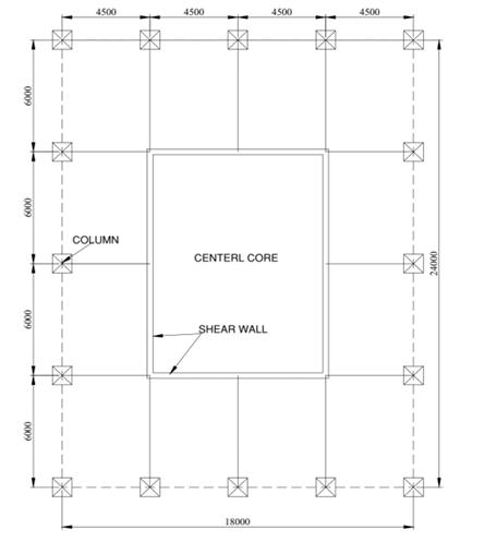
1: Planofrectangulargeometrywithoutoutrigger belttrusssystemforzoneIII
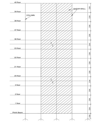
2: Elevationofrectangulargeometrywithout outriggerbelttrusssystemforzoneIII
International Research Journal of Engineering and Technology (IRJET) e-ISSN: 2395-0056
Volume: 11 Issue: 08 | Aug 2024 www.irjet.net p-ISSN: 2395-0072
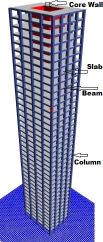
3: 3DViewofrectangulargeometrywithout outriggerbelttrusssystemforzoneIII
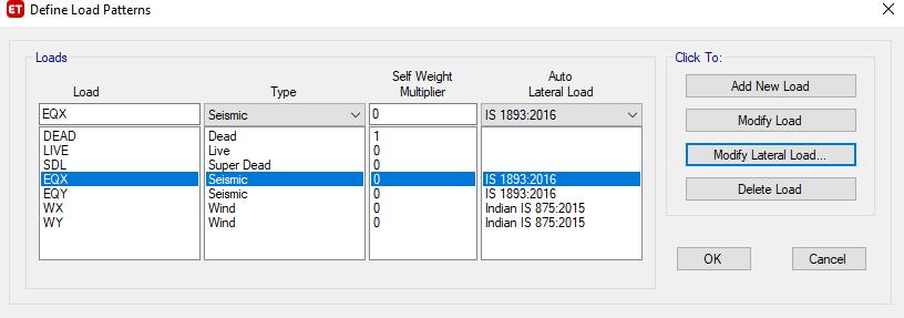
4: Loadpatterndefinition
Gravitypressuresrefertothedownwardforcesexerteddue to the acceleration caused by gravity. The internship program was primarily structured into three distinct
categories: The self-weight of structural elements is determinedbytheirdimensionsandcomposition.
Overlappeddeadloadsrefertotheloadsthatareproduced by permanent fixtures and fittings, such as ceilings, air conditioning ducts, floor treatments, and dividers. The expectedinertloadvaluetobeappliedtothismodelis1.5 kN/m2
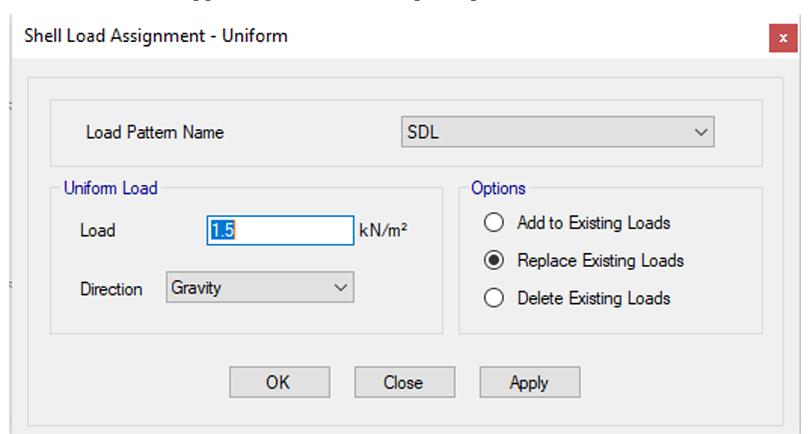
5: Superimposeddeadloads
LiveLoadIntensityspecified(Publicbuilding)=4kN/m2
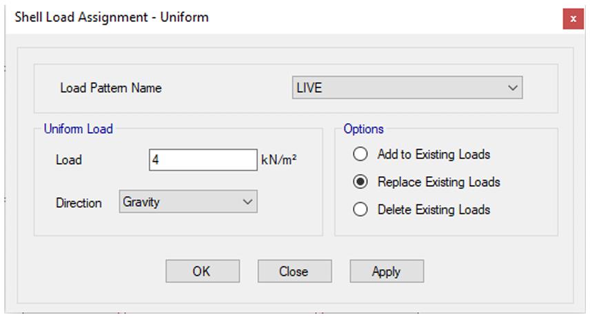
Figure 6: Liveloads
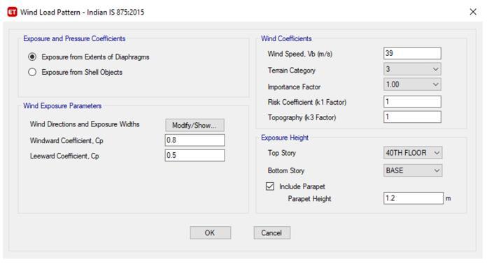
Figure 7: WindLoads
5. RESULTS AND DISCUSSION
Storey shear values for rectangular geometry with and withoutoutriggerbelttrusssystemforzoneIIImodelsare
International Research Journal of Engineering and Technology (IRJET) e-ISSN: 2395-0056
Volume: 11 Issue: 08 | Aug 2024 www.irjet.net p-ISSN: 2395-0072
obtainedusingResponsespectrumanalysisfromtheEtabs software.
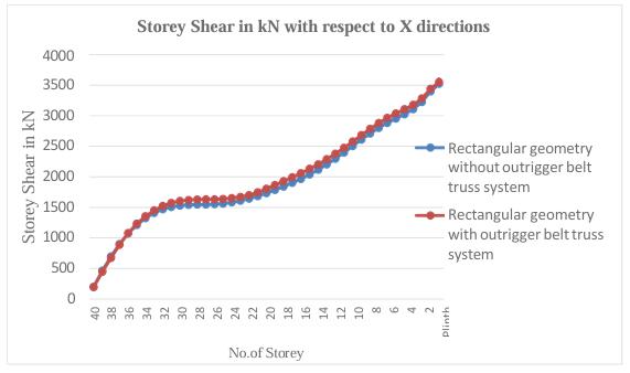
Figure 8:StoreyShearinkNwithrespecttoX
Storey shear values for rectangular geometry with and withoutoutriggerbelttrusssystemforzoneIIImodelsare obtainedusingResponsespectrumanalysisfromtheETABS software
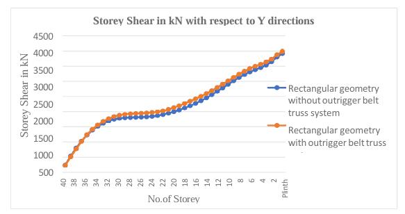
Figure 9:StoreyShearinkNwithrespecttoY
Baseshearvaluesforrectangulargeometrywithandwithout outriggerbelttrusssystemforzoneIIImodelsareobtained usingResponsespectrumanalysisfromtheEtabssoftware
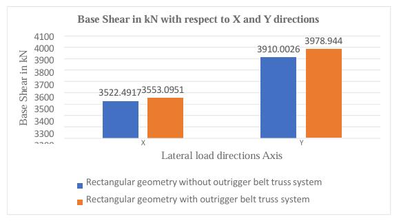
Figure 10:Baseshearwithrespecttoxandydirections
The base moment of Spec1 (Y) for rectangular geometry withoutriggerbelttrusssystemis4.58%morethanthatof rectangulargeometrywithoutoutriggerbelttrusssystem.2. The base moment of Spec2 (X) for rectangular geometry withoutriggerbelttrusssystemis4.53%morethanthatof rectangulargeometrywithoutoutriggerbelttrusssystem.
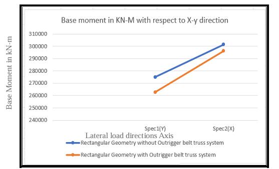
Figure 11: BasemomentinkN-mwithrespecttoXandYdirectionsfor50storey
Maximum Displacement values for rectangular geometry with and without outrigger belt truss system for zone III modelsareobtainedusingResponsespectrumanalysisfrom theETABSsoftwarezonesIIIforterracelevels.
International Research Journal of Engineering and Technology (IRJET) e-ISSN: 2395-0056
Volume: 11 Issue: 08 | Aug 2024 www.irjet.net p-ISSN: 2395-0072
Table1MaximumDisplacementsforrectangular geometrywithandwithoutoutriggerbelttrusssystemfor EarthquakeLoadCasefor40storey
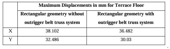
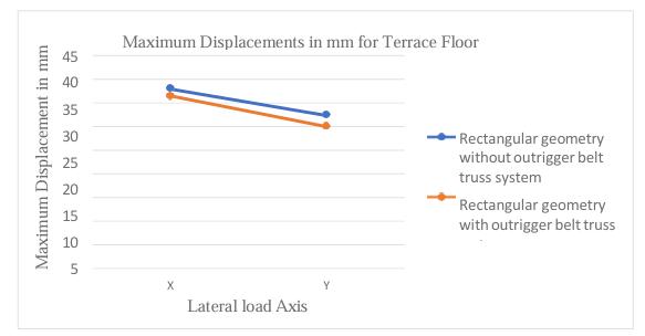
Figure12:MaximumDisplacementsforrectangular geometrywithandwithoutoutriggerbelttrusssystemfor EarthquakeLoadCasefor40storey
1. The X Axis of Maximum displacements for rectangular geometrywithoutoutriggerbelttrusssystemforzoneIIIis 4.25%morethanrectangulargeometrywithoutriggerbelt trusssystemforzoneIII
2. The Y Axis of Maximum displacements for rectangular geometrywithoutoutriggerbelttrusssystemforzoneIIIis 7.56%morethanrectangulargeometrywithoutriggerbelt trusssystemforzoneIII
Theperformanceandexecutionoftheoutriggerstructural system are significantly impacted by several factors, includingthelocation,cost,duration,type,andmaterialof bracing. The positioning of the outrigger beam has a substantial influence on the manner in which a building reacts to horizontal forces. In a typical single outrigger construction,itiscommonpracticetopositiontheoutrigger beamatthemidpointoftheheight.
1.Theutilizationofabelttrusssystem,perimetercolumns, outriggers,andcorestructuralwallsinabuildingresultsin improvedresistancetolateralforces,inaccordancewiththe specifications outlined in IS 1893-2016 (part 1). The outriggersserveto enhancethecoordinationbetweenthe perimetercolumnsandcorestructuralwalls,whilethebelt trussactsasaconduitfortheperimetercolumns.Theglobal lateralstiffnessisinfluencedbyseveralfactors,includingthe flexural stiffness of the outrigger components, the axial stiffnessoftheoutriggedcolumns,andtheflexuralstiffness
of the outrigger elements that connect the perimeter columnstothecorestructuralwalls.
2.Therecommendedpositioningforoutriggersinasystem withtwooutriggersisasfollows:thefirstoutriggershould bepositionedatadistanceof0.9Hfromthebottomofthe structure,whilethesecondoutriggershouldbepositionedat adistanceof0.5Hfromthebottom.
3.Theoutriggerstructuraltechniqueenhancesthestructural stiffness of the building by linking the building core to a remotecolumn.Thisconnectionenablestheentirestructure to act as a cohesive unit in withstanding lateral loads.
4.Theutilizationofanoutriggerstructuralsystemisknown foritsexceptionalefficacyinmitigatingtheadverseeffectsof windandseismicforces.Thisisachievedbyimpartingahigh degreeofrigiditytotheoverallstructure.
5. Earthquake load cases: The X-Axis of Maximum displacementsforrectangulargeometrywithoutoutrigger belt truss system for zone III is 4.25 % more than rectangular geometry with outriggerbelttrusssystem for zoneIII
6. Earthquake load cases: The Y Axis of Maximum displacementsforrectangulargeometrywithoutoutrigger belt truss system for zone III is 7.56 % more than rectangular geometry with outriggerbelttrusssystem for zoneIII.
7.Windloadcases:TheX-AxisofMaximumdisplacements forrectangulargeometrywithoutoutriggerbelttrusssystem forzoneIIIis9.23%morethanrectangulargeometrywith outriggerbelttrusssystemforzoneIII
[1]KomalJain.J,Mr.G.SenthilKumar“AnAnalyticalStudy on Outrigger Structure Using Non- Linear Dynamic Time History Analysis”. International Research Journal of Engineering and Technology, Volume: 03, Issue: 04, Apr2016.
[2]AnjuAkbar,SadicAzeez“EffectofOutriggerSystemin Multi Storied Irregular Building”. International Journal of ModernTrendsinEngineering&Research,Volume03,Issue 07,July–2016.
[3] Abeena Mol N M, Rose Mol K George “Performance of Different Outrigger Structural Systems”. International ResearchJournal ofEngineeringandTechnology,Volume: 03,Issue:09,Sep-2016.
[4]Sreelekshmi.S1,ShilpaSaraKurian“StudyofOutrigger Systems for High Rise Buildings”. International Journal of InnovativeResearchinScience,EngineeringandTechnology, Volume5,Issue8,August2016.
International Research Journal of Engineering and Technology (IRJET) e-ISSN: 2395-0056
Volume: 11 Issue: 08 | Aug 2024 www.irjet.net p-ISSN: 2395-0072
[5]DarilJohnPrasad,SrinidhilakshmishKumar“Comparison ofSeismicPerformanceofOutriggerandBeltTrussSystem inARCCBuildingwithVerticalIrregularity”.International JournalofResearchinEngineeringandTechnology,Volume: 05,Issue:20,Nov-2016.
[6] Roy Shyam Sundar, Gore. N. G “A Study on Tall RC Structure withOutriggerSystemSubjectedtoSeismicand Wind Loading”. International Journal of Engineering Research&Technology.Volume6,Issue02,February-2017.
[7]BishalSapkota,SurumiR.S,JeyashreeT.M“Comparative Study on Seismic Performance of High-Rise Building with Energy Dissipation and Outrigger Belt Truss System”. InternationalJournalofCivilEngineeringandTechnology, Volume8,Issue4,April2017.
[8] Prakarsh Sangave, Nikhil Madur, Sagar Waghmare, RakeshShete,VinayakMankondi,VinayakGundla.February, 2015.“ComparativestudyofAnalysisandDesignofRCand steelstructure”.ISSN:2229-5518,Volume6,Issue2,IJSER
[9]Sattainathan.A,Nagarajan.N.March,2015“Comparative studyonthebehaviorofRCCsteelandcompositestructure (B+G+20 storeys)”. ISSN: 2395-3837, Volume 1, Issue 3, IJACEE,Pg.no:21-26.
[10]Zaveri,BhavinH.,BhargavK.Panchotiya,SmitU.Patel, andPratikA.Bilimoria.2016.“ParametricStudyofRCC,Steel and Composite Structures under Seismic Loading.” InternationalJournalofCivilEngineeringandTechnology7 (4):127–47
[8]KasiVenkatesh,B.Ajitha “Behaviour ofa Buildingwith Outrigger Structure”. National Institute of Technical TeachersTraining&Research.May2017.
[9] Chetan Patel Y G, Kiran Kuldeep K N “The Study on Behaviour of Outriggers for Tall Buildings Subjected to LateralLoad”.Internationalresearchjournalofengineering andtechnology,Volume04,Issue07,July2017.
[10] Alok Rathore, Dr. Savita Maru “A Performance Based AnalysisofOutriggerStructuralSystemforVerticalIrregular TallBuilding”.Internationaljournaloftrendsinengineering andresearch,Volume4,Issue12,December2017.
[11]PremalathaJ,MrinaliniM“SeismicBehaviourofaMultiStoreyed Reinforced Concrete Irregular Building with Outrigger Belt Truss System”. International Journal of EngineeringandAdvancedTechnology,Volume-8,Issue-2S, December2018.
[12]IqraBanoAyazAhmadKhan,Prof.N.G.Gore“Effectof Outrigger Structural System on High-Rise Structures, SubjectedtoLateralLoads”IOSRJournalofMechanicaland CivilEngineering,Volume15,Issue6,Nov.-Dec.2018.