
International Research Journal of Engineering and Technology (IRJET) e-ISSN:2395-0056
Volume: 11 Issue: 08 | Aug 2024 www.irjet.net p-ISSN:2395-0072

International Research Journal of Engineering and Technology (IRJET) e-ISSN:2395-0056
Volume: 11 Issue: 08 | Aug 2024 www.irjet.net p-ISSN:2395-0072
Balraju Akhila1 and Dr. K. Naga Sujatha2
1M. Tech. Student, Dept. of Electrical and Electronics Engineering, JNTUHUCESTH, Hyderabad, India. 2Professor of Electrical and Electronics Engineering, JNTUHUCESTH, Hyderabad, India.
Abstract -The solar photovoltaic MPPT battery charge controllerforleadacidandnickel-cadmiumbatteriesusedin standalonesystemswerepresentedinthispaper.TheMPPT battery charge controller is implemented using a buck converter.Thepurposeofthecontrolleristoextendbattery lifeandboostphotovoltaic(PV)systemefficiency.Toachieve this, the three-stage charging strategy and the MPPT (Maximum power point Tracking) methodology were employed. The results shows that the lead acid battery controllersperformancegiveshighefficiencythanthatofthe nickel-cadmium battery controller performance. The proposed techniques were implemented in the MATLAB/SIMULINKenvironment.
Key Words: PV System, Perturb and Observe algorithm, Buck converter, Battery Charge Controller, Three-stage charging method.
Inthelasttenyears,solarphotovoltaicenergyhasdrawna lotofinterest.Upto181GWinstalledworldwide,itisoneof therenewableenergysourceswiththequickestgrowth[1]. The PV module's power-voltage characteristics vary depending on the surrounding air conditions and have a distinct peak. Taking into account the PV system's initial cost, it is always necessary to run photovoltaic cells at maximumpowerpoint(MPP).Dc-dcconverterinterfaceis necessary for this purpose between battery and SPV. Additionally,toextendthe battery'slife,thecontroller for chargingbatteriesisnecessary[2].PVcellproperties(I-Vor V-P) are also nonlinear and vary with temperature and insolation.ThemostexpensivepartsofstandalonesolarPV systemsarethe batteriesandPVmodules.Thelifespan of thebatteriesisshortenedwhentheyareconnecteddirectly to the PV modules since there is no safeguard against overcharging[3].Chargecontrollerscanbeusedtoprevent batteries from being overcharged, however they are less efficient than typical charge controllers since they do not operatePVmodulesatMPP.RunningthePVmoduleatits maximalpowerpointwillmaximizepowerdeliverytothe batteriesandenhanceefficiency[4].Additionally,alonger battery life requires the battery charging controller. Rechargeablebatteriesareoftenusedbyfreestandingsolar systemsasameansofenergystorage[5].Optimizingpower
distributiontothebatteriesandimprovingefficiencycanbe achievedbyoperatingthePVmoduleatitsmaximumpower point [6,7]. To charge the batteries a three-stage charging method is used which prevents the batteries from overchargingordeepdischarging.Thisworkalsopresentsa battery charge controller, whichisintended to extend the batterylife.WithMATLAB-SIMULINK,theentiresystemis simulated,andtheoutcomesareshown.
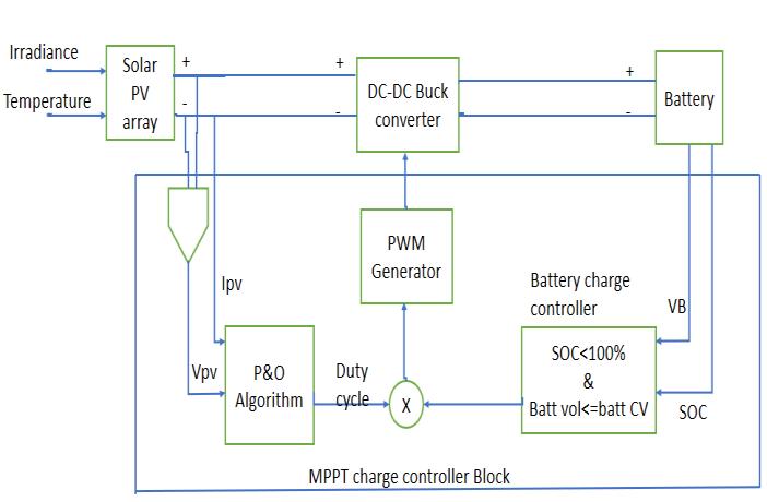
The above figure 1. Shows the block diagram of Solar PV MPPT battery charge controller. The solar irradiance and temperature are the input to the Solar PV array. The P&O technique takes the PV array current and voltage as the inputsandgivesthedutycycleasoutput.Thebatterycharge controllertakesthebatteryvoltageandinitialstateofcharge astheinputsandfollowsthethree-stagechargingmethod conditions and produces the current, voltage and state of chargeofbattery.Thedutycycleandoutputsfrombattery chargecontrollerarepassedthroughmultiplyblocktothe PWM generator for the output of the buck converter switchingdevice.
2.Maximum Power Point Tracking Battery charge controller
The MPPT battery charge controller block consists of Perturb and Observe technique and Battery charge controller.
International Research Journal of Engineering and Technology (IRJET) e-ISSN:2395-0056
Volume: 11 Issue: 08 | Aug 2024 www.irjet.net p-ISSN:2395-0072
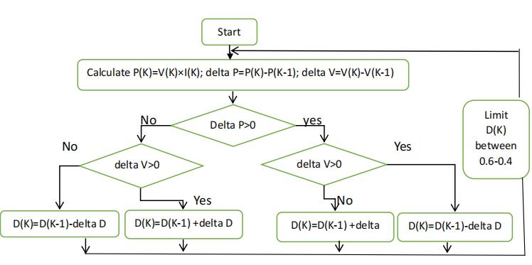
PerturbandObservetechniqueisthemostcommonlyused MPPT technique because of its easy implementation. This MPPT technique is used to improve the efficiency of solar panel. This algorithm alters the duty cycle of converter which changes the operating voltage of the PV Panel and observes the change in power output from PV Panel in response to perturbation. If the power increases the perturbation in same direction is continued, if the power decreases the perturbation direction is reversed. By ensuring adjustment of duty cycle based on the observed output, the P&O MPPT algorithm ensures that PV system operatesatitsmaximumefficiencyundersolarirradiance andcelltemperature.TheFlowchartofPerturbandObserve techniqueisshowninfigure2.
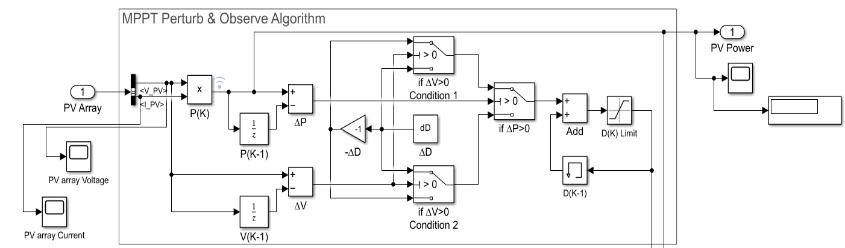
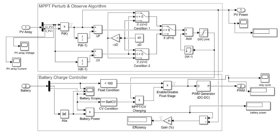
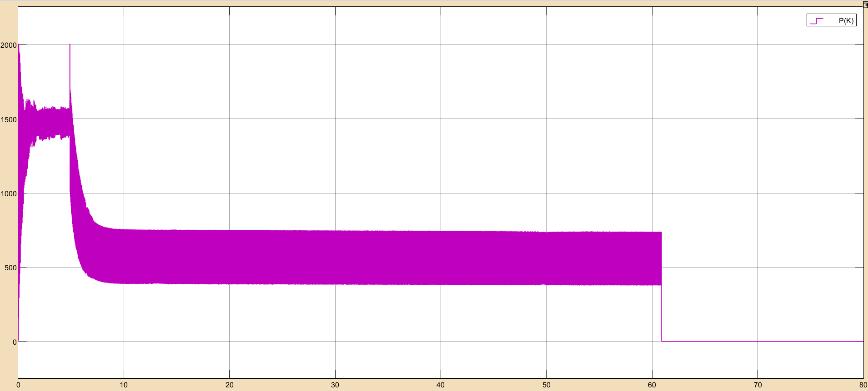
InFig.3,thePVarray'svoltageandcurrentareinputintothe Perturb and Observe MPPT Simulation model. By using a multiplyblockandP(K),thecurrent powerisdetermined. Theswitchblockusesthethree-if-elsecriteria.Settingthe dutycycle'sperturbationstepsizeispossiblewiththedelta Dblock.Basedonthethree-if-elseconditions,thedutycycle increase and decrement are determined. Next comes the adder with memory block D(K-1) and the duty cycle incrementanddecrementfunction.Batterychargecontroller blockiscoupledtodutycycle.
2.2.
Abatterychargecontrollermaintainstheparametersatthe batterywithinthelimitssetoutbythebatterymanufacturer
bymanagingthecurrentflowbetweenthePVarray,battery, and load. Three stages of charging are used to charge the batteryutilizingthebatterychargecontroller.Bulkcharging, absorptioncharging,andfloatchargingarethethreephases of the battery charge controller's three-stage charging technique.Bulkchargingraisesthebattery'svoltagebecause the battery charge controller draws the highest current possible from the PV array. The battery charge controller graduallylowersthebattery'scurrentwhilemaintaininga steady charging voltage during absorption charging. The batteryobtains100%stateofchargeduringfloatcharging. The flowchart of three stage charging method of battery chargecontrollerisshowninfigure4.
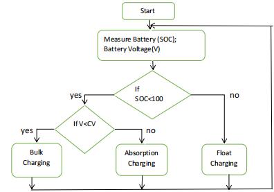
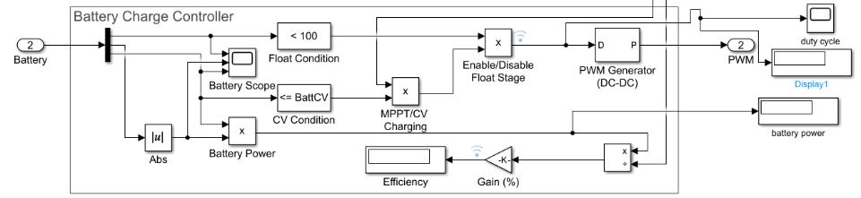
The Simulation model of battery charge controller is presentedinfigure5.Thebatterychargecontrollertakesthe stateofchargeandvoltagefromthebattery.Ifthecondition state of charge of battery less than 100% is true, it will disable the float stage and the duty cycle is allowed and passesthroughthemultiplyblocksothatthebatterycharge controller enters either in Bulk charging or Absorption charging. If the condition is false, so the battery state of charge is at 100% and enable the float charging without allowingthedutycycle.Toknowwhetherthechargerenters in either Bulk charging or Absorption charging, there is a condition i.e. battery voltage less than battery constant voltage.Ifthisconditionistrue,thenenableBulkcharging and allow the duty cycle and pass through MPPT/CV chargingmultiplyblockanddisablethefloatstagemultiply block, then through the PWM generator block to the buck converter output. If this condition is false, then enable Absorptionchargingandallowingthedutycycleswitching between MPPT and zero, and pass through the MPPT/CV charging multiply block and disable float stage multiply block, then through the PWM generator for the output of buckconverter.
International Research Journal of Engineering and Technology (IRJET) e-ISSN:2395-0056
Volume: 11 Issue: 08 | Aug 2024 www.irjet.net p-ISSN:2395-0072
3.DC/DC Converter
A buck converter is used for the implementation of MPPT battery charge controller. The buck converter steps down theinputPVarrayandmaintainsthepowerflowtocharge thebattery.ThebuckconverterconsistsofMOSFETdevice, inductor,diode,aninputandoutputcapacitor.DiodeD1is usedinordertopreventtheflowofpowerbackfrombattery toPVarray.Table1.Showsthespecificationswhichareused forbuckconvertertopology.
Table -1: Buckconverterparameters
InputVoltageofPVarray 146.4V
InputcapacitanceC1 0.001F
OutputcapacitanceC2 0.001F
InductanceL 0.01H
MOSFETRon 0.02ohms
DiodeforwardVoltageD2 0.5V
PWMswitchingFrequency fSW
Table -2: Solarpanelspecificationsat1000W/m2andcell temperature25oC
PARAMETERS
Twomodulesareconsideredinparallelwithfourmodulesin series for the given specific PV array with the following specificationsasmentionedintable2.
4.Simulation Model
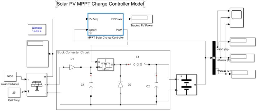
The Simulation model of Solar PV MPPT battery charge controllerisshowninfigure6.ItconsistsofSolarPVarray, DC-DC buck converter, battery and MPPT battery charge controller.TheMPPTbatterychargecontrollerconsists of Perturb &Observe MPPT algorithm and battery charge controller.Figure7ShowsthesubsystemofMPPTbattery chargecontrollermodel.ThePWMgeneratorisconnectedto theMPPTbatterychargecontrolleroutputinordertoturn onthebuckconverter'sswitchingmechanism.
5. Simulation Results
5.1 MPPT battery charge controller performance with lead acid battery
The battery block is set to a lead acid battery,24V,100AH capacity and initial state of charge 99.7% and simulation duration of 60sec, battery charging constant voltage of 28.8V.ThePVarraysolarirradianceissetto1000w/m2and temperature is set to 25oC.The performance of the MPPT
International Research Journal of Engineering and Technology (IRJET) e-ISSN:2395-0056
Volume: 11 Issue: 08 | Aug 2024 www.irjet.net p-ISSN:2395-0072
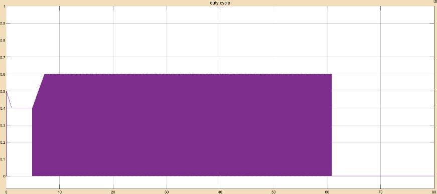
batterychargecontrollerwithleadacidbatteryisshownin figure8.
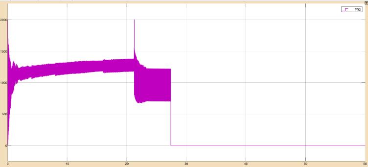
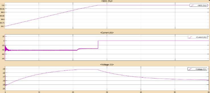
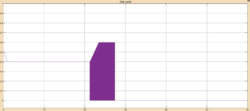
Accordingtotheresults,whenthebatteryvoltageandstate of charge are less than 100% and 28.8V, respectively, the batterychargecontrollerstartschargingthebatteryatMPPT bulkcharging.Thebatteryvoltageremainsconstantat28.8V for22secafteritenterstheabsorptionstage.Thedutycycle isswitchedbetweenMPPTandzeroduringtheabsorption stageinordertomaintainasteadychargingvoltageof28.8V, which is visible from 22 to 28 secs. The battery charge controllerswitchestothefloatstage,whichhasazeroduty cycle and a floating voltage of 26.19V, when the state of chargereaches100%in28sec.Theoverallefficiencyofthe Solar PV MPPT battery charge controller with lead acid batteryobtainedis18.04%.
5.2 MPPT battery charge controller performance with Nickel cadmium battery
The battery block is set to a Nickel cadmium battery,28.8V,100AH capacity and initial state of charge 99.7%, simulation duration of 80sec and battery charging constantvoltageof33.6V.TheperformanceofMPPTbattery
chargecontrollerwithNickelcadmiumbatteryisshownin figure 9.
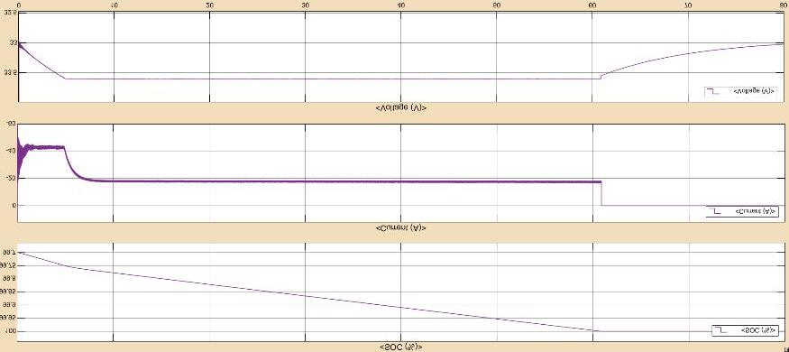
Accordingtotheprecedingplots,whenthebatteryvoltage andstateofchargearelessthan33.6Vandlessthan100%, thebatterychargecontrollerstartschargingthebatteryat MPPT bulk charging.The battery voltage remains steady steady at 33.6V for 4.7sec after it enters the absorption stage.The duty cycle is switched between MPPT and zero during the absorption stage in order to maintain a steady charging voltage of 33.6V, which is visible from 4.7 sec to 60.8sec.Thebatterychargecontrollerswitchestothefloat stage,whichhasazero-dutycycleandafloatingvoltageof 33.02V,whenthestateofchargereaches100%in60.8sec.
TheoverallefficiencyofthesolarPVMPPTbatterycharge controllerwithNickelcadmiumbatteryobtainedis22.74%.
International Research Journal of Engineering and Technology (IRJET) e-ISSN:2395-0056
Volume: 11 Issue: 08 | Aug 2024 www.irjet.net p-ISSN:2395-0072
Table 3:Parameter variation of Lead acid battery and Nickel cadmium battery
6. Conclusion
Withtheuseofa2000WPVarraysource,theMPPTbattery chargecontrollercantrackthemaximumpowerandusea three-stagechargingmechanismtochargea24Vleadacid battery.Similartothat,thismodelcancontrolthecharging of a 28.8V nickel-cadmium battery by monitoring the maximum power from a 2000W photovoltaic array and applyingathree-stagechargingprocess.TheMPPappearsat 0.0078secondsforleadacidbatteriesandat0.0056seconds for nickel cadmium batteries, according to a comparative analysisoftheMPPTbatterychargecontrollerperformance forleadacidandnickelcadmiumbatteries.Thismeansthat thecontrollercanreachtheMPPusingP&Otechniquefaster forthenickel cadmium batterythantheleadacidbattery. Hence, Choosing the Nickel cadmium battery which gives higherefficiencythantheleadacidbatterycanbebeneficial forstandalonesystemoperations,asitcanleadtoimproved reliability.
[1] Chiang,S.J.Shieh,H.J.Chen,M.C.“ModelingandControl of PV Charger System with SEPIC Converter”. Industrial Electronics,IEEETransactions,Vol.56,no.11,Nov2009.
[2] F.Liu,S.Duan,F.Liu,B.Liu,andY.Kang,“Avariablestep size INC MPPT method for PV systems,” IEEE Trans.Ind.Electron.,vol.55,no.7,pp.2622–2628,Jul.2008.
[3] H.DeBattistaandR.J.Mantz,”Variablestructurecontrol of a photovoltaic energy Converter,” IEE proce-Control TheoryAppl..,Vol.149,No.4,July2002.
[4]E.KoutroulisandK.Kalaitzakis,“Novelbatterycharging regulationsystemforphotovoltaicapplications,”Proc.Inst. Elect.Eng. Elect.PowerAppl.,vol.151,no.2,pp.191–197, Mar.2004.
[5]Salman,S.,AI, X.& WU, Z.Design ofa P-&-Oalgorithm based MPPT charge controller for a stand-alone 200W PV system. Prot Control Mod Power Syst 3, 25 (2018). https://doi.org/10.1186/s41601-018-0099-8
[6] Sivakumar, P., Kader, A. A., Kaliavaradhan, Y., & Arutchelvi, M. (2015). Analysis and enhancement of PV efficiency with incremental conductance MPPT technique under non-linear loading conditions. Renew Energy, 81, 543–550.
[7] Ishaque,K.,&Salam,Z.(2013).Areviewofmaximum powerpointtrackingtechniquesofPVsystemforuniform insolationandpartialshadingcondition.RenewSustEnerg Rev,19,475–488.
[8] Bendib,B.,Belmili,H.,&Krim,F.(2015).Asurveyofthe most used MPPT methods: Conventional and advanced algorithms applied for photovoltaic systems. Renew Sust EnergRev,45,637–648.
[9] Ramli, M. Z., & Salam, Z. (2014). A simple energy recovery scheme to harvest the energy from shaded photovoltaic modules during partial shading. IEEE Trans PowerElectron,29(12),6458–6471.
[10] DeBrito,M.A.G.,Galotto,L.,Sampaio,L.P.,eMelo,G.D. A., & Canesin, C. A. (2013). Evaluation of the main MPPT techniques for photovoltaic applications. IEEE Trans Ind Electron,60(3),1156–1167.
[11] Bennett, T., Zilouchian, A., & Messenger, R. (2012). Photovoltaicmodelandconvertertopologyconsiderations forMPPTpurposes.SolEnergy,86(7),2029–2040.
[12]Femia,N.,Petrone,G.,Spagnuolo,G.,&Vitelli,M.(2009). A technique for improving P&O MPPT performances of double-stage grid-connected photovoltaic systems. IEEE TransIndElectron,56(11),4473–4482.
[13]Suwannatrai,P.,Liutanakul,P.,&Wipasuramonton,P. (2011). Maximum power point tracking by incremental conductance method for photovoltaic systems with phase shifted full-bridge dc-dc converter. In Electrical Engineering/Electronics, Computer, Telecommunications and Information Technology (ECTI-CON), 2011 8th InternationalConferenceon(pp.637-640).IEEE.
[14] Chekired, F., Larbes, C., Rekioua, D., & Haddad, F. (2011). Implementation of a MPPT fuzzy controller for photovoltaic systems on FPGA circuit. Energy Procedia, 6, 541–549.
[15] Noguchi,T.,Togashi,S.,&Nakamoto,R.(2002).Shortcurrentpulse-basedmaximum-power-pointtrackingmethod formultiplephotovoltaic-andconvertermodulesystem.IEEE TransIndElectron,49(1),217–223.
[16] Tan, Rodney HG, Chee Kang Er, and Sunil G. Solanki. "Modeling of photovoltaic MPPT lead acid battery charge controllerforstandalonesystemapplications." E3s Web of conferences.Vol.182.EDPSciences,2020.
International Research Journal of Engineering and Technology (IRJET) e-ISSN:2395-0056
Volume: 11 Issue: 08 | Aug 2024 www.irjet.net p-ISSN:2395-0072
[17] Mohamed A. Eltawil, Zhengming Zhao, MPPT Techniques for Photovoltaic Applications, Renewable and SustainableEnergyReviews, 25,793-813(2013).
[18] B. Sree Manju, R. Ramaprabha and B. L. Mathur, "Modelling and control of standalone solar photovoltaic charging system," 2011 International Conference on Emerging Trends in Electrical and Computer Technology, Nagercoil, India, 2011, pp. 78-81, doi: 10.1109/ICETECT.2011.5760095.
[19]P.Shaw,P.K.Sahu,S. MaityandP.Kumar,"Modeling andcontrolofabatteryconnectedstandalonephotovoltaic system," 2016 IEEE 1st International Conference on Power Electronics, Intelligent Control and Energy Systems (ICPEICES), Delhi, India, 2016, pp. 1-6, doi: 10.1109/ICPEICES.2016.7853123.
[20] AnkurBhattacharjee,DesignandComparativeStudyof Three Photovoltaic Battery Charge Control Algorithms in MATLAB/Simulink Environment, International Journal of AdvancedComputerResearch,2,129-135(2012).
[21] IllanGlasner,JosephAppelbaum,AdvantageofBoostvs Buck Topology for Maximum Power Point Tracker in PhotovoltaicSystems, IEEEProceedingsof19thConventionof Electrical andElectronics Engineers inIsrael,(1996)
[22] Nicola Famia, Giovanni Petrone, Giovanni Spagnuolo, andMassimoVitelli“OptimizationofPerturbandObserve Maximum Power Point Tracking Method,” IEEE Trans., PowerElectron.vol...20,No.4,July2005.
[23] Z. Jiang and R. A. Dougal, “Multiobjective MPPT/chargingcontrollerforstandalonePVpowersystems underdifferentinsolationandloadconditions,”inConf.Rec. IEEEIASAnnu.Meeting,2004,pp.1154–1160.
[24]Patel,H.,&Agarwal,V.(2008).Maximumpowerpoint tracking scheme for PV systems operating under partially shaded conditions. IEEE Trans Ind Electron, 55(4), 1689–1698.
[25] Trishan Esram, Patrick L. Chapman, Comparison of Photovoltaic Array Maximum Power Point Tracking Techniques, IEEE Transactions on Energy Conversion, 22, 439-449(2007).