
International Research Journal of Engineering and Technology (IRJET) e-ISSN: 2395-0056
Volume: 11 Issue: 08 | Aug 2024 www.irjet.net p-ISSN: 2395-0072

International Research Journal of Engineering and Technology (IRJET) e-ISSN: 2395-0056
Volume: 11 Issue: 08 | Aug 2024 www.irjet.net p-ISSN: 2395-0072
Hariom Narware1 , Dr. E Vijay Kumar 2
Department of Electrical Engineering, RKDF IST, SRK University,Bhopal. M.P, India
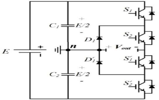
Abstract: Thecontinuoussupplyofcleanelectricalpowerhas become essential to modern civilization. However, the grid andtransmissionnetworkmaynotalwaysdelivercleanand reliable power. Understanding the variety of power quality problemsinthereceivedsupplyand thenatureoftheloadsis thefirstapproachtothepowerqualitysolution.Inthispaper performanceofthediodeclampedthree-levelinverter(DCTLI)usingsimulationandhardwareisevaluated.Performance evaluated for power quality of three-level diode clamped SPWMVoltagesourceinverter.FFT(FastFourierTransform) graph for DC-TLI and line current THD (Total Harmonic Distortion) values is compared with two-level inverter line voltageandcurrent.MLIs(multilevelinverters)areutilizedto increasethenumberofstepstoproducehighqualityoutput waveforms. MLIs are used to eliminate harmonics and increasetheinverter'sperformance.
Keywords: Power Quality, Solar PV Grid, Diode Clamped Three-LevelInverter,Photovoltaic,Grid-connected,renewable energy.
Thegridpowerqualityisaffectedbytherisingpenetrationof grid- connected renewable energy sources. Major power qualitychallengesincludeharmonics,frequencyvariation,and voltage fluctuation. Multi- level inverters are extensively employed in grid-tied PV systems because of their characterizedbylowercostandhigherefficiency.Owingtothe extensive use of nonlinear power electronics loads, ac distribution networks have suffered significant harmonic pollution.Nonlinearloadslikelampballasts,motorsdrives, electricweldingequipment,arcfurnaces,electronicsbattery chargers, etc. Harmonic standards and guidelines, such as IEEE-519-1992andIEC61000,governbestpracticesinpower system andnonlinear equipment design[1].Manystrategies canbeusedtoimprovethepowerqualityofinverters. This research develops a system that incorporates a three-level neutral point clamped (3L-NPC) inverter with a control strategythatkeepsthenecessaryvoltagesfortheinputDCbus voltage of a grid-tied three-phase PV system [3]. The multilevelinverter(MLI)forsolarinvertersystemsimproves through increased rating and improving performance and efficiency. The rating of MLI is increased by adding more voltage levels without increasing individual device ratings, andtheoutputvoltage'sharmonicsaredecreased.Thethree topologies of MLIs are: (1) Cascade H-bridge Multilevel
Inverter (CHBMLI),(2) Flying Capacitor Multilevel Inverter (FCMLI),and(3)DiodeClampedMultilevelInverter(DCMLI) [2]. For power quality enhancement, the researchers have consistentlyused,modified,tested,andimplementedvarious MLI configurations for a wide range of applications for medium/highpowerandmedium/highvoltagesystems[3][4]. Harmonicsmustberestrictedtoaspecificlevel,accordingto theIEEEstandard;otherwise,thecoreofpowertransformer may be saturated. Harmonics might be restricted in this scenariointwoways:ontheload sideorthesourceside.A powerconditioneriscommonly connectedacrosstheloadat thepointofcommoncoupling(PCC).Precisioninverterand controllerdesigngivescontroloverharmonicsatsourceside [5][6].AgeneralSVPWMalgorithmisproposedforthree-level inverter[5][7].Invertercontrolandoutputvoltagewithlosses aredescribed[8].Solarfedmultilevelinverterpowerquality improvement is discussed [9]. Reactive
Beforeyoubegintoformatyourpaper,firstwriteandsave thecontentasaseparatetextfile.Keepyourtextandgraphic files separate until after the text has been formatted and styled.Donotusehardtabs,andlimituseofhardreturnsto onlyonereturnattheendofaparagraph.Donotaddanykind of pagination anywhere in the paper. Do not number text heads-thetemplatewilldothatforyou.
Finally,completecontentandorganizationaleditingbefore formatting. Please take note of the following items when proofreadingspellingandgrammar:
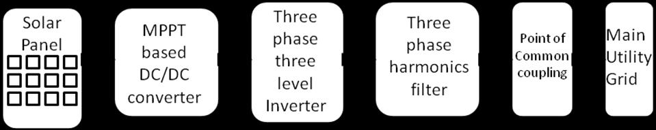
The proposed solar PV grid integration block diagram is exposedinFigure
1.Thesystemblocksrepresent(1)Solarpanel(2)MPPTDCto DCboostconverter(3)NPCthree-levelthreephaseinverter
Volume: 11 Issue: 08 | Aug 2024 www.irjet.net p-ISSN: 2395-0072
(4)threephaseharmonicsfilter(5)mainutilitygrid.Among thethreetopologiesofMLIs,DCMLIisintroduced.Theoutput powerisintegratedwithgridaftertheharmonicsfilterisused. TheDCtoACconverterusetoconvertDCintoAC.TheMPPT controlstrategyisappliedtotheboostconverter.TheDClink voltage is controlled using constant voltage control mode. AfterapplyingtheDQtransformationtoDCtoACconverter, the decoupling control structure calculates the three phase voltagetogeneratecorrectacwithoutharmonics.TheDC-TLI outputissynchronisedwiththemaingridusingphaselocked loop(PLL)[3].Ittransferstherequiredamountofpowerto thegridaspertheloadrequisite.Theswitchingoperationof theinverterisdeterminedbytheSPWMcontrol[11].
Sample paragraph, The entire document should be in cambriafont.Type3fontsmustnotbeused. Otherfonttypes may be used if needed for special purposes. The entire documentshouldbeincambriafont.Type3fontsmustnotbe used. Other font types may be used if needed for special purposes.
Thispaper presentsa modellingandsimulationwork of grid connected three-level diode clamped SPWM inverter. MPPT controller used in PV grid system to get optimum output.TheDClinkvoltageisconnectedwiththeDC-TLIand theoutputoftheinverterissynchronizedwiththemaingrid. Theinvertermaintainsthevoltageandfrequencyequaltothe gridvoltageandfrequency[11][12].SIMULINKblocksetsin MATLABareusedforthesimulationstudy.
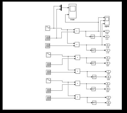
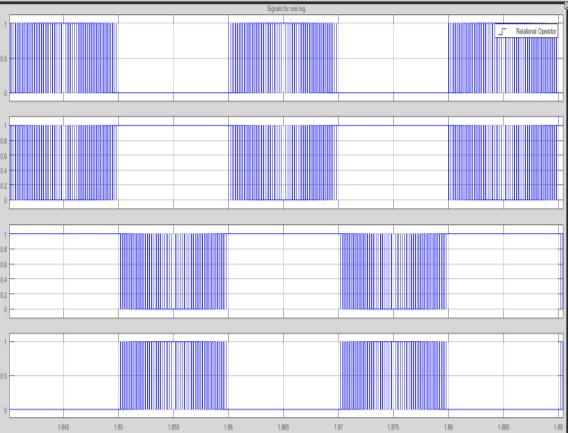
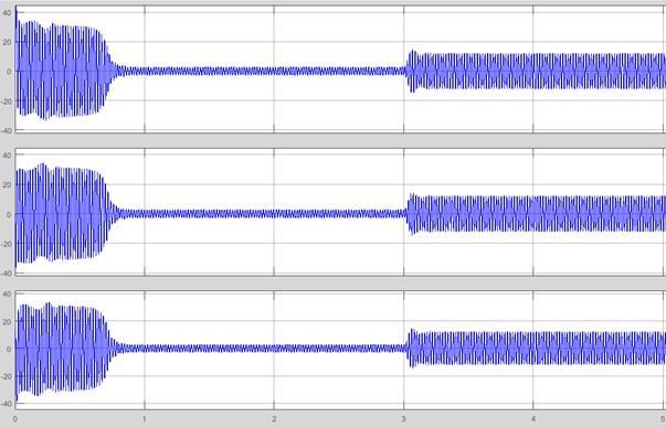
The effectiveness of the suggested topology and control algorithmistestedandpresentedusingsimulationresults.The simulationis donefortheinputvalueofsolarirradianceis 1000KW/m2 SPWM schemeforimplementationoftwelve pulse generation for three-level diode clamped inverter is proposedasinFigure3.Simulationparametersareshownin Table 1 used for DC-TLI. Figure 4 exhibits the results of SPWMgatepulsegenerationforDC-TLI.
The frequency modulating index (Mf ) and amplitude modulation index(Ma ) are two important parameters to decidecontrolofSPWM.
Ma=Vm/Vc
Where, Vm= amplitude of modulating wave, Vc = amplitude of carrierwave
Mf = fc/fm
Where, fc = frequency of carrier wave, fm= frequencyofmodulatingwave
International Research Journal of Engineering and Technology (IRJET) e-ISSN: 2395-0056
Volume: 11 Issue: 08 | Aug 2024 www.irjet.net p-ISSN: 2395-0072
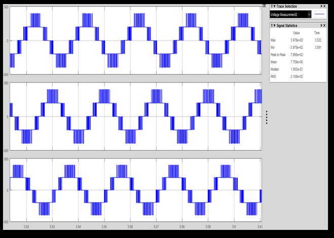
6LinecurrentofSPWMDC-TLIfordifferentloading condition
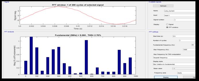
Figure7.FFTgraphforDC-TLIlinecurrent(rms)=6.55A andTHDvalue=2.76%
FFTGraphForDC-TLIlinecurrent(rms)of6.55A isshown inFigure
7 FFTGraphFortwo-levelinverterLinecurrent(rms)=7A isshowninFigure9.
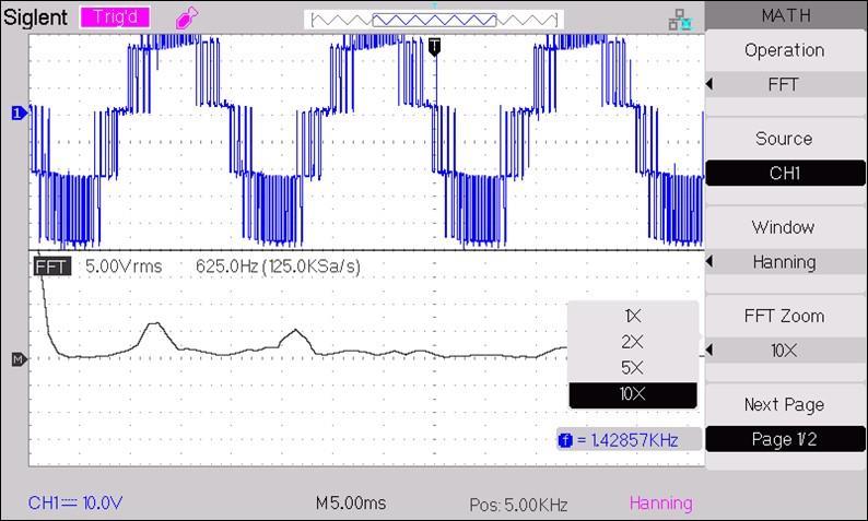
Figure9.FFTgraphfortwo-levelinverterlinecurrent(rms) =7AandTHDValue=10.87%
Table2.Comparisonofpowerqualityinlinecurrenton formofTHD
Threephase SPWMinverter forRL Load
SPWM inverterforRLLoad
4.HardwareresultsonDC-TLISPWMInverter(prototype)
ThepracticalsetupasshowninFigure9usedtovalidatethe solarpowered DC-TLI for grid connection. The rating as simulationresultswithDC-TLIispresentedinhardwarealso. Powerratingisscaledtothefollowingratingduetohardware availability.
InverterInputDCvoltage48V
MaximuminverteroutputAC phasevoltage( Vph ):20V
MaximuminverteroutputAClinevoltage(VL-L ):34
Figure8showsthegatepulseofS1andS1’andFigure
11showsthegatepulseofS1andS4’.Thewaveformofline voltage(VRY)ispresentedinFigure12.Figure13showsFFT Graphforthelinevoltagewaveform.Figure14showsforthe three-levelNPCinvertermodulephasevoltagewaveform. Inverter type
International Research Journal of Engineering and Technology (IRJET) e-ISSN: 2395-0056
Volume: 11 Issue: 08 | Aug 2024 www.irjet.net p-ISSN: 2395-0072
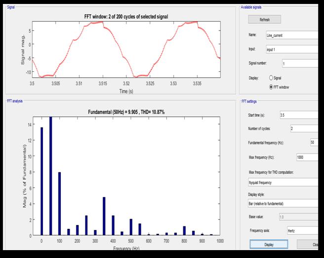
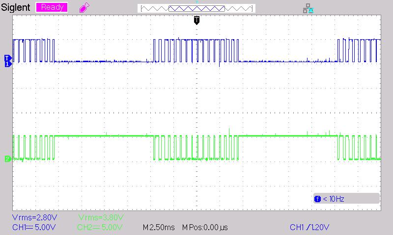
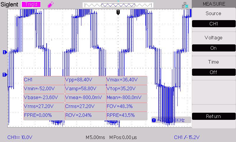
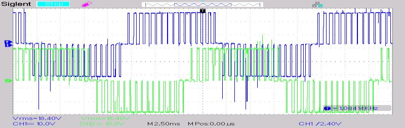
Figure12.ThewaveformofphasevoltagesforDC-TLI
The Resistive (R) Load and Inductive (RL) Load connected withDC-TLIareexperimentallychecked.Resistive(R)Loadof 200ohm,25Wisconnectedandexperimentallycheckedas showninFigure15.Inductive(RL)Loadof(R=200ohm,25W, L=120mH each phase) is connected and experimentally checked as shown in Figure 16. The THD of line current is improvedseeninpracticaltesting.
Figure 13. Load Current in case of Resistive Load (R= 200 Ohm,25W)andFFTgraphforDC-TLI
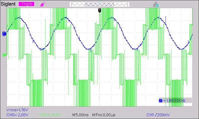
Figure14.DC-TLIwaveformofVoltage(VRY)andcurrent (IR)withRLLoad(IL=0.3A,VL=34V)
Figure 17.Waveform of RL Load Current and FFT window graphforDC-TLI.
4. Conclusion
Thispaperpresentedacomparisonbetweentraditionaltwolevel inverter and DC-TLI for power quality of solar PV systems. Power quality with respect to THD and Harmonic distortion is analysed for DC-TLI module for the solar PV grid. Simulation results of Three-level diode clamped
SPWMVSIsimulationusingMATLABarepresented.FFTgraph and THD values are compared for DC-TLI with two-level inverter line current.The 3-level diode clamped inverter improvesTHDupto2.72%to 2-levelconventionalinverter THD is about 10.87 %. DC-TLI requires only six diode for clamping. As voltage level increases, clamping diode requirementalsoincreases.Three-levelinverters(TLIs)are used to eliminate harmonics and hence the performance of invertersystemofthesolarPVgridisimproved.
International Research Journal of Engineering and Technology (IRJET) e-ISSN: 2395-0056
Volume: 11 Issue: 08 | Aug 2024 www.irjet.net p-ISSN: 2395-0072
Reference:
[1] S. Kumar and C. Sethuraman, “Grid tied inverters for renewableenergysystems-areview,”InternationalJournalof EnvironmentandSustainableDevelopment,vol.21,no.1–2, pp.43–75,2022.
[2]M.VSubramanyam,B.P.Reddy,andP.V.N.Prasad,“THD Analysis for 3-Phase 5-Level Diode Clamped Multilevel InverterUsingDifferentPWMTechniques,”vol.2,no.10,pp. 4121–4129,2013.
[3]H.A.Hamed,F.N.AlMansoori,andE.H.E.Bayoumi,“An effective IGBT driver circuit for three level neutral point clamped converters,” International Journal of Industrial ElectronicsandDrives,vol.4,no.1,pp.25–32,2018.
[4]V.FernãoPires,A.Cordeiro,D.Foito,andJ.FernandoSilva, “Three-phase multilevel inverter for grid-connected distributedphotovoltaicsystemsbasedinthreethree-phase two-levelinverters,”SolarEnergy,vol.174,pp.1026–1034, 2018.
[5]S.Srikanth,“AThreePhaseMultiLevelConverterForgrid Connected PV System,” International Journal of Power ElectronicsandDriveSystems(IJPEDS),vol.5,2014.
[6] U.-M. Choi and J.-S. Lee, “Comparative Evaluation of Lifetime of Three-Level Inverters in Grid-Connected PhotovoltaicSystems,”Energies,vol.13,no.5,2020.
[7]A.Choudhury,“Three-LevelNeutralPointClamped(NPC) Traction Inverter Drive For Electric Vehicles,” Concordia University,Montreal,Canada,2015.