
International Research Journal of Engineering and Technology (IRJET) e-ISSN: 2395-0056
Volume: 11 Issue: 08 | Aug 2024 www.irjet.net p-ISSN: 2395-0072

International Research Journal of Engineering and Technology (IRJET) e-ISSN: 2395-0056
Volume: 11 Issue: 08 | Aug 2024 www.irjet.net p-ISSN: 2395-0072
Sowmya K B1 , Chethan K2
1P.G Student, Department of Civil Engineering, U.V.C.E, Bangalore University, Bengaluru 2 Associate Professor, Department of Civil Engineering, U.V.C.E, Bangalore University, Bengaluru.
Abstract - Prefabricated Prefinished Volumetric Construction (PPVC) is a construction method whereby freestanding 3D modules are completed with internal finishes, fixtures andfittings inanoff-site fabrication facility, before it is delivered and installed on-site. The whole idea is to significantly speed up construction in this traditionally manpower-intensive industry. Inthisdissertationwork,a3DRCbareframestructurehaving conventional beam column system and prefabricated prefinishedvolumetricconstructionsystemarecomparedwith G+10, G+20 and G+30 stories by performing FE analysis involvingmodal,equivalentstatic,responsespectrumanalysis. The results of time period, base shear, storey displacements, storey drifts are obtained. All the results are tabulated, discussed and conclusions are drawn.
Key Words: Modal analysis, Equivalent static analysis, Response spectrum analysis, Flexible loop connectors
Prefabricatedprefinishedvolumetricconstruction(PPVC)is aninnovativeandcleanerapproachthathasrestructuredthe productionoftheconstructionindustry.Itcanimprovethe workflow continuity, increase the efficiency in the use of resources, minimize construction wastes, and reduce the number of on-site contractors as well as construction durations. While the benefits of PPVC have been widely recognized over the past two decades, the constraints on usingPPVCremainsunexplored.
1. 3DRCframewithregularframesystemandPPVC systemareconsideredforseismicloading.
2. PPVCconnectionsaredesignedforseismicloading
3. FE Analysis of the structure is done by Modal, Equivalent Static and Response Spectra Analysis methodsforbothplanandverticalirregularities.
1. Detailed literature review is carried out on the PrefabricatedPrefinishedVolumetricConstruction andPlan&Verticalirregularity.
2. The study is based on the analysis of structural models representing multi-storey buildings with regular frame system and PPVC system are presentedanddiscussedindetail.
3. Basically,sixtypesofmodelsG+10,G+20andG+30 withregularframesystemandPPVCsystem.Forall seismiczonesareconsidered,foreachsuchbuilding modelisconsideredwithcriticalsoiltypes.
Adetailedsummaryofthevariousparametersdefiningthe Prefabricated Prefinished Volumetric construction (PPVC) and Regular frame system (RFS) with plan and vertical irregularitiesineachmodelisalsopresented.
The methodology involved in computing some of these parametersisexplainedandimportantfeatureofthecurrent provisions relating to earthquake resisting design of reinforced concrete lateral forces resisting system are presented.
Thepresentstudyadoptsstructural3Dmodelswithdifferent typesofplanirregularity&verticalirregularity.Theseismic responses of these Prefabricated Prefinished Volumetric constructionbuildingmodelshavebeencomparedwiththat oftheRegularframesystembuildingmodel.Thebaseplan sizehasbeenkeptas30mx30m
6.
Table1: Structural configuration
Description Data
Typeofstructure Special moment resisting RC frame
GradeofConcrete( ) M30
Grade of Reinforcing Steel( ) Fe500
Numberofstoreys G+10,G+20,G+30
International Research Journal of Engineering and Technology (IRJET) e-ISSN: 2395-0056
Volume: 11 Issue: 08 | Aug 2024 www.irjet.net p-ISSN: 2395-0072
StoreytostoreyHeight3.0m
BottomstoreyHeight 3.0m
SpanLength 5m
Column Size used for PPVCsystem.
2no’sof300x600(10floors),
2 no’s of 400X800mm(20 & 30floors)
Column Size used for RFsystem
600x600(10floors)
800X800mm(20&30floors)
BeamSizeused
400x600(Allfloors), ThicknessofSlab 150mm
LiveLoad 3kN/m²
FloorFinishLoad 1.5kN/m²
SeismicZone V
Seismic Zone Factor (Z) 0.36
Importance
SoilType Softsoil LoadCombination
(DL+LL)
(DL+LL EQ)
(DL EQ)
1.5EQ
Table2: Building Nomenclature
Nomenclature Description
R10 Regularframesystemof10floors
R20
R30
P10
P20
P30
Regularframesystemof20floors
Regularframesystemof30floors
Prefabricatedprefinished volumetricconstructionsystemof 10floors
Prefabricatedprefinished volumetricconstructionsystemof 20floors
Prefabricatedprefinished volumetricconstructionsystemof 30floors
RPI10
RPI20
RPI30
PPI10
PPI20
PPI30
RVI10
RVI20
RVI30
PVI10
PVI20
PVI30
Regularframesystemof10floors withplanirregularity
Regularframesystemof20floors withplanirregularity
Regularframesystemof30floors withplanirregularity
Prefabricatedprefinished volumetricconstructionsystemof 10floorswithplanirregularity
Prefabricatedprefinished volumetricconstructionsystemof 20floorswithplanirregularity
Prefabricatedprefinished volumetricconstructionsystemof 30floorswithplanirregularity
Regularframesystemof10floors withverticalirregularity
Regularframesystemof20floors withverticalirregularity
Regularframesystemof30floors withverticalirregularity
Prefabricatedprefinished volumetricconstructionsystemof 10floorswithverticalirregularity
Prefabricatedprefinished volumetricconstructionsystemof 20floorswithverticalirregularity
Prefabricatedprefinished volumetricconstructionsystemof 30floorswithverticalirregularity
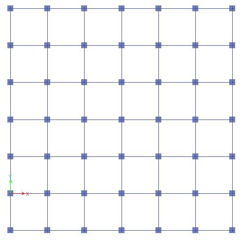
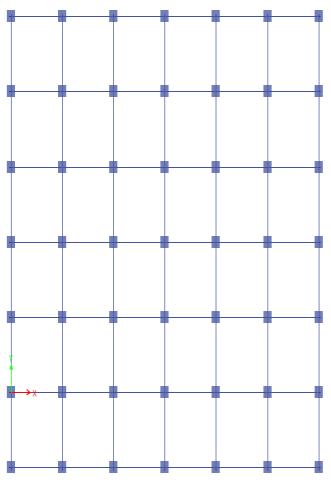
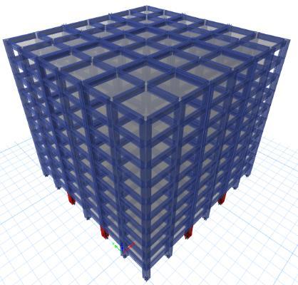
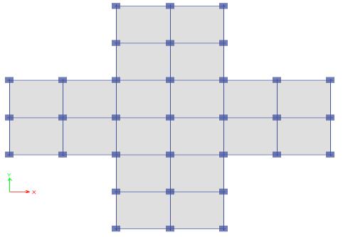
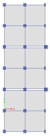
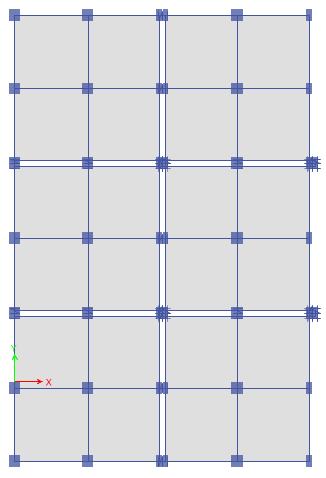
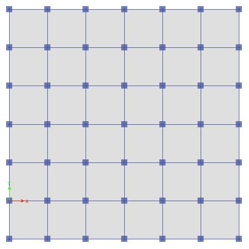
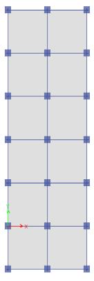
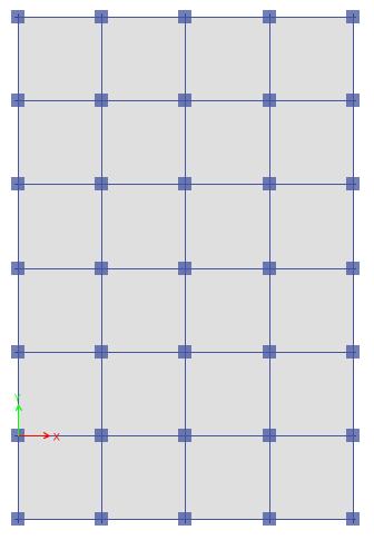
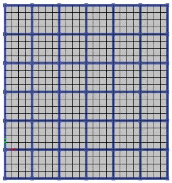
PlanofBareFrameStructuremodelcreatedinsoftwareas showninfigure1&2below.
International Research Journal of Engineering and Technology (IRJET) e-ISSN: 2395-0056
Volume: 11 Issue: 08 | Aug 2024 www.irjet.net p-ISSN: 2395-0072
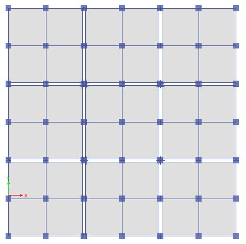
Fig 2: Plan of PPVC for G+10, G+20, G+30 Storey.
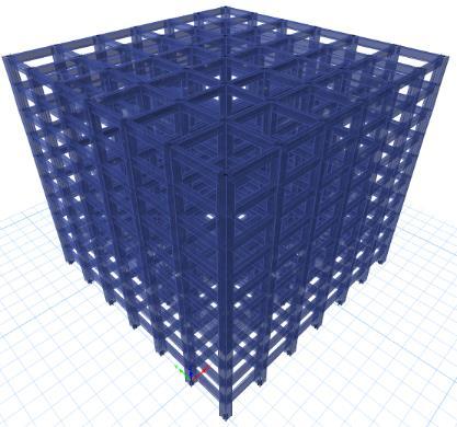
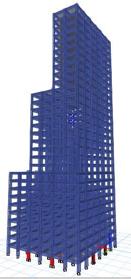
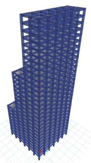
3DviewofBareFramestructuremodelcreatedin softwareasshowninfigure3below.
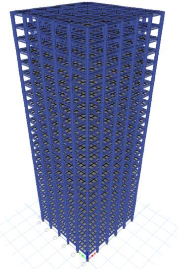
Fig 3: 3D view of G+10,G+20 and G+30 model
a) Building model with PPVC System
Plan, 3D View of bare frame reinforced concrete structure G+10(P10), G+20(P20) and G+30(P30) with PPVC System createdinsoftwareasshownbelow
b) Building model with RFS System
Plan,3D View of bare frame reinforced concrete structure G+10(R10), G+20(R20) and G+30(30) with RFS System createdinsoftwareasshownbelow.
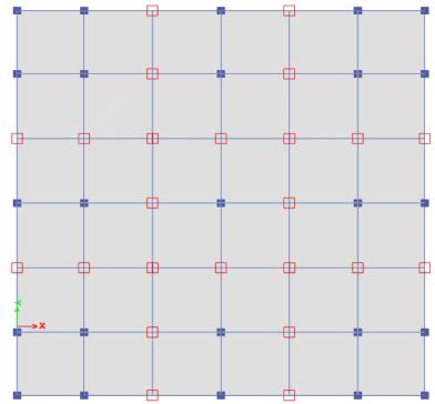
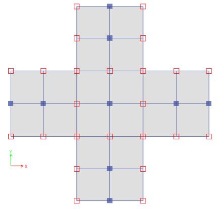
c) Building model with PPVC System with Plan Irregularity
Plan, 3D View of bare frame reinforced concrete structure G+10(PPI10), G+20(PPI20) and G+30(PPI30) with PPVC SystemwithPlanIrregularitycreatedinsoftwareasshown below.
d) Building model with RFS System with Plan Irregularity
Plan, 3D View of bare frame reinforced concrete structure G+10(RPI10),G+20(RPI20)andG+30(RPI30)withRFSystem withPlanIrregularitycreatedinsoftwareasshowninbelow.
International Research Journal of Engineering and Technology (IRJET) e-ISSN: 2395-0056
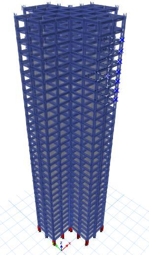
e) Building model with PPVC System with Vertical Irregularity
Plan, 3D View of bare frame reinforced concrete structure G+10(PVI10), G+20 PVI20), and G+30 (PVI30), with PPVC System with Vertical irregularity is created in software as shownbelow.
f) Building model with RFS System with Vertical Irregularity
Plan, 3D View of bare frame concrete structure G+10 (RVI10),G+20(RVI20)andG+30(RVI30)withRFSSystem withVerticalirregularityiscreatedinsoftwareasshown below
Volume: 11 Issue: 08 | Aug 2024 www.irjet.net p-ISSN: 2395-0072 © 2024, IRJET | Impact Factor value: 8.315 | ISO 9001:2008 Certified Journal | Page459
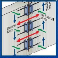
Vertical Modules Connection
Theverticalmodulesconnectioniscrucialforthe structuralbehaviourspeciallyforhighrisebuildings.
Verticaljointsaretobedesignedforeccentricityor imperfectioninaccordancewiththeBuildingCode Requirement.
Horizontal Modules Connection
The horizontal modules connection forming the floor diaphragm, are contribute to the overall buildingstiffness.
The peripheral ties and internal ties shall be providedaspertheBuildingCodeRequirement
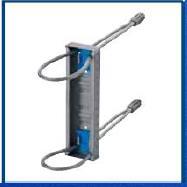
PPVC LINK CONNECTIONS
StructuralAnalysisforLinkConnector(ETABS3DAnalysis Software)
Toanalyzetheconnectionforcesinducedinflexible loopconnector.
International Research Journal of Engineering and Technology (IRJET) e-ISSN: 2395-0056
ToSeebuildingbehaviorandtocheckprovisionof tierequirements.
Flexibleloopconnectorsaremodelledasnonlinear linkwithtensiononly.
DesignCapacityoflink connectorunder tension= 18kN
Design Capacity of link connector under shear = 27kN
Volume: 11 Issue: 08 | Aug 2024 www.irjet.net p-ISSN: 2395-0072 © 2024, IRJET | Impact Factor value: 8.315 | ISO 9001:2008 Certified Journal | Page460
Designresistanceofflexibleloopconnectorfor PPVCproject
wall/colu mn thickness
Outof plane shear(k N/BOX) Inplane shear(kN/B OX)
Direct tensile forces(kN/B OX)
>200 mm 6 27 18
8. FEM ANALYSIS
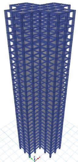
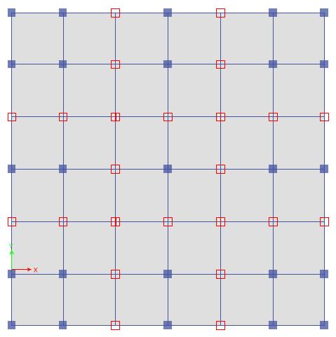
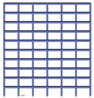
Step by step procedure for all methods of analysis is performed in this project work is explained. Figs 5 shows plan,elevationand3Dviewofregularframestructuralmodel fromETABS.
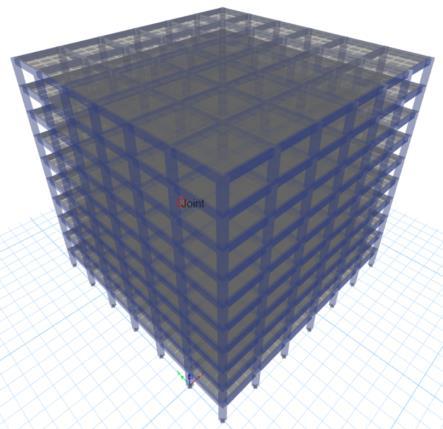
Fig 5: Plan, Elevation and 3D View of Regular structural model
CROSS SECTIONAL PROPERTIES AND MATERIAL CONSTANTS:
Thecross-sectionalpropertiesofmembersofinfilledframe consideredforthestudyareasfollows.
Compressive strength of concrete 30MPa
Characteristicstrengthof ReinforcingSteel 500MPa
Modulus of elasticity of concrete 2738613MPa
Modulus of elasticity of steel 2.0x10⁸ kN/m2
Densityofconcrete 250kN/m3
Densityofsteel 785kN/m3
Poisson’s Ratio for concrete 02
Poisson’sRatioforsteel 03
International Research Journal of Engineering and Technology (IRJET) e-ISSN: 2395-0056
Volume: 11 Issue: 08 | Aug 2024 www.irjet.net p-ISSN: 2395-0072
LOADS:
Threetypesofloadsareasfollows:
1.Deadload
2.Liveload
3.Earthquakeload(inX-directionandY-direction)
LINEAR DYNAMIC ANALYSIS:
Seismic Coefficients:
SeismicZoneFactor:Z=0.36
Soiltype:Mediumsoil(Type–II)
ImportanceFactor:I=1(SpecialMomentResistingFrame)
ResponseReductionFactor:R=5
Timeperiod(T) :Programcalculated.
Thefundamentaltimeperiodforallmodelsisobtainedfrom themodalanalysis,whichcalculatesthetimeperiodonthe basisofmassandstiffnessofthestructure.IS1893(PartI): 2016givestheempiricalformulaforcalculatingthenatural timeperiodwithoutmasonryinfill.i.e,
Ta=0.075h0.75
Wherehisthetotalheightofthebuilding.
ForG+10;Ta=0.075x300.75 =0.96sec
ForG+20;Ta=0.075x600.75 =1.62sec
ForG+30;Ta=0.075x900.75 =2.19sec
Fundamental time period calculated by modal analysis resultsaretabulatedinTable6.1andthegraphshowingtime periodversusmodelsareshowninFig6.1
Table 4: Time period (s)
BUILDING
P30 5.26 RPI30 5.337
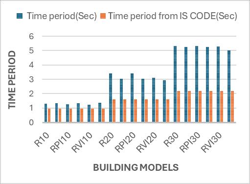
Fig 6 Time period
FromTable4andFig6thefollowingobservationsaremade.
1. As per IS 1893:2016 there is no consideration of irregularityinthecode.Timeperiodwillvaryonly withtheheightofstructuresforallthemodels.
2. As the height increases, timeperiod increases as theweightofthestructureincreases.
3. The codal time period does not match with the modalanalysisresultshighlightingthedeficiencyof the code. Time period obtained from dynamic analysisforPPVC&RFSmethodaremorecompared tocodalmethodforalltheloadcases.
International Research Journal of Engineering and Technology (IRJET) e-ISSN: 2395-0056
Volume: 11 Issue: 08 | Aug 2024 www.irjet.net p-ISSN: 2395-0072
6.2 RESPONSE SPECTRUM ANALYSIS
Responsespectrumanalysisofstructureiscarriedoutforthe
seismic zone V, as per IS 1893-2016, using the response spectrumgenerated.Baseshear,Displacement,Inter-storey drift are obtained for all the models are discussed in this section.
Scale factor is defined as the ratio of static base shear to dynamicbaseshear,theratiothisobtainedisusedinfurther partofdynamicanalysisandshowninTable5andthegraph showingcorrectedbaseshearversusmodelsareshowninFig 7.
Scalefactor=

7 Corrected dynamic Base shear (kN)
6.2.2 Corrected Dynamic Base Shear (kN)

Scalefactor(RF)= =0.94
Table 5 Scale Factor
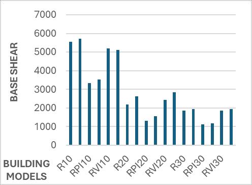
Table 6 Corrected Dynamic Base Shear (EQ Loads)
DESIGNEDBUILDING FLOORS CORRECTEDBASESHEAR RSPX/RSPY R10 5547 P10 5718
RPI10 3334
PPI10 3517
RVI10 5209
PVI10 5130
R20 2187
P20 2622
RPI20 1304
PPI20 1554
RVI20 2438
PVI20 2840
R30 1868
P30 1930
RPI30 1114
PPI30 1187
RVI30 1863
PVI30 1932
FromTable5&6andFig6thefollowingobservationsare made.
1) As the height of the building increases there is a decrease in the base shear due to the increase in timeperiod.
International Research Journal of Engineering and Technology (IRJET) e-ISSN: 2395-0056
Volume: 11 Issue: 08 | Aug 2024 www.irjet.net p-ISSN: 2395-0072
2) AsthereisadecreaseintheconsideredPlanarea, Base shear of RFS and PPVC System with plan irregularity is less compared with other buildings irrespectiveofnumberoffloorsduetolesserweight.
3) PPVC models have higher baseshear forall floors moreduetothestiffnessofferedbydualcolumns.
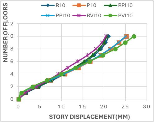
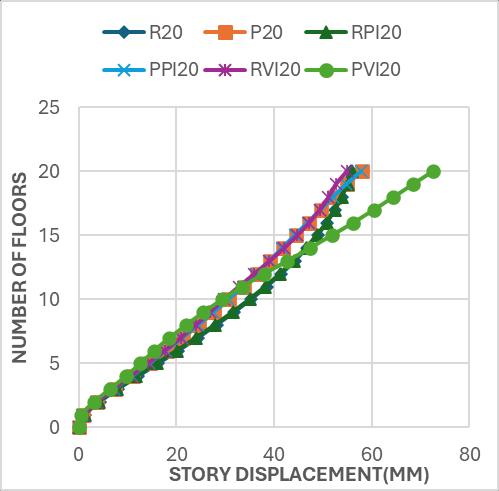
The results of G+10, G+20 & G+30 buildings are shown in table7,8&9respectively.Theplotofdisplacementversus storeyforRFSandPPVCwithplanandverticalirregularity modelsareshowninFig8,9&10respectively.
Table 7 Storey Displacement (mm) of G+10 with Plan & Vertical irregularity
International Research Journal of Engineering and Technology (IRJET) e-ISSN: 2395-0056
Volume: 11 Issue: 08 | Aug 2024 www.irjet.net p-ISSN: 2395-0072
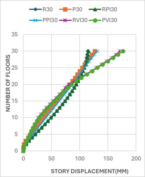
10 Storey Displacement for G+30 Building
Table 9 Storey Displacement (mm) of G+30 with Plan & Vertical irregularity
From the table 7,8 & 9 and fig 8,9 & 10 the following observationsaremade.
1. Astheheightofthebuildingincreasesthereis anincreaseinthestoreydisplacement. DESIGNED
International Research Journal of Engineering and Technology (IRJET) e-ISSN: 2395-0056
Volume: 11 Issue: 08 | Aug 2024 www.irjet.net p-ISSN: 2395-0072
2. Due to vertical irregularity, displacement has increased due to reduction in weight of structure.
3. Due to plan irregularity, displacement varies duetoreductioninthestiffnessofstructure
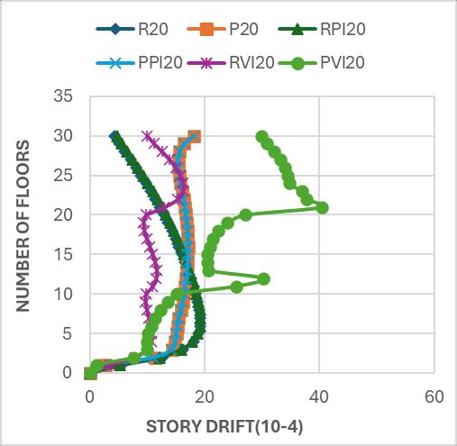
6.2.3 Storey Drift
Theplotofstoreydriftvs.storeyheightforPPVCandRFS modelsareshowninFig11,12&13respectively.Table10, 11&12showthemaximumdriftformodelsinzoneV.
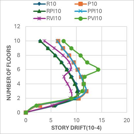
Table 10 Storey Drift (10-4) of G+10 with Plan & Vertical irregularity.
DESIGNED
Table 11 Storey Drift (10-4) of G+20 with Plan & Vertical irregularity.
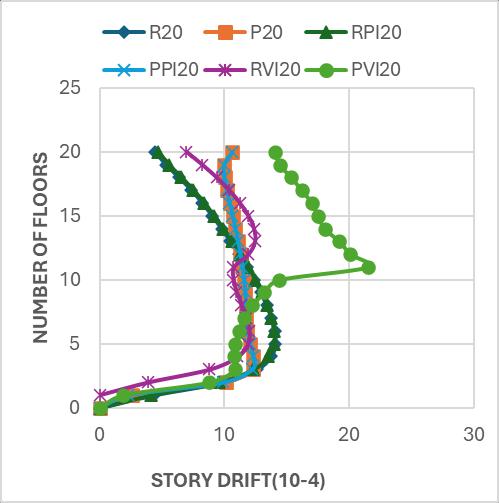
12 Storey Drift for G+20 Building
International Research Journal of Engineering and Technology (IRJET) e-ISSN: 2395-0056
Volume: 11 Issue: 08 | Aug 2024 www.irjet.net p-ISSN: 2395-0072
DESIGNED BUILDING FLOORS
Fromtabletable10,11&12andfig11,12&13following observationsaremade:
1. Duetothesuddendecreaseintheareaat5th floor thereisaincreaseinthestorydrift.
2. Thepresenceofverticalirregularitiesatthe10th, 20th,and30thfloorsresultedinasignificantrise instoreydriftduetoreducedstructuralstiffness.
3. Storeydriftofallmodelsiswithinthepermissible limits i.e 0.004 times the storey height as per IS 1893-2016.
1. ThedesignofPPVCLinkConnectionsisdoneusing softwares.
2. The Torsional irregularity, Re-entrant corner irregularity and soft storey check is done and observedresultsareSAFEasperISCode.
3. As per IS 1893:2016 there is no consideration of irregularityinthecode.Timeperiodwillvaryonly withtheheightofstructuresforallthemodels.
4. Astheheightincreases,timeperiodincreasesasthe weightofthestructureincreases.
5. The codal time period does not match with the modalanalysisresultshighlightingthedeficiencyof the code. Time period obtained from dynamic analysis for PPVC & RFS method are more comparedtocodalmethodforalltheloadcases.
6. As the height of the building increases there is decrease in the base shear due to the increase in timeperiod.
7. AsthereisadecreaseintheconsideredPlanarea, Base shear of RFS and PPVC System with plan irregularity is less compared with other building irrespective of number of floors due to lesser weight.
8. PPVCmodelshavehigherbaseshearforallfloors moreduetothestiffnessofferedbydualcolumns.
9. Astheheightofthebuildingincreasesthereisan increaseinthestoreydisplacement.
International Research Journal of Engineering and Technology (IRJET) e-ISSN: 2395-0056
Volume: 11 Issue: 08 | Aug 2024 www.irjet.net p-ISSN: 2395-0072
10. Due to vertical irregularity, displacement has increasedduetoreductioninweightofstructure. 11. Duetoplanirregularity,displacementvariesdueto reductioninthestiffnessofstructure.
12. Duetothesuddendecreaseintheareaat5th floor thereisaincreaseinthestorydrift.
13. Thepresenceofverticalirregularitiesatthe10th, 20th,and30thfloorsresultsinasignificantrisein storeydriftduetoreducedstructuralstiffness.
14. Storeydriftofallmodelsarewithinthepermissible limits i.e 0.004 times the storey height as per IS 1893-2016.
15. By Looking into my analysis results, PPVC can improve productivity by up to 40% in terms of manpower and time savings, depending on the complexityoftheprojects.
1. Ali Tighnavard Balasbaneh, Mohd Zamri Ramli, Mohammad Hossein Taghizadeh Valdi3(2021),” Comparing Different Concrete Construction Techniques: Modular versus Individual Panel System Methods”,Proceedings of the 11th Annual InternationalConferenceonIndustrialEngineering andOperationsManagementSingapore.
2. ChuaaY.S,J.Y.R.Liewa,bandS.D.Panga(2018),” RobustnessofPrefabricatedPrefinishedVolumetric Construction (PPVC) High-rise Building” , 12th International Conference on Advances in SteelConcreteCompositeStructures(ASCCS2018)
3. Devesh P. Soni and Bharat B. Mistry, “Qualitative review of seismic response of vertically irregular building frames” ISET Journal of Earthquake Technology, Technical Note, Vol. 43, No. 4, December2006.
4. LiYS,BGHwang,MShanandKYLooi4(2019),” Developing a Knowledge-based Decision Support System for Prefabricated Prefinished Volumetric Construction”, OP Conf. Series: Earth and EnvironmentalScience.
5. MarkLawson.R,M.ASCE;RayG.Ogden;andRory Bergin(2012) , “Application of Modular Construction in High-Rise Building”, /Journal of Architecturalengineering©ASCE
6. Mahinur Hossain(2019),” IPS & PPVC Precast System in Construction- A Case Study in SingaporeanHousingBuildingProject”,Journal of SystemandManagementSciencesVol.9(2019)No. 2,pp.23-42
7. Pawade R. R. and M. N. Mangulkar, “Influence of CombineVerticalIrregularitiesintheResponseof Earthquake Resistance Rc Structure Influence of CombineVerticalIrregularitiesintheResponseof Earthquake Resistance Rc Structure,” no. August, 2017.
8. SzeDaiPANG1,JYRichardLiew2,ZiquanDai3and Yanbo Wang4(2016),” Prefabricated Prefinished Volumetric Construction Joining Techniques Review” , 2016 Modular and Offsite Construction (MOC)SummitEdmonton,Alberta,Canada.
9. Suhanth Reddy.K, CH.Rajesh, Mrs. P. Srilakshmi(2017)”AnalysisofConventionalBeam ColumnSystemoverRCStructuralWallSystemin Multi Storey Building” , International Journal & MagazineofEngineering,Technology,Management andResearch.
10.Sayyed O., S. S. Kushwah, and A. Rawat, “Seismic Analysis of Vertical Irregular RC Building with Stiffness and Setback Seismic Analysis of Vertical Irregular RC Building with Stiffness and Setback Irregularities,”no.April2018,2017