
International Research Journal of Engineering and Technology (IRJET) e-ISSN: 2395-0056
Volume: 11 Issue: 08 | Aug 2024 www.irjet.net p-ISSN: 2395-0072

International Research Journal of Engineering and Technology (IRJET) e-ISSN: 2395-0056
Volume: 11 Issue: 08 | Aug 2024 www.irjet.net p-ISSN: 2395-0072
M. Anukeerthana1, Dr.G.Kavithaa2
1PG Scholar, Department of Electronics and Communication Engineering, Government College of Engineering –Salem-11, Tamil Nadu, India
2Associate Professor, Department of Electronics and Communication Engineering, Government College of Engineering – Salem-11, Tamil Nadu, India
ABSTRACT: The research paper presents a rectangular microstrip antenna that was simulated and constructed to improve marine communication demands. This communication antenna performs consistently in harsh maritime environments. This study focuses on designing and optimizing a rectangular microstrip patch antenna for navy applications in the very high frequency (VHF) band. The antenna has a length of 441.6 mm, a width of 563.9 mm, a permittivity of 4.4, and a height of 2.0 mm. The patch and ground plane are made of copper. This uses the High FrequencyStructureSimulator(HFSS)softwareandoperates with a return loss of -20.1860 db. The results illustrate an efficientdesignwithgoodimpedance matchingandradiation properties, making it a feasible alternative for maritime communication applications. The performance of the patch antenna was evaluated using several antenna characteristics such as return loss (S11), directivity, gain, bandwidth, VSWR radiation pattern, antenna efficiency, and input impedance.
Keywords: ANSYS HFSS (high-frequency structure simulator),(VSWR)voltagestandingwaveratio,(VHF)Very high frequency, (MHz) megahertz, (RL) return loss, (RPA) rectangularmicrostrippatchantenna,(FR4)flameretardant forwovenglassreinforcedepoxyresin.
Anantennaisatransmitterthatconvertselectricalsignalsto electromagneticwavesandviceversa.Anantennaisadevice designed to broadcast or receive electromagnetic waves successfully. It is often composedof conductive materials suchasmetal rods, wires, orprinted circuits thatinteract with the electromagnetic field to achieve the intended transmission or reception. Microstrip antennas were first introducedinthe1950s.However,ittookalmost20years forthisvisiontobecomeareality,withtheintroductionof printed circuit board (PCB) technology in the1970s. Becauseoftheirsmallsize,microstripantennashavefound use in a variety of civilian and military applications, includingradio-frequencyidentification(RFID),broadcast radio,mobilesystems,vehiclecollisionavoidancesystems, satellite communications, surveillance systems, direction finding, radar systems, marine communication remote sensing,missileguidance,andothers.Inmicrostripantenna
research, a new trend or solution emerges in which researcherstrytoincreasebandwidthbyincorporatingnew featuresintotheantennaform.Demandforbroadband,lowprofile,andsmallantennashasgrowndramaticallyinrecent years due to the widespread deployment of wireless communicationtechnology.Becauseofitslowprofile,light weight,andaffordableprice,themicrostrippatchantenna hasbeensuggestedasasolutiontomeettherequirements. Marinecommunicationisacriticalcomponentofmaritime operations,ensuringthesafety,coordination,andefficiency ofactivitiesatsea.Themaritimeindustryreliesheavilyon robust and reliable communication channels to connect ships with each other and with shore-based facilities. EffectiveVHFantennasaregreaterindemandbecauseofthe increasing significance of dependable marine communication,especiallyinnavigation,safety,andsearch andrescueoperations.Becauseofitssmallsize,lightweight, and durability, this paper focuses on the design and optimizationofarectangularmicrostrippatchantennafor marinecommunicationat156MHz,astandardfrequencyfor VHF maritime radio systems. The FR4 epoxy substrate provides a good blend of cost-effectiveness, mechanical durability,andacceptabledielectriccharacteristics,witha relativepermittivity(εr)of4.4andathicknessof2.0mm.
Table-1: Marineapplicationfrequencybands
Frequency Band Range Primary Applications
VHF-VeryHigh
Frequency 30-300 MHz Distress and safety communication(e.g., Channel 16 on 156.800MHz),intershipcommunication, port operations, and bridge-to-bridge communication.
Channels 6, 13, and 70areoftenused
HF-HighFrequency 3 - 30 MHz wide-range communication, including ship-toshore and intership
International Research Journal of Engineering and Technology (IRJET) e-ISSN: 2395-0056
communication over great distances, GMDSS (Global Maritime Distress and Safety System) frequencies, such as 2182kHzfordistress andsafety.
MF-Medium Frequency
LF-LowFrequency
3003000kHz Frequencies such as 2182kHzaremostly utilized for distress and safety communication on ships. Also used for navigation and coastal communication.
30 - 300 kHz Usedfor navigationalaids, especiallymarine nauticalbeacons, andoccasionallyfor maritime communicationin specificzones.
UHF-UltraHigh Frequency
3003000 MHz Typicallyutilizedfor port operations, onboard communications,and some specific applications such as navigationalaidsand digital communication systems.
VHF (Very High Frequency) is superior for marine communicationtootherfrequencybandsduetoseveralof major features. To begin, VHF delivers optimal range and clarity, allowing for smooth voice communication at distancesofupto20-30mileswhilebeinglessinfluencedby atmospheric noise and interference. VHF signals' line-ofsight propagation is suitable for broad seas with low obstructions,makingthemusefulforbothship-to-shipand ship-to-shorecommunications.VHFradiosalsoofferspecial distress and safety channels, such as Channels 16 and 70, which allow for speedy and dependable communication during an emergency. In addition, VHF radios are small, power-efficient, and appropriate for many types of watercraft,fromsmallboatstohugeships.VHFisrequired by international maritime laws, particularly those of the International Maritime Organization (IMO), to provide uniformityandinteroperabilityamongvesselsworldwide. Finally,VHFislesscongestedthanlowerfrequencybands, resulting in more dependable transmission without
interference.ThesepropertiesmakeVHFthebestchoicefor navalcommunication,sinceitsuccessfullybalancesrange, clarity,andreliability.
The primary objective of this paper is to create a highly efficient and dependable rectangular microstrip patch antenna for marine communication at 161.77 MHz. The ultimategoalistoimprovethereliabilityandefficiencyof marinecommunication,whichwillimproveglobalmaritime safety,coordination,andoperationalefficiency.Thisstudy seekstopresenta reliable, cost-effectiveantenna solution thatmaybewidelyused,therebycontributingtothegrowth ofmarinecommunicationtechnology.
ANSYS HFSS is a 3D electromagnetic (EM) simulation software that allows you to design and simulate highfrequency electronic devices such asantennas, antenna arrays, RF or microwave components, high-speed interconnects,filters,connectors,ICpackages,andprinted circuitboards.AnsysHFSSsoftwareisusedbyengineersall around the world to design high-frequency, high-speed circuits for communications systems, advanced driver assistancesystems(ADAS),satellites,andinternet-of-things (IoT) products. ANSYS HFSS (High-Frequency Structure Simulator)isapowerfulsimulationtoolusedtobuildand analyze high-frequency electromagnetic structures in industriessuchastelecommunications,aerospace,defense, andelectronics.Itoffers3Dfull-waveelectromagneticfield simulation utilizing the finite element technique (FEM) to accuratelymodelcomplicatedstructuressuchasantennas, RF/microwave components, PCBs, and IC packages. HFSS containspowerfuloptimizationtools,S-parameteranalysis, andfull-waveandeigenmodesolvers,makingitcriticalfor understanding the performance of RF and microwave devices.ItworkssmoothlywithotherANSYStoolsandthirdparty software, providing a streamlined workflow for multiphysics simulations that combine electromagnetic, thermal, and structural assessments. HFSS uses highperformance computing (HPC) capabilities to efficiently handlelarge-scalemodels.Itsapplicationsincludeantenna designandoptimization,analysisofsignalintegrity,power integrity, and electromagnetic interference (EMI) in PCBs and IC packages, and the development of wireless communication systems such as 5G and satellite communications. The software ensures that the design process is accurate, reliable, and efficient, eliminating the need for physical prototypes and experiments and, as a result, lowering development costs and promoting innovationinhigh-frequencydomains.
Volume: 11 Issue: 08 | Aug 2024 www.irjet.net p-ISSN: 2395-0072 © 2024, IRJET | Impact Factor value: 8.315 | ISO 9001:2008
International Research Journal of Engineering and Technology (IRJET) e-ISSN: 2395-0056
Volume: 11 Issue: 08 | Aug 2024 www.irjet.net p-ISSN: 2395-0072
4.1
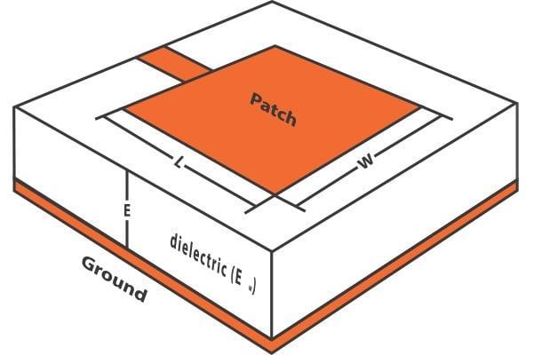
Arectangularmicrostrippatchantennaisidealformarine applications due to its small size, lightweight design, and abilitytobeeasilyfittedintovesselsurfaces.Theseantennas are frequently used in communication systems for navigation,ship-to-shipandship-to-shorecommunication, aswellassatellitecommunication.Arectangularmicrostrip patchantennaformarineapplicationsconsistsofacopperor other conductive metal patch attached on one side of a dielectricsubstrate.Thesubstrate,whichdividesthepatch from the ground plane on the opposite side, is typically constructedofmarine-compatiblematerialssuchasFR4or Rogers.Thegroundplaneactsasareferenceanddirectsthe radiation from the patch. The antenna is powered by a microstriplineorcoaxialprobe,whichexcitesthepatchand detects the input impedance. The rectangular microstrip patchantenna'slowprofileallowsittobeeasilyfixedonthe vessel's deck, mast, or other elements without severely affectingaerodynamics or adding weight. Its ease of production and integration with existing marine communicationsystemsmakeitanexcellentalternativefor improving ship navigation, safety, and communication capabilities.
Edge feeding is a typical approach for activating a rectangular microstrip patch antenna, which is especially usefulinmarineapplicationswherespaceand integration arecrucial.Inthis method, thefeed mechanism,suchasa microstriplineorcoaxialprobe,isplacedalongtheedgeof therectangularpatch.Thismethodallowsformoreefficient signalcouplingandimpedancematching,whichiscriticalfor improvingantennaperformance.Edgefeedingcontributesto a wider bandwidth and improves the antenna's radiation properties, making it appropriate for reliable marine
communication. Its design advantages include a small footprintandeaseofinstallation,makingitperfectforships withlimitedroom.Furthermore,choosingpropersubstrate materials and protective coatings guarantees that the antenna can endure harsh marine circumstances, such as seawaterexposure.
Table-2: Dimensionsofproposedantenna
Name of the parameters
LengthoftheSubstrate(Ls) 563.9mm
WidthoftheSubstrate(Ws) 441.6mm
LengthofthePatch(Lp) 883.2mm
WidthofthePatch(Wp) 1127.8mm
Relative permittivity of the substrate (FR4),ɛr 4.4mm
HeightoftheSubstrate(Hs) 2.0mm
LengthoftheFeedline(Lf ) -211.5mm
WidthoftheFeedline(Wf ) 5mm
WidthoftheGround(Wg) 1127.8mm
LengthoftheGround(Lg) 883.2mm
C=3x10⁸
fo =161.770MHz
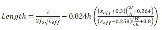
5.1DESIGNFORMULA
Widthofthepatch, [1]

Lengthofthepatch, [2]
WidthoftheSubstrate,
Ws=6h+w [3]
LengthoftheSubstrate
LS = 6h+L [4]
International Research Journal of Engineering and Technology (IRJET) e-ISSN: 2395-0056
Volume: 11 Issue: 08 | Aug 2024 www.irjet.net p-ISSN: 2395-0072
LengthoftheGround
Lg = L+6h [5]
WidthoftheGround
Wg=w+6h [6]
Where,
cisthevelocityoflight
f0 isresonantfrequency,
ɛristherelativepermittivity
ɛreffistheeffectiverelativepermittivity,
hheightofsubstrate
Wisthewidthofthesubstrate.
5.2DESIGNCALCULATIONOFPROPOSEDANTENNA
Fromtheequation[1],Widthofthepatch,Wp=563.9mm
Fromtheequation[2],Lengthofthepatch,Lp=441.6mm
Fromtheequation[3],Widthofthesubstrate,Ws=1127.8 mm
From the equation [4], Length of the substrate, Ls = 883.2 mm
Fromtheequation[5],Widthoftheground, Wg=1127.8mm
Fromtheequation[6],Lengthoftheground,Lg=883.2mm
Widthofthefeedline,Wf=5mm
Lengthofthefeedline,Lf=-211.5mm
Heightofthesubstrate,Hs=2.0mm
Relativepermittivityofthesubstrate(FR4),ɛr=4.4
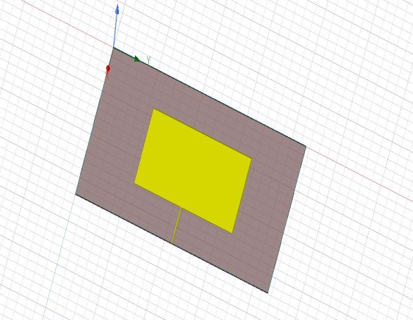
6. PROPOSED ANTENNA DESIGN
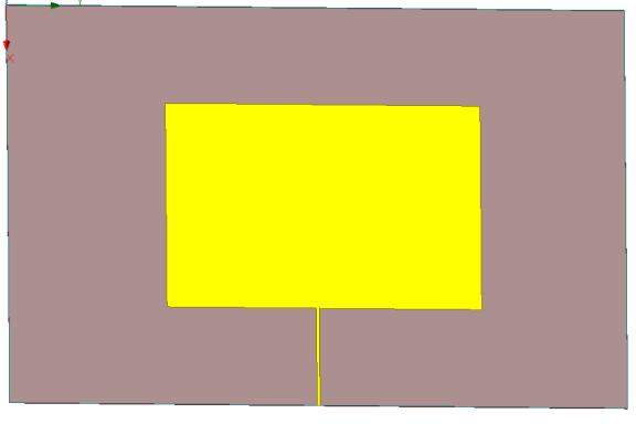
The design of a rectangular microstrip patch antenna at theoperating frequency of 161.77 MHz in very high frequency(VHF)usingFR4epoxysubstrate.Thepatchhas alengthof441.6mm,awidthof563.9mm,permittivityof 4.4,andaheightof2.0mmsandwichedbetweenthepatch andgroundplanemadeupofcopper.
7. RESULT IN HFSS SOFTWARE
Right-click on the project manager results. Choose to generate a data report for Modal Solutions. Decide on a rectangleplot.AfterselectingtheSparameter,clickS(1,1) andthen dB.Choose"New Report."Itshowsa returnloss plot.PlotsarecreatedinthesamemannerforVSWR,gain, directivity,andradiationpattern.
International Research Journal of Engineering and Technology (IRJET) e-ISSN: 2395-0056

Fig-4 Return loss
ReturnLoss(s11)Importance:Lowerreturnlossindicates better impedance matching, which means more power is transmitted while less is reflected. Typical values: A return loss of -10 dB or less (more negative) is usually considered satisfactory. Proposed return loss: This antenna's return loss was20.1860db.
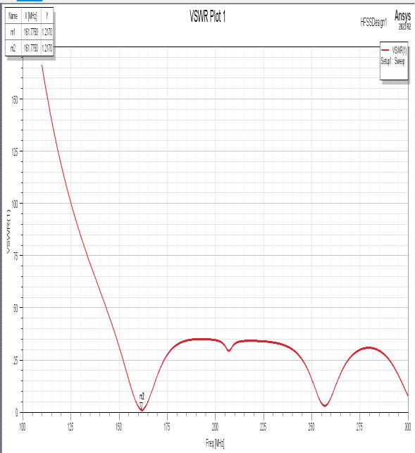
Fig-5 Voltage standing wave ratio
VSWR (Voltage Standing Wave Ratio) Importance: VSWR is defined as the ratio of maximum voltage to minimum voltage in a standing wave pattern on a transmissionline.Itiscommonlystatedasaratio,suchas
2:1,orasasinglenumber,like2.TheoptimumVSWRisone, indicating perfect impedance matching with no reflected power.VSWRisproportionaltothereflectioncoefficient(Γ), which is the percentage of incident power reflected back fromtheload.VSWRiscriticalforachievingefficientpower transfer and avoiding power loss. High VSWR can cause power loss, signal distortion, and transmitter damage. Typicalvalues:
LowerVSWRimpliesbettermatching,withavalueranging from1to2.
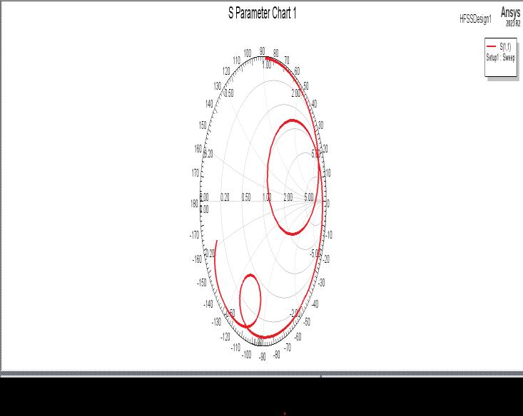
A Smith Chart is a graphical representation used to solve problemsinvolvingtransmissionlinesandmatchingcircuits. Itrepresentstheplotofcomplexreflectioncoefficients(S11) orimpedance.
Volume: 11 Issue: 08 | Aug 2024 www.irjet.net p-ISSN: 2395-0072 © 2024, IRJET | Impact Factor value: 8.315 | ISO 9001:2008 Certified
International Research Journal of Engineering and Technology (IRJET) e-ISSN: 2395-0056
Volume: 11 Issue: 08 | Aug 2024 www.irjet.net p-ISSN: 2395-0072
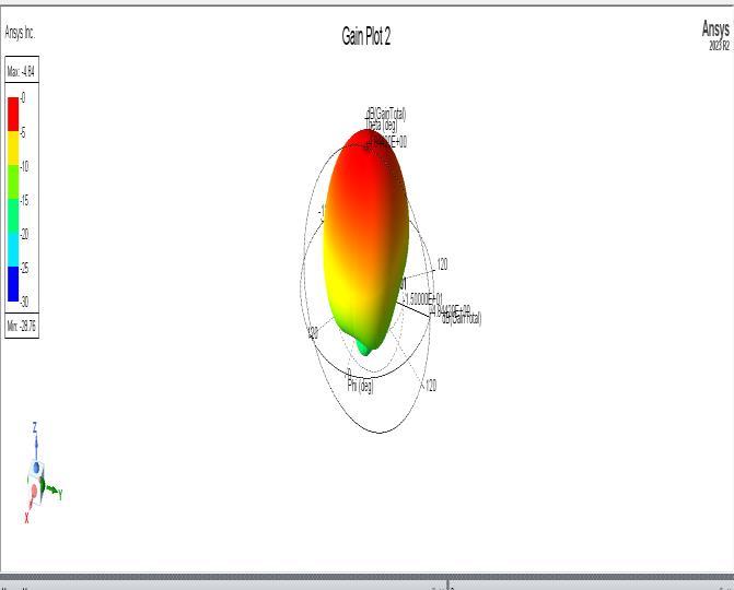
This graphic illustrates the antenna gain in three dimensions,demonstratinghowpowerisemittedinvarious directions. It provides a full perspective of the antenna's directional characteristics, allowing you to better comprehenditsperformanceinreal-worldcircumstances.
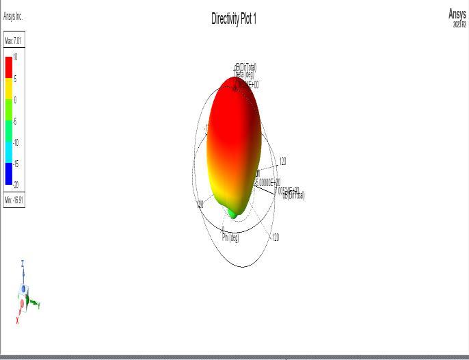
7.5DIRECTIVITYPLOT
Directivityshowconcentratedtheantenna'sradiationisina specificdirection.Higherdirectivitymeansthatmorepower is radiated in one direction, making the antenna more directional.
Units:DirectivityisgenerallymeasuredindBi.
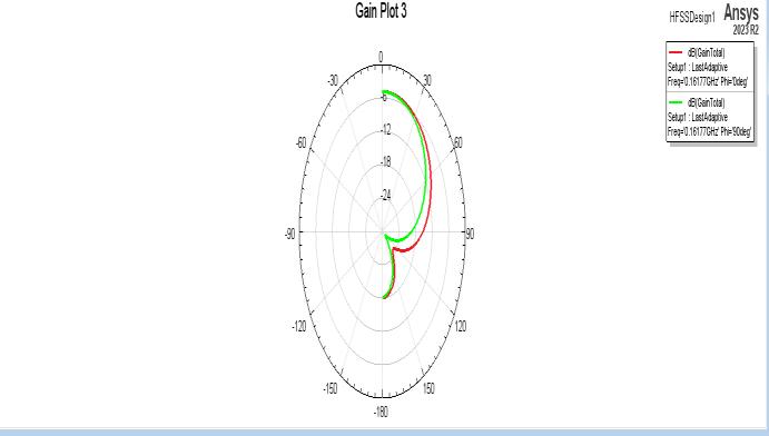
7.6GAIN
Gainisameasureofhowmuchpoweristransmittedinone direction versus an isotropic antenna (which radiates equallyinalldirections).GainoftenisstatedasdBi.
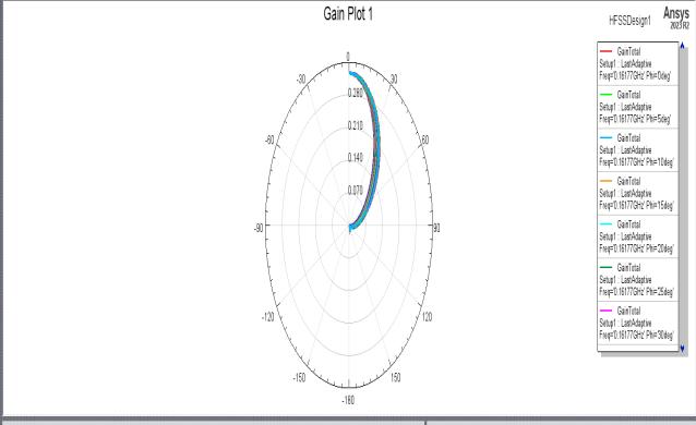
Fig-9 Gain
7.7E-FIELDANDH-FIELDRADIATIONPATTERNOFTHE ANTENNA
E-field(ElectricalField)RadiationPattern:
Thisfiguredepictsthedistributionofelectricfieldstrength surroundingtheantenna.Itshowshowtheelectrical field radiates from the antenna, which is important for understanding polarization and radiation properties. A shadeofredindicatesanelectricalfieldinspecificdirection.
H-field(magneticfield)RadiationPattern:
This figure displays the distribution of magnetic field strength around the antenna. It complements the E-field patternandiscriticaltounderstandingtheantenna'soverall radiation properties. The shade of green represents a magneticfield.
Thedesignandsimulationofarectangularmicrostrippatch antenna tailored to VHF marine communication offer promising results for upgrading maritime communication systems. The return loss of -20.1860 dB shows a good impedance match between the antenna and the feed line, reducing reflected power and ensuring efficient transmission.AVSWRof1.21isclosetotheidealvalueof one,suggestingthattheantennaisproperlymatchedtothe transmission line, resulting in little signal loss and great efficiency. The antenna's impedance matching, radiation pattern,andgainatVHFfrequenciesareoptimizedthrough careful selection of substrate materials, patch design, and feedmechanisms,allowingforreliablecommunicationover longdistances.
International Research Journal of Engineering and Technology (IRJET) e-ISSN: 2395-0056
[1] F.S.Alqurashi,A.Trichili,N.Saeed,B.S.OoiandM.S.Alouini,"MaritimeCommunications:ASurveyonEnabling Technologies, Opportunities, and Challenges," in IEEE Internet of Things Journal,vol.10,no.4,pp.3525-3547,15 Feb.15,2023,doi:10.1109/JIOT.2022.3219674.
[2] W. An, H. Wang, J. Wang, Y. Luo, K. Ma and J. Ma, "Low-ProfileWidebandMicrostripAntennaIntegratedWith Solar Cells," in IEEE Transactions on Antennas and Propagation,vol.70,no.9,pp.8530-8535,Sept.2022,doi: 10.1109/TAP.2022.3188647.
[3] L. Xing et al., "A High-Efficiency Wideband Frequency-Reconfigurable Water Antenna With a Liquid Control System: Usage for VHF and UHF Applications," in IEEE Antennas and Propagation Magazine,vol.63,no.1,pp. 61-70,Feb.2021,doi:10.1109/MAP.2019.2946556.
[4] M.PehlivanandK.Yegin,"X-BandLow-Probability Intercept Marine Radar Antenna Design With Improved Bandwidth and High Isolation," in IEEE Transactions on Antennas and Propagation, vol. 69, no. 12, pp. 8949-8954, Dec.2021,doi:10.1109/TAP.2021.3096952.
[5] W. Kim et al., "Ferrite-Loaded, Low-Profile GroundedBowtie-LoopAntennaforVHFCommunication," in IEEE Antennas and Wireless Propagation Letters,vol.22, no. 12, pp. 3132-3136, Dec. 2023, doi: 10.1109/LAWP.2023.3311965.
[6] I.G.A.K.DiafariD.H.,I.MadeOkaWidyantara,D.M. Wiharta,P.ArdanaandN.Pramaita,"DesignandSimulation of Log Periodic Dipole Array Antenna for 162 MHz AIS receiver," 2021 International Conference on Smart-Green Technology inElectricalandInformationSystems(ICSGTEIS), Sanur, Bali, Indonesia, 2021, pp. 136-141, doi: 10.1109/ICSGTEIS53426.2021.9650382
[7] H. Jia and P. X. . -L. Feng, "Very High-Frequency Silicon Carbide Microdisk Resonators With Multimode Responses in Water for Particle Sensing," in Journal of Microelectromechanical Systems,vol.28,no.6,pp.941-953, Dec.2019,doi:10.1109/JMEMS.2019.2920329.
[8] GozalNurRamaditya andYulisdinMukhlis,"Design AndManufacturedOfLpdaAntennaAt400Mhz-800Mhz FrequencyAndItsImplementationOnTelevisionAntenna", JEEMECS,vol.2,no.2,pp.25-29,August2019.
[9] Y. -H. Qian and Q. -X. Chu, "A Broadband Hybrid Monopole-Dielectric Resonator Water Antenna," in IEEE Antennas and Wireless Propagation Letters,vol.16,pp.360363,2017,doi:10.1109/LAWP.2016.2577049.
[10] H. Liang, M. Yao and Q. Zhu, "Design of a fractal antenna for marine rescue," 2016 IEEE International Symposium on Antennas and Propagation (APSURSI), Fajardo, PR, USA, 2016, pp. 275-276, doi: 10.1109/APS.2016.7695846.
[11] C.Hua,Z.ShenandJ.Lu,"High-EfficiencySea-Water MonopoleAntennaforMaritimeWirelessCommunications," in IEEE Transactions on Antennas and Propagation,vol.62, no. 12, pp. 5968-5973, Dec. 2014, doi: 10.1109/TAP.2014.2360210.
[12] F. Bass, I. Fuks, A. Kalmykov, I. Ostrovsky and A. Rosenberg,"Veryhighfrequencyradiowavescatteringbya disturbed sea surface Part I: Scattering from a slightly disturbedboundary,"in IEEE Transactions on Antennas and Propagation, vol. 16, no. 5, pp. 554-559, September 1968, doi:10.1109/TAP.1968.1139243.
[13] M. L. Parkinson, "Observations of the broadening andcoherenceofMF/lowerHFsurface-radaroceanechoes," in IEEEJournalofOceanicEngineering,vol.22,no.2,pp.347363,April1997,doi:10.1109/48.585954.
[14] A.Scorzolini,V.DePerini,E.Razzano,G.Colavolpe, S.Mendes,P.Fiori,etal.,"Europeanenhancedspace-based AISsystemstudy", 2010 5th Advanced Satellite Multimedia Systems Conference and the 11th Signal Processing for Space Communications Workshop,pp.9-16,2010.
[15] P. Last, M. Hering-Bertram and L. Linsen, "How automaticidentificationsystem(AIS)antennasetupaffects AISsignalquality", Ocean.Eng.,vol.100,pp.83-89,2015.
[16] Vijay S. Kale and Dnyandev B. Patil, "Software Development and Construction of Log Periodic Dipole AntennaUsingMATLAB", InternationalJournalOfInnovative Research In Electrical Electronics Instrumentation And Control Engineering, vol. 3, no. 12, pp. 83-87, December 2015.
[17] Z. M. Abdullahi and K Ahmad, "Design And SimulationOfHighGainLogPeriodicDipoleArrayAntenna", BayeroJournalOfEngineeringAndTechnology(Bjet),vol.13, no.2,pp.28-36,August2018.
[18] Glen Dash, "Designing Log Periodic Antennas", GlenDash at alum.mit.edu Copyright 2000 2005 Ampyx LLC.
[19] C.ABalanis,AntennaTheoryAnalysisAndDesign, NewJersey:JohnWiley&Sons.,2005.
[20] Y.Kosta,"Liquidantenna", IEEEAP-SInt.Symp.Dig., vol.3,pp.2392-2395,2004-Jun.
Volume: 11 Issue: 08 | Aug 2024 www.irjet.net p-ISSN: 2395-0072 © 2024, IRJET | Impact Factor value: 8.315 | ISO 9001:2008
| Page490
International Research Journal of Engineering and Technology (IRJET) e-ISSN: 2395-0056
Volume: 11 Issue: 08 | Aug 2024 www.irjet.net p-ISSN: 2395-0072
[21] H. Fayad and P. Record, "Wideband saline-water antenna", Proc. Inst. Electr. Eng. Wideband and Multi-band Antennas and Arrays Conf.,pp.197-201,2005.
[22] H.FayadandP.Record,"Broadbandliquidantenna", Electron. Lett.,vol.42,no.3,pp.133-134,2006.
[23] E.Paraschakis,H.FayadandP.Record,"Ionicliquid antenna", Proc. IEEE Int. Workshop Antenna Tech.: Small Antennas and Novel Metamaterials,pp.552554,2005.