
International Research Journal of Engineering and Technology (IRJET) e-ISSN: 2395-0056
Volume: 11 Issue: 08 | Aug 2024 www.irjet.net p-ISSN: 2395-0072

International Research Journal of Engineering and Technology (IRJET) e-ISSN: 2395-0056
Volume: 11 Issue: 08 | Aug 2024 www.irjet.net p-ISSN: 2395-0072
Akshai A S1
1Department of Mechanical Engineering, College of Engineering Trivandrum, Kerala, India ***
Abstract – In case Formula Student vehicle, where the design and manufacturing are primarily done by students, safety is given top priority. Impact Attenuator (IA) is one such structure, which is attached to the front bulkhead of vehicleto absorb the impact energy during the time of collision which ensures that the driver would be safe. Impact attenuator comes with several material and designs to absorb maximum energy with low level of deceleration. In case of material selection, aluminum is widely used to make IA, other material like impaxx 700 foam is also used to make light weight solid block impact attenuator. Safety of impact attenuator is validated by several criteria mentioned in FSAE rules. When aluminum is used for impact attenuators, the honeycomb structure is commonly employed because of its lightweight nature and exceptional energy absorption property due to its unique pattern. But there may be a chance that some other patterns could perform well than honeycomb and could employed in Impact attenuator. This paper focuses on FEA analysis of different type grid pattern and its effectiveness in energy absorption. The simulation is performed using LSDYNA software which is widely used in crash simulation
Key Words: impact attenuator, honeycomb, plastic deformation,formulastudent
1.INTRODUCTION
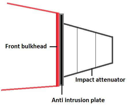
Inautomotivesector,ensuringsafetyduringhighimpact collision is a major concern. This is likely to occur in competitionslikeFormulaStudent(FS).ImpactAttenuatoris onesuchdevicewhichisengineeredtoabsorbenergyduring impactbyundergoingplasticdeformation,therebyreducing theforcetransmittedtodriver,ensuringhissafetyaswellas preventingdamagetovehiclecomponents.IAispositioned on front bulkhead, which is attached along with antiintrusion plate (Fig.1). Selection of material and design of impact attenuator must be done by engineering through specificrequirementssuchasabsorbingmaximumenergy, limiting peak deceleration experienced by the driver. The testconditionasper[1]isinsuchawaythatIAshouldbe mounted ona300kgvehicleandimpactinga nonyielding impact barrier with an impact speed of 7m/s. The deceleration shouldnotbeexceeding20gaverageand40g peakandtheenergyabsorbedinthisconditionmustmeetor exceed7350J.Foreaseofaccessanduse,mostteamsprefer to use impact attenuator made of foam material mainly impaxx700foam.Energyabsorptionandlightweightness
are key requirements for energy absorbing pads in industries [3]. Albak et al. [2] conducted the study on standard IA foam.[4] conducted the study on crashworthinessofpolyurethanefoamforimpactattenuator usingFEAmethod.
IA is one such device which can be modified in wide variety of ways to improve performance. Laksmana Widi Prasetyaetal.[5]designedcrashworthyIAmadefromwaste aluminium can based material. The experiment was conductedinbothexperimentalandFEAmethodandfound that cans with specific thickness and with proper arrangements can be used to make IA. [6] implemented a shoulderpatterninIAandstudieditseffectsinantiintrusion plate. This is mainly conducted to avoid peak deceleration.[14], [15] studied the effect of composite materialstobeusedasimpactattenuator.Attenuatorsalso comewithseveralshapes.Forstandardimpactattenuator,it willbetruncatedpyramidwithrectangularbase,someforms ellipticalshapewithgridsinsideit.MostcommonIAwhich usesaluminium hasseveral boxstructureattachedone to other.Eachdesignsprovidesitsownsignificanceduringthe crash.Whenitcomestomaterialselection,apartfromfoam
International Research Journal of Engineering and Technology (IRJET) e-ISSN: 2395-0056
Volume: 11 Issue: 08 | Aug 2024 www.irjet.net p-ISSN: 2395-0072
andcompositetypes,aluminiumisoneofthewidelyused material for impact attenuator. Use is mainly due two factors- property of excellent energy absorption through plasticdeformationandlightweightness.Thehighstrength toweightratioalsoenablestoreducetheoverallloadinthe vehiclewhichisessentiallyfocusedbytheteams.
Honeycombstructureis theprimestructuretypemade fromaluminiumwhichisusedtomakeIA.Inseveralstudies, honeycomb structure has proved to be excellent energy absorber.[7]conductedexperimentswithlowestmassand highest energy absorption combination. Due to unique pattern of honeycomb, overall mass of attenuator can be reduced without compromising the material. [8] made IA withsandwiched panel and aluminium innersheets along withhoneycombstructureforeachunitsandanalysedthe effect of dynamic loading in it. Qiang Chen et al.[9] the modifiedstructureofhoneycombandhowitfunctionsbetter than conventional one by studying uniaxial compression. The hexagonal structure results in collapsing through buckling or folding of cell wall during deformation. The patternisalsomadetodeformthestructurecontinuously without concentrating the stress to particular point. The compression occurring during impact also absorb energy anddistributethestresstoattachedcells.[10]showshow thedeformationofcellinorigamimodelcouldinfluencethe energyabsorptioncharacteristics.
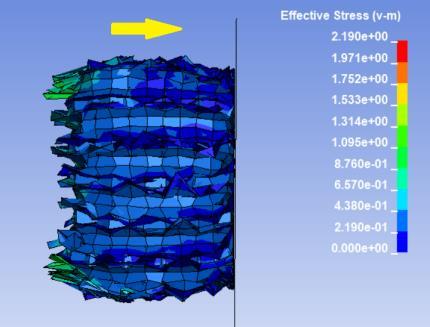
Eventhough grid pattern with honeycomb structure gained wide popularity due to several experiments and positive test data, there may be chance that some other structuresmayperform more effectivelythanhoneycomb structure.Thispaperfocusonenergyanddecelerationstudy three different grid pattern for impact attenuatorhoneycombgrid,squaregridandtriangulargrid.Thestudy also aims to find the best pattern structure to be implementedinIA. Duetomeshinglimitationsandextended runningtimes,theimpactattenuatoranalysisdoesnotdone bychoosingthebaselineconditionsfordimensions,energy absorption,anddecelerationasspecifiedintheFSrulebook [1].Instead,allthreestructuresaresimulatedunderuniform of conditions that are more manageable and simplify the simulationprocess.EntiresimulationisperformedusingLS DYNA(Fig.2).
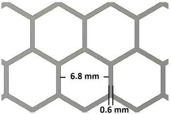
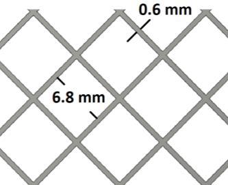
Thematerialmodelselectedwasaluminiumalloy6061T6 known for its high energy absorption capability. The materialiswidelyusedinaerospaceandautomotivesector. Fordifferentgridpattern,thematerialwith0.6mmthickness isselectedwhichindicatesthematerialspacebetweentwo cellsinthestructure.Thebaselinedimensionforhoneycomb cellwasselectedas6.8mm(Fig.3).Suchsmalldimensionin cell structure helps to integrate more material which can absorb energy to deform plastically and at the same time
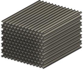
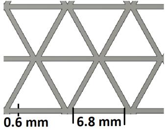
maintainingstructuralrigidity.Incaseofsquarecells,each sideistakenas6.8mm, spacedequallyat0.6mmthickness toformfinalstructure(Fig.4) Intriangularcells,equilateral triangle is considered where length of each side is 6.8mm (Fig.5).
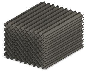
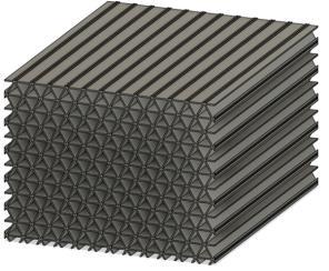
Theoverall dimension of thestructureisconsidered as 100mmx75mmx125mm,itisimportanttonotethatthisis not standard dimension as referred in the FS rule book. Dimension is reduced to this value by maintaining aspect ratio with original one inorder to reduce the simulation complexity and time. Since the study is a comparison between different structures, the above mentioned dimensionperformswellinsimulation.Thesolidmodelwas designed in Fusion 360 software and then downloaded in igesformattoimporttoLSDYNA.
Gridmodelisdrawninfusion360andextrudedtoform particular solid shape. The model obtained is exported in iges format and uploaded to LS DYNA. Solid meshing is
International Research Journal of Engineering and Technology (IRJET) e-ISSN: 2395-0056
Volume: 11 Issue: 08 | Aug 2024 www.irjet.net p-ISSN: 2395-0072
providedtothemodelwithanelementsizeof11alongwith layeroption,whichisessentialtoenablewhensimulating materials having thickness that needs to be accurately represented. From the front end of the IA to a distance of 50mm, a rectangular shell was modelled using “Shell 4N” from shape mesher option. The shell was modelled to represent the rigid wall on which the IA will impact to achievethesimulationresult.Themeshwasdoneinsucha way that 10 vertical and 10 horizontal lines divides the rectangleintosmallersquaresections.
Thencomesthecrucialpartofmaterialselectionforboth IAandrigidwall.Incaseofrigidwall,itwon'tbeaconcern becausethematerialuseddoesnotinfluencealotsincethe wallisassumedtobestationeryandwillbeconstrainedin alldirection.Butgivinginputofexactmaterialpropertiesto IA wascrucial part.Itisimportanttodefinecurvesection basedonstressstraingraph[12]for6061T6.Definingcurve enables software to understand the material’s nonlinear behaviourandaccurateresponsetoloadingcondition.Since theabsorptionofenergytakesplaceinplasticregion,curve definition is very important. Under material definition section, the material category assigned to model was “MAT_024_PIECEWISE_LINEAR_PLASTICITY”,amodelthat can predict material behaviour for a wide range of deformation including elastic and plastic region. Since aluminium is an elastoplastic material, this material propertyisthebestsuitsforit.Incaseofrigidwall,material propertywasassignedassteel.Thethicknessofrigidwall wasmadeas1mm.
Defining boundary condition is important to study the impact result. The movement of IA was restricted in all directionexceptinXaxis.Incaseofrigidwall,themovement is restricted in all direction. Constraining rigid wall in all direction is necessary to give baseline for simulating all threestructures.Totalmassof300kgisattachedtorearside ofIAtoensurethatthebodyhavesufficientmomentumand have enough energy during the time of collision.
“AUTOMATICSURFACETOSURFACECONTACT”wasdefined to detect contact surfaces and their interactions which resultsinaccurateanalysis.Thevelocityinxdirectionwas definedas15m/swhichwillexertsufficientenergyduring collision.
Thesimulationisperformedforanendtimeof15seconds andtworesultsareplottedwhichisnecessarytocompare theperformanceofstructures.
(i)InternalEnergyvstime
(ii)Acceleration
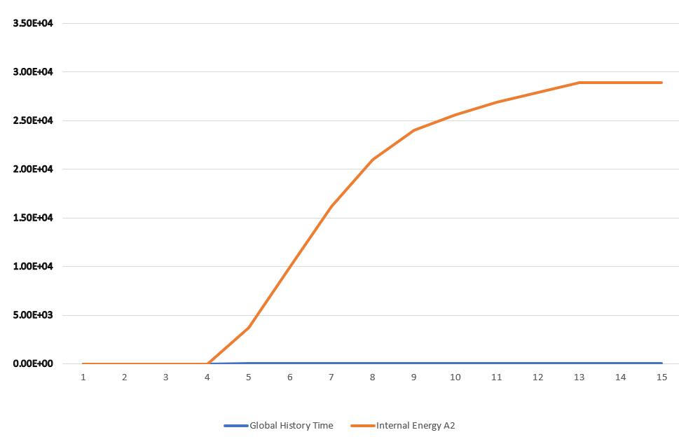
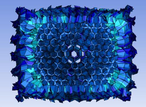
Incaseofhoneycombstructure,theenergyabsorptionis foundtobemaximumwithavalueofwithavalueof36742J (Fig.6). The pattern of honeycomb structure allows it to deforminspecificmannerallowingefficientdistributionof
force between cellular structure. More deformation by bucklingoccursintheperipheralregionthanincentralpart (Fig.12). When the impact force first applied on grid structure, the walls of hexagonal cells experiences compression.Thecontrolledcollapsingensuresthatenergy is absorbed uniformly which is clearly depicted in the constant slope of internal energy vs time graph. The deceleration value obtained is 422 m/s² (Fig.7) which is lowestascomparedtodecelerationofotherstructures.

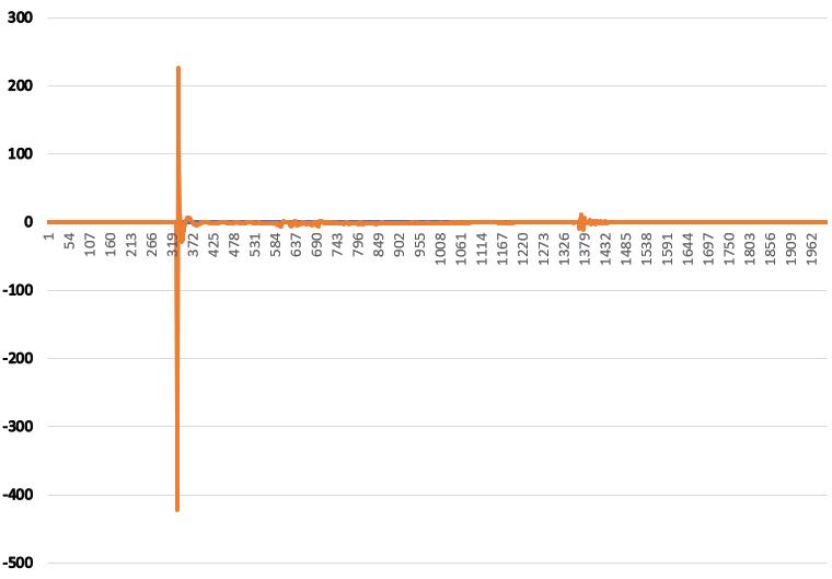
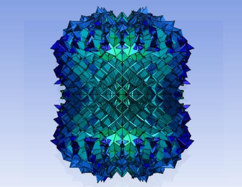
Square grid pattern comes in the second position for absorbingenergy,themaximumenergyabsorbedis28956J (Fig.8).Theresultobtainedhasasignificantdifferencefrom that of honeycomb structure. The deceleration value obtained is 497 m/s²(Fig.9). In case of square grid, it undergoes plastic deformation by elongation of square structure to parallelogram or trapezoidal shape (Fig 13) Comparedtohoneycombgeometry,thedeformationismore insquarepatternbuttheenergyabsorptionisless.
International Research Journal of Engineering and Technology (IRJET) e-ISSN: 2395-0056
Volume: 11 Issue: 08 | Aug 2024 www.irjet.net p-ISSN: 2395-0072
-8:InternalenergyvsTimegraphofsquaremodel
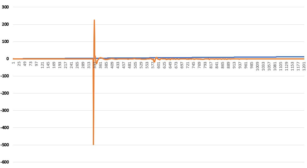
Fig -9:Accelerationgraphofsquaremodel
Triangulargridpatternhasleastenergyabsorptionand highestdecelerationvalue,clearlyindicatingthatitcannot be used for the purpose of impact attenuator. The energy absorbed is very low with value of 15122 J(Fig.10) and deceleration remains very high with value of 537 m/s². A highdecelerationvalueisnotdesirableasacharacteristicof theimpactattenuator.
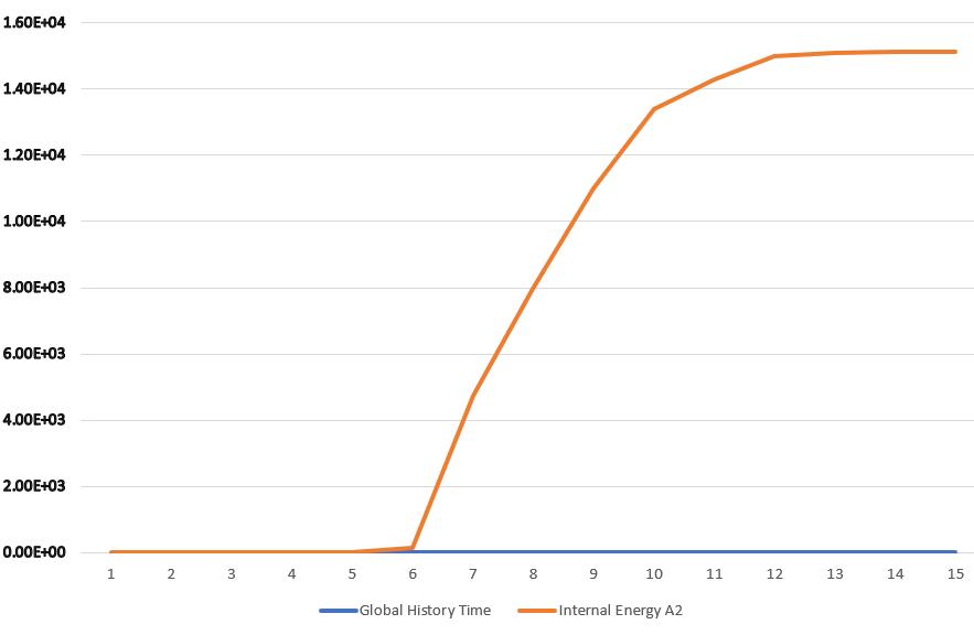
-10:Internalenergyvstimeoftriangularmodel
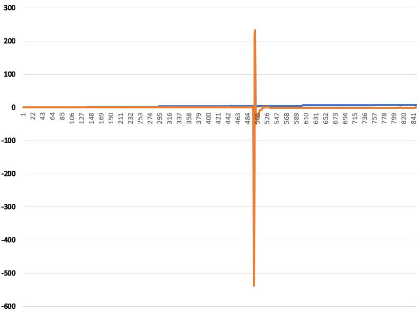
:Accelerationgraphoftriangularmodel
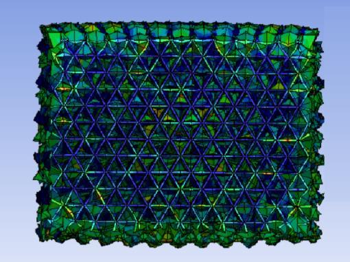
Triangle is the strongest and stiff shape which makes the entire structure more rigid and less vulnerable to deformationunderimpact(Fig14).Duetotheconstrainof triangularshape,insteadofsignificantplasticdeformation, thestructureundergoesfracture.
International Research Journal of Engineering and Technology (IRJET) e-ISSN: 2395-0056
Volume: 11 Issue: 08 | Aug 2024 www.irjet.net p-ISSN: 2395-0072
5.CONCLUSION
Theresultsobtainedfromanalysisalignswithfindingsof otherresearchersconfirmingthathoneycombstructuresare most suitable for impact attenuator. It owns the highest energyabsorptionvaluewithlowestvalueofdeceleration which is crucial for crashworthy impact attenuators. Honeycombstructureeffectivelydistributeimpactforceand undergoplasticdeformationwithoutconcentratingstressto localisedregion,allowinggreaterabsorptionofenergywith minimal deceleration. While square patternsabsorbsome amount of energy, they won’t match with capability of honeycombpattern.Ontheotherhand,triangulargeometry behavesdifferently.Duetostabilityoftriangularstructure, they resist plastic deformation, leading to low resilience value which indicates that energy from impact is not absorbedeffectively.Thefindingssupporttheeffectiveness of honeycomb structures over other patterns and will be useful for guiding future research and development in improvingthedesignsofimpactattenuatorforFSvehicles.
6.REFERENCES
[1] Formula Student rules 2023: https://www.formulastudent.de/fileadmin/user_upload /all/2023/rules/FS-Rules_2023_v1.0.pdf
[2] E. İ. Albak, E. Solmaz, N. Kaya, and F. Öztürk, “LIGHTWEIGHTFOAMIMPACTATTENUATORDESIGN FOR FORMULA SAE CAR,” Turkish Journal of Engineering, vol. 2, no. 1, pp. 17–21, Jan. 2018, doi: https://doi.org/10.31127/tuje.330658
[3] M. Yıldızhan et al., “Design of improved energy absorbing pads to reduce occupant injuries in vehicle sideimpact,” International Journal of Vehicle Design,vol. 71, no. 1/2/3/4, p. 174, 2016, doi: https://doi.org/10.1504/ijvd.2016.078775.
[4] A. Shaaban and A. M. Elsabbagh, “Crashworthiness Optimization of Impact Attenuators Constructed of PolyurethaneFoam,” InternationalJournalofAutomotive Technology,vol.23,no.2,pp.389–401,Apr.2022,doi: https://doi.org/10.1007/s12239-022-0036-8
[5] L.W.Prasetya,A.R.Prabowo,U.Ubaidillah,I.Istanto, andN.A.B.Nordin,“Designofcrashworthyattenuator structures as a part of vehicle safety against impact: Application of waste aluminum can-based material,” Theoretical and Applied Mechanics Letters,vol.11,no.2, p. 100235, Feb. 2021, doi: https://doi.org/10.1016/j.taml.2021.100235
[6] P. M. Quoc et al., “On Aluminum Honeycomb Impact AttenuatorDesignsforFormulaStudentCompetitions,” Symmetry, vol. 12, no. 10, p. 1647, Oct. 2020, doi: https://doi.org/10.3390/sym12101647.
[7] A.Vettorello,G.A.Campo,G.Goldoni,andM.Giacalone, “Numerical-ExperimentalCorrelationofDynamicTestof a Honeycomb Impact Attenuator for a Formula SAE Vehicle,” Metals, vol. 10, no. 5, p. 652, May 2020, doi: https://doi.org/10.3390/met10050652
[8] S.Boria,“BehaviourofanImpactAttenuatorforFormula SAECarunderDynamicLoading,” International Journal of Vehicle Structures and Systems,vol.2,no.2,May2010, doi:https://doi.org/10.4273/ijvss.2.2.01
[9] Q.Chen et al.,“Plasticcollapseofcylindricalshell-plate periodic honeycombs under uniaxial compression: experimental and numerical analyses,” International Journal of Mechanical Sciences,vol.111–112,pp.125–133, Jun. 2016, doi: https://doi.org/10.1016/j.ijmecsci.2016.03.020
[10] J. Qi, C. Li, Y. Tie, Y. Zheng, and Y. Duan, “Energy absorption characteristics of origami-inspired honeycomb sandwich structures under low-velocity impactloading,” Materials & Design,vol.207,p.109837, Sep. 2021, doi: https://doi.org/10.1016/j.matdes.2021.109837.
[11] N. Tanlak, F. O. Sonmez, and M. Senaltun, “Shape optimization of bumper beams under high-velocity impactloads,” Engineering Structures,vol.95,pp.49–60, Jul. 2015, doi: https://doi.org/10.1016/j.engstruct.2015.03.046
[12] L.D.R,K.G.J,andL.M.M,“ModelingLarge-Strain,HighRate Deformation in Metals,” Osti.gov, 2024. https://www.osti.gov/biblio/15005327(accessedAug. 26,2024).
[13] V.Shinde,“Editorial,” Ancient Asia,vol.3,Dec.2012,doi: https://doi.org/10.5334/aa.12301.
International Research Journal of Engineering and Technology (IRJET) e-ISSN: 2395-0056
Volume: 11 Issue: 08 | Aug 2024 www.irjet.net p-ISSN: 2395-0072
[14] S. Boria, J. Obradovic, and G. Belingardi, “On design optimization of a composite impact attenuator under dynamicaxialcrushing,” FME Transaction,vol.45,no.3, pp. 435–440, 2017, doi: https://doi.org/10.5937/fmet1703435b.
[15] J.Wang et al.,“Designandexperimentalverificationof composite impact attenuator for racing vehicles,” Composite Structures,vol.141,pp.39–49,May2016,doi: https://doi.org/10.1016/j.compstruct.2016.01.013.
© 2024, IRJET | Impact Factor value: 8.315 | ISO 9001:2008 Certified Journal | Page503