
International Research Journal of Engineering and Technology (IRJET) e-ISSN: 2395-0056
Volume: 11 Issue: 08 | Aug 2024 www.irjet.net p-ISSN: 2395-0072

International Research Journal of Engineering and Technology (IRJET) e-ISSN: 2395-0056
Volume: 11 Issue: 08 | Aug 2024 www.irjet.net p-ISSN: 2395-0072
Tejas Kumar S1,2,3 , Avinash Xavy2,3
1Head of New Product Development 2Metallurgist
3Vijay Spheroidals Pvt, Bangalore, India
Abstract – In the Centrifugal casting process, the molten metal is poured into vertical or horizontal molds which rotates at different speeds. This process causes (a) washing of dendritic or columnar structure formed at the mold metal interface and (b) separation of denser phases thrown towards peripheral region of the casting by centrifugal force. The lighter phases (like slag etc.) get separated and concentrated at the center of the casting from where it rises to the top of the casting (i.e., riser) zone.
This paper investigates the effectiveness of centrifugal force on the casting process in removing slag and other impurities in Spheroidals Graphite (SG) iron castings (IS 1865:1991) of size 120 x 120 x 500 mm. It also reports the changes in (a) optical microstructures and (b) mechanical properties of Spheroidal Graphite (SG) iron castings of size 120 x 120 x 500 mm.
Key Words: Vertical Centrifugal casting process, Spheroidals Graphite Iron, Microstructure, Centrifugal force, Slag, Dross
1.INTRODUCTION
FoundryIndustriesarealwaystargettoachieve(a)defectfreecastingsand(b)eliminatingimpuritiesformedduring melt treatment and casting process. In case of Spheroidal Graphite (SG) iron production, during magnesium (Mg) treatment,lotofslagandunwantedimpuritiesareproduced. Iftheyarenotremovedproperly,thecastcomponentwill failinserviceandcancausecataphoricfailure.Foundriesare extremely keen to adopt a green and commercially viable technologytocontrolsuchdefects
1.1
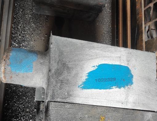
For the investigation, trials were conducted on EN GJS 450/10orIS1865SG450/10[withalloychemistryC:3.504.00, Si: 2.20-2.90, Mn: 0.3-0.6, P: 0.03-0.06, S: 0.02-0.040, Mg:0.020-0.060]materialusing250kgteapotspoutladleand verticalcentrifugalCasting(CC)machine.Sizeofcastingotsis 120mmx120mx500mm(plusriser)fromheatNo.1022-329 isshowninFig.1.AndfivemicrosamplesweretakenfromL2 (Fig2)thatisbelowthegatingregionfromheatNo.0823-07217,0823-18-557,0823-07-203,0823-09-265and0723-05-
149 respectively, to study the correlation between microstructureandmechanicalproperties,
International Research Journal of Engineering and Technology (IRJET) e-ISSN: 2395-0056
Volume: 11 Issue: 08 | Aug 2024 www.irjet.net p-ISSN: 2395-0072
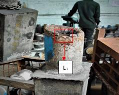
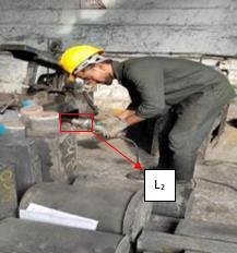
Fig.2andFig.3showsthepoints(L2 &L1)incastingots wheresamplesfor(a)opticalmicrostructure.Fig.2showsthe locationofsamplestakenfromfivealternatingheatsfor(a) optical microstructure and (b) mechanical properties has been collected to evaluate the effectiveness of the vertical centrifugalcastingprocesstoreduceslaginclusionsandto study the correlation between microstructure and mechanicalpropertiesrespectively,keepingmeltchemistry andotherparametersidentical,fivesampleswerecollected (shown in Fig 4) from five alternating heats. The data are comparedwithIS1865:1991andDINEN1563:2012-03SG ironcastingstodeterminetheeffectoftheverticalcentrifugal castingprocessonmicrostructuralpropertieswhichinturn affects the mechanical property of the component unavoidable.
2.1 Melting of alloy and microstructural analysis of samples collected from top of riser and bottom of the casting.
The experimental alloy composition is C: 3.50-4.00, Si: 2.20-2.90,Mn:0.3-0.6,P:0.03-0.06,S:0.02-0.040,Mg:0.020.06 which is as per with IS 1865:1991 SG 450/10 [equivalenttogradeDINEN1563:2012-03orEN-GJS-45010C] [9]. The charge materials melted in an air induction furnace.AftermeltingtheslagformerSLAX® isusedtoform theslagandtheslagisthenremoved.Themoltenmetalis
then tapped (at 1515oC) in the treatment ladle which is preheatedto650oCandthoroughlycleaned(fromslagand otherimpurities)beforepouring.AfterMgtreatmentinthe treatmentladle,themeltispouredintoahandshankwhere inoculationof0.40%and0.20%ofBismuthwithrespectto castingismaintained(asperprocesssheet)is giveninthe stream Aftertreatment,theslaggeneratedinthehandshank iscarefullyremovedbyaspoon.
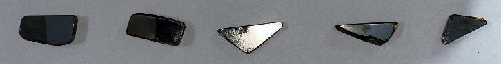
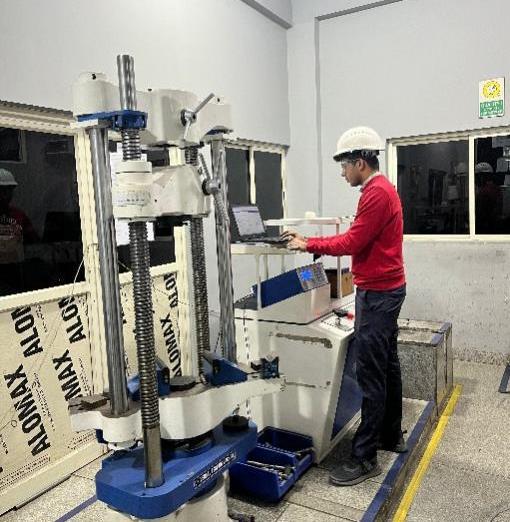
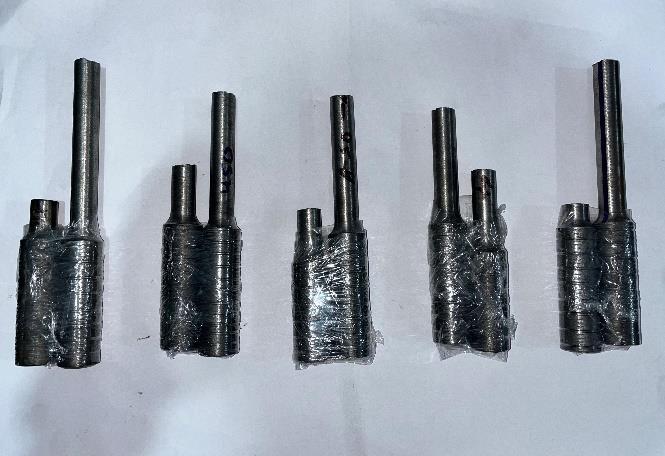
Themoltenmetalisthenpouredintoarotatingmoldwith sand thickness of 12.5mm for both casting mold and top gatingflange(whichactasrefractory)atlowerspeeds50100rpm(castingsize:120X120X500mm).Thepouring continuedtillmeltfills80%oftheriseranditensuredthe pouringiscompletedwithinfirst6minsafterinitialtapping. Graduallythespeedoftherotatingmoldisincreasedto130200rpm.Attheendoffreezing,thecastingsareknockedout at 451℃ and air cooled the casting to room temperature. Samplesformetallographicstudy(Fig.3andFig.2)aretaken from the top of riser (L1) and from the lower side of the casting (L2).Formicro-analysis, both unetchedand etched microsamples are studied using Dewinter Metallurgical microscope.ThefollowingresultsfromsamemicrosampleL1 aretabulated(inTable1)andcomparedwithASTMA247-19. Fig4showstheTensiletestingmachineandFig5showsthe brokensamplepiecesaftertesting
Table -1: ShowingNodularity,nodulecount,ferrite%and pearlite%fromsampleL1
2.2 Investigating the co-relation of microstructure and mechanical properties of five heats.
Fromtheselectedcomponentofsize120mmx120mx500 mmofalloycompositionC:3.50-4.00,Si:2.20-2.90,Mn:0.30.6,P:0.03-0.06,S:0.02-0.040,Mg:0.02-0.06whichisasper withIS1865:1991SG450/10[equivalenttogradeDINEN 1563:2012-03 or EN-GJS-450-10C] [9] maintained as per process parameter in above mentioned from varying heat Nos.of0823-07-217,0823-18-557,0823-07-203,0823-09265 and 0723-05-149 respectively. Five test bars are machinedasperIS1865:1991fromsameheatnoofsame grade.Alltheprocessparametersarekeptaspertheprocess sheet of SG 450/10. And it is specifically ensured that the componentsforthecasestudyarefreefromfoundrydefects
TheExperimentalapparatusincludesacentrifugalmachine,a componentofsize120x120x500mmfromwhichthetest
International Research Journal of Engineering and Technology (IRJET) e-ISSN: 2395-0056
Volume: 11 Issue: 08 | Aug 2024 www.irjet.net p-ISSN: 2395-0072
barismachinedfromthebottomofthecomponent.Thetest bar along with heat no, is tested in the universal testing machinefortensileproperty.Theresultsarecomparedwith IS 1865 and DIN EN 1563, the consolidated results are compared with microstructural analysis of samples from their respective heat no. Fig 5 Shows the tensile testing machine and Fig 6 shows the broken sample pieces after testing.
3. RESULTS AND DISCUSSIONS
3.1 Comparison study of microstructural analysis of sample from top gating and near gating system
As per ASTM A247-19, the sample taken from top riser L1 which shows an average nodularity of 37.20%(Table -1), whichislowerthantherequiredvalueasperIS1865:1999-
SG450/10orENGJS450/10.Theetchedmicro-imageofthe samplefromriserareaL1 (Fig-7)showsexcessivepearlitic matrix,withoutanyadditionofpearliticpromoterssuchas CuorMn.Thisisduetofasterrateofheatextractionthrough metallicmoldwillnothappenassandthicknessof12.5mmis presentatthetopgatingwhichactasrefractory.Fig-7also showsthepresenceofslagskinwhichisentrappeddueto fast cooling of the sample. This slag is Mg-Ca-silicate is formedafterMgtreatmentfollowedbyinoculation.Theslag density(2.5to3.5g/cc)isverylesscomparedtothedensity SGiron(6.9to7.8g/cc).So,duringrotationinCCmachine, thelighterslagisaccumulatedattheperipheralregionofthe castingandthenfloatsuptotheriser.Thus,itisseparated fromthebasemetalandyieldsgoodcasting.
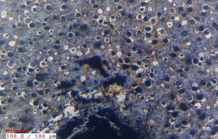
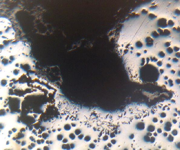
Fig-7andFig-8,showsthemicroimageofdross,whichis formed when the inoculation is not mixed properly. As a result,thenoduleswillnotbeformedinsteadsmallerflaker will be formed. These micro defects can be only observed underamicroscope.DrossisMg-Ca-silicatewhichisformed duringthecastingprocess,duringreoxidationofMgrejected by the cast metal precede to its solidification [4]. Table -2 gives the consolidated Nodularity, nodule count, ferrite %
International Research Journal of Engineering and Technology (IRJET) e-ISSN: 2395-0056
Volume: 11 Issue: 08 | Aug 2024 www.irjet.net p-ISSN: 2395-0072
andpearlite%fromsampleL1.Manymicro-defectswerealso observed in the sample. The average value from different regionsofthesampleshowthatL1sampleisnotasperASTM A247-19.
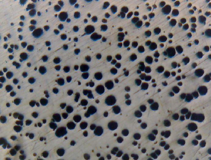
Fig -9:unetchedmicro-imageofasamplefrombelow gatingareaL2 at100x
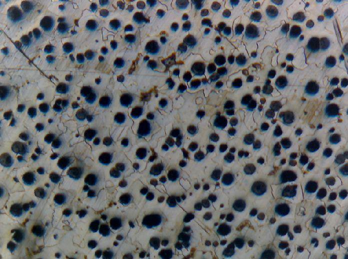
Fig -10:Etchedmicro-imageofasamplefrombelow gatingareaL2 at100x
Fig-9andFig-10,showstheunetchedmicro-imageofthe samplefromthelowersideofgatingregionofthecasting,L2 Itshows(a)averagenodularitywas96.57%,(b)nodulecount 364/mm2 and(c)freefromanymicro-defects.Theimageis matching with ASTM A247-19 with Type I and Type II graphite.Fig-10showsthemicroimageofetchedsampleL2 containingferrite–94.84%andpearlite-5.15%phases(table -2).
Table -2: ShowingNodularity,nodulecount,ferrite%and pearlite%fromsampleL2
3.2Co-relation between microstructuralproperties and mechanical properties of centrifugal cast test bars.
Table-3andTable-4showsresultsofmetallographic andmechanicaltestingoffivesamplesfromdifferent heats.
Table -3: ShowingNodularity,nodulecount,ferrite%and pearlite%ofdifferentheatswithcorrespondingheatno.
Table -4: Showingnodulecountandmechanicalstrength ofcorrespondingheatNoofSG450/10.
International Research Journal of Engineering and Technology (IRJET) e-ISSN: 2395-0056
Volume: 11 Issue: 08 | Aug 2024 www.irjet.net p-ISSN: 2395-0072
BasedontheMicroanalysisoffivedifferentheatnoand correspondingtensilestrengthagraphisplotted.(Chart1).
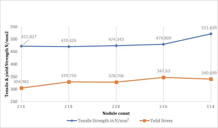
Chart -1:Depictstherelationbetweenthenodulecount, tensilestrengthandYieldStrength.
Micro-samplesweretakenfromthegatingregionaswellas belowthegatingregionforanalysis,andthefollowingpoints wereinterpreted:
1. During micro-analysis there was the presence of pearlite in the sample even though pearlitic promoters weren’t added during melting stages, thisshowsthatthegatingregionhasalargenumber ofimpuritiesandslag.
2. Pearlitehasincreasedinthegatingregionbecause impurities such as Mg-Ca-silicate, and SiO2 have risentotheriserregion.
3. Allofthedefectsfoundinthegatingregionandthe micro-imageofthesamplesfrombelowthegating region are devoid of the defects due to the centrifugal force and their differences in specific gravity.
4. Generally higher section thickness of 120 x 120 x 500mm, there is a possibility of defects such as graphite floatation and chunky graphite, which is not observed in the trial, as per EN-GJS-450-10C, withrelevantwallthickness30mm<t≤60mmand 60mm<t≤300mmasatensilestrength,elongation andYieldStressof440N/mm2,8%and300N/mm2 respectively,castingmechanicalintheblockwere observed450–472N/mm2
Micro samples of five different heats were analysed and resultswerecomparedtotheirmechanicalpropertiesfrom observationsfollowingpointscanbeinterpreted:
1. The edge microstructure image should be completelyferriticMicrostructure,aswemove toward the centre or core of the casting, we observeanincreaseinperlitecontent.
2. Anincreaseinnodulecountleadstoanincrease intensileandYieldStrengthaspertheTable-3 andTable-4.
3. Due to the centrifugal casting process heavy section casting gives higher nodule count and Nodularityevennearthecoreregionofcasting withoutchuckygraphiteorgraphitefloatation.
4. Thecentrifugalcastingprocessgivesastabilized increase in nodule count across various heats whichcanseenin5trialReports.
5. Thecentrifugalcastingprocessismoresuitable for producing high-section thickness symmetrical casting with better metallurgical properties.
The authors wish to express their deep gratitude to Vijay Spheroidals Pvt Ltd for their significant support and collaborationinthepreparationofthispublication,"Studyof Vertical Centrifugal Process of Nodular Graphite Iron throughtheCorrelation betweenMicrostructural Analysis and Tensile Property." The content of this article aligns closelywiththeexpertiseandoperationsoftheorganization, and their contributions were invaluable in ensuring the qualityandrelevanceofthestudy.
Disclaimer: Any similarity to content found on the Vijay Spheroidalswebsiteisintentional,asthesameauthorhas contributed to both this paper and the content on the website.
[1] P.G. Mukunda, Shailesh Rao A. & Shrikantha S. Rao (2009)InferenceofOptimalSpeedforSoundCentrifugal Casting of Tin, Canadian Metallurgical Quarterly, 48:2,157-165.
[2] N.Janco,“CentrifugalCasting”, American Foundry Men’s Society,1988.
[3] Supervisedlearningclassificationfordrosspredictionin ductile iron casting production - Scientific Figure on ResearchGate. Available from: https://www.researchgate.net/figure/Dross-defect-ina-ductile-iron-part_fig2_256194746
[4] Andersson,S.(2015). Study of Dross in Ductile Cast Iron Main Shafts [Thesis,Karlstadsuniversitet,Fakultetenför hälsa, natur- och teknikvetenskap (from 2013)].http://urn.kb.se/resolve?urn=urn:nbn:se:kau:di va-37148
[5] Gagné, M., Paquin, M. & Cabanne, P. (2008). Dross in ductileiron:source,formationandexplanation.InThe
International Research Journal of Engineering and Technology (IRJET) e-ISSN: 2395-0056
Volume: 11 Issue: 08 | Aug 2024 www.irjet.net p-ISSN: 2395-0072
68th World Foundry Congress, India, Chennai, 7-11 February2008,pp.101–106.
[6] IS1865(1991):Ironcastingswithspheroidalornodular graphite[MTD6:PigironandCastIron]
[7] ASTM A247-19: Standard Test Method for Evaluating theMicrostructureofGraphiteinIronCastings
[8] ASTM E2567-16a(2023): Standard Test Method for Determining Nodularity And Nodule Count In Ductile IronUsingImageAnalysis
[9] DIN1563:2012-03:SpheroidalGraphiteCastIrons.
[10] El-Banna,E.(1994,July).Astudyofferriticcentrifugally castductilecastiron. Materials Letters, 20(3–4),99–106. https://doi.org/10.1016/0167-577x(94)90069-8
BIOGRAPHIES


Tejas Kumar S, Metallurgist with 14 years of experience, currently working as Head of Design and Engineering at Vijay Spheroidals PvtLtd
AvinashXavy,Metallurgistwith3 years of experience at Vijay SpheroidalspvtLtd.
2024, IRJET | Impact Factor value: 8.315 |