
International Research Journal of Engineering and Technology (IRJET) e-ISSN: 2395-0056
Volume: 11 Issue: 08 | Aug 2024 www.irjet.net p-ISSN: 2395-0072

International Research Journal of Engineering and Technology (IRJET) e-ISSN: 2395-0056
Volume: 11 Issue: 08 | Aug 2024 www.irjet.net p-ISSN: 2395-0072
Prajwal V S1 , Dr. S G Srivani2
1Electrical and Electronics, RV College of Engineering, Bengaluru, India
2Electrical and Electronics, RV College of Engineering, Bengaluru, India
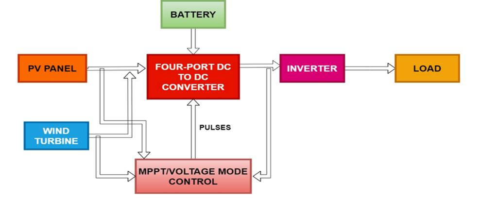
Abstract - A four-port DC-DC converter has been developed for integrating a hybrid energy from renewable sources system into an AC microgrid. This converter is particularly suitable for AC microgrid applications that require systemlevel power management. It boasts a straightforward design, making it effective forinterfacingsourceswithvaryingvoltage and current characteristics. The converter is created to connect a battery bank, a PV panel, a wind turbine, and an inverter, and a load. One of its key features is achieving zero voltage switching in steady-state conditions. To test its robustness, the converter is subjected to various scenarios simulating transient changes in the energy sources.Theentire system is modelled and tested using MATLAB/Simulink software and hardware implementation. Results from simulations and hardware that the converter can efficiently manage the process of filling and emptying the battery based on its state of charge. Additionally, it ensures that the DC-link voltage remains stable and maximum power from PV panel and Wind turbine is obtained by MPPT algorithm.
Key Words: four-port dc to dc converter, AC micro grid, Windturbine,PVpanel,battery,zerovoltageswitching.
1.INTRODUCTION
The world’s population is rapidly increasing, leading to greater energy demands. This growth, along with industrializationandurbanization,hassignificantlyboosted energy consumption [1]. Fossil fuels are scarce resources. Resources, not only face depletion but also contribute heavily to environmental issues such as air pollution and climatechange[2].Toaddresstheseproblemsandbecause of the limitations utilizing fossil fuels, the world's energy focusisshiftingtowardsrenewablealternatives[4].
Price fluctuations for petroleum and natural gas have decreasedtheallureofusingthesefossilfuelsasthemain source of energy, igniting interest in more reliable and sustainable alternatives. Due to its purity, environmental friendliness, renewability, and capacity to produce alternative energy, wind and solar energy have grown in popularity [5]. Distributed power generation is replacing massive centralized power generation as distributed renewable energy resources (RESs) such as photovoltaic (PV)arrays andwindturbinesareincreasinglyintegrated into the grid [3]. However, because renewable energy is
sporadic, batteries and additional energy-storing apparatuses are frequently utilized as a buffer against weather-relatedpowergenerationfluctuations[6].
Aviablemethodforplanninganddirectingtheapplicationof distributed energy resources(DER)isthedevelopment of microgrids.TherearevariousbenefitstolinkingDERstoa microgridprecedingthemaingrid.First,consideringsolar andwindpowermaycomplementeachother,usingdifferent sourcesofenergycanreducetheuncertaintyassociatedwith renewableenergysources[1].Second,comparedtoisolated energy from renewable sources systems, power managementinsidea microgridoffersa moredependable powergenerationprofile.
Powerconvertersarerequiredforcontrolthemicrogrid's power flow as well as the energy sources. They either provide the microgrid with inadequate power or absorb excess power produced by RESs [7]. Numerous energy sourcescanbeintegratedintothegridintwoprimaryways: either by utilizing numerous converters (one for each source)orbyemployinganintegratedconverter,alsocalled amultiportconverterwithinterfacecapabilityofmultiple sources. The latter approach is better since it does not require board-to-board interactions and provides a more compact structure and higher power density with shared componentsandcentralizedcontrol[8].
Themajorityofextantmultiportconvertersthatconnecta sourceofenergy,battery,andload(alsoknownasaDC-link) havethreeports.SeveralmultiportDC-DCconvertersmany architecturalstyleshavebeencreated,includinginterleaved buck-boost and boost topologies, dual active bridges, complete bridges, Z-source converters, three-phase structures,andLLCresonatingdesigns[9].However,these converterscannotlinktomorethanthreedifferentsources withoutaddinganadditionalport.Furthermore,mostthreeport converters are difficult to expand for four-port applications,withonlyafewfour-portarchitecturespossible without installing too many components. Furthermore, in mostreversiblethree-portconverters,onlythebatteryhasa reversible port, which can only be loaded by the RES [2]. Multiportconvertershandlediversesourcesofenergysuch as solar cells, wind turbines, and batteries, offering a compact,cost-effective,andhighlyefficientsolution[10].
International Research Journal of Engineering and Technology (IRJET) e-ISSN: 2395-0056
Volume: 11 Issue: 08 | Aug 2024 www.irjet.net p-ISSN: 2395-0072
Compared to three-port converters, there has been fewer studiesonfour-portbidirectionalconverters.Manystudies havefocusedondesigningfour-portbidirectionalconverters to link storage. However, in most existing four-port converters,thebidirectionalportwasspecificallydesigned forthebattery,meaningthebatterygetspowerthroughthe RES and fed to the DC link. This high-frequency charge/discharge cycle reduces battery life. The lack of a reversible port at the DC-Link prevents the energy in the microgridfrombeingstoredinthebattery,resultingina'use orwaste'issuewhenthemicrogridworksinislandmode.As a result, these four-port converters are appropriate for stand-aloneapplicationssuchassatellites,electricvehicles, solar battery systems, and hybrid sources of renewable energy systems [1]. To incorporate renewable energy sources into AC load applications, bidirectional power convertersareessential.Theyenableseamlessenergyflows inthetwodirections,whileMPPTensuresmaximumenergy capturefromPVandturbinesources[6].
The processof simulating a PV(photovoltaic)arrayand a windturbineincludedetermininghoweachwouldfunction under various operational and meteorological scenarios. Thisaidsinourcomprehensionoftheirenergyproduction capacity, efficiency, and the variables influencing their effectiveness. It is similar to forecasting how well wind turbinesandsolarpanelswouldperforminactualconditions so that we can make better plans for using renewable energy.
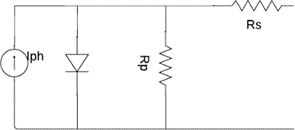
Tounderstandhowasolarcellworks,thinkofitasatypeof diode. When light, in the form of photons with the right energy,hitsthecell,itgeneratespairsofelectronsandholes. Theseelectronsandholesareseparatedbyanelectricfield
at the junction of the diode, and this separation creates a potential that drives the electrons and holes around an externalcircuit,generatingelectriccurrent.However,notall thecurrentgeneratedmakesittothecircuitduetolosses. These losses come from the cell's series resistance, which causes power loss as current flows through it, and shunt resistance,whichallowssomecurrenttoleakawayinstead ofgoingthroughthecircuit.Additionally,somecurrentleaks back across the p-n junction. These factors can be representedinanequivalentcircuitforthesolarcell,which includes a photocurrent source, a diode, series resistance, andshuntresistance.
International Research Journal of Engineering and Technology (IRJET) e-ISSN: 2395-0056
Volume: 11 Issue: 08 | Aug 2024 www.irjet.net p-ISSN: 2395-0072
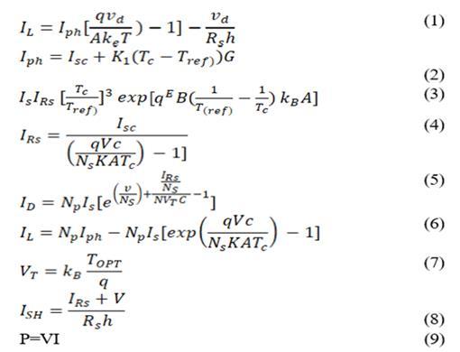
Renewable energy from wind is harnessed by a wind engine,whichconvertsitintomechanicalpower,andthena generator converts that mechanical power into electrical energy.Essentially,thekineticvitalityderivedfromtheair flowingthroughagivenareaistransformedintomechanical energy. The formula for the electricity generated by the windmillis:

ρrepresentstheairdensity,whichtypicallyrangesfrom 1.1 to 1.3 kg/m³.A is the area swept out by the turbine blades,measuredinsquaremeters(m²).Visthewindspeed, measured in meters per second (m/s).Pm is the wind power,measuredinwatts(W)orjoulespersecond(J/s).Cp isthepowercoefficient,thatisameasureofhowefficiently thewindenergyistransformedintomechanicalpower.This coefficientdependsaboutthepointofspeedratio(��)andthe pitchangle(��).
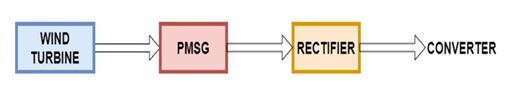
Theschematicblockstructureofagrid-connectedsystem fortransferringwindenergyusingPMSGisshownbelowfig 3.Itconsists ofthreemaincomponents:thewindturbine, PMSG, and a rectifier. The wind generator holds onto the kinetic vitality derived from the wind and converts it into rotational mechanical energy. Permanent Magnet SynchronousGenerator(PMSG)takesthemechanicalvitality derivedfromthewindengineandconvertsitintoelectrical power.Rectifier/ConverteristhecomponentchangestheAC outputfromthePMSGintoDCelectricity,whichisthenused toenergizedtheinverter.
3. WORKING AND OPERATION OF THE CONVERTER
Figure1illustratesatwo-stagegrid-connectedsystemthat integratesmultiple energysources. Thesourcesof energy arelinkedtoafour-portDC-DCconverter,wherePorts1and 2 are linked to a wind turbine generator (WTG) and a photovoltaic(PV)panel,respectively,andPort3islinkedto abattery.Theoutputfromthisfour-portDC-DCconverteris then fed into a DC-AC converter, which regulates the DC voltageandconvertsittoAC.InthisthePVpanelandwind turbineisprovidingpowerwhichisprovidedtotheloadand chargesthebattery.Theconverteroperatesinboostmode when the Power is generated derived from renewable resourceschargesthebatteryandprovidedtodcgrid.The P&OalgorithmisutilizedtomaximizePVpowerextraction panelandwindturbinesothatthepaneldirectlypowersthe
arrangementandwhentheirradiationreducesandthepanel powergenerationisreduced,thebatterystartsprovidingthe gridwiththecontrolistransferredtovoltagemodecontrol fromMPPT.WhenbothPVandWindturbineisunavailable, thenthebatterystartstodischargeandprovidessupplyto thegrid.Thismodeallowstheconvertertofunctioninbuck modeandchargesthebattery.WhenbatterySocisreduced belowthelimit,thebatterystartstochargeenergyderived fromrenewablesourcessuchasPVandWindturbinesource
3.1 The proposed converter is evaluated under the following conditions:
Event1:Whenenergyderivedfromrenewablesources,the DC-link(pDC)islessthan0,modeallowsthe converterto functionin buckmode,andthebatterychargesbyabsorbing energy derived from DC-link (Mode 1).When the energy generatedfromtherenewable(pRES)isgreaterthanzero, Modetwobecomesinmotion.
Event 2: When the electricity that is renewably generated (pRES)isgreaterthanthepowerrequiredthroughtheDClink(pDC),andpDCisgreaterthan0,thereisabundanceof green energy. The battery charges to absorb this excess energy,activatingmodestwoandthree.
Event 3: When power required through the DC link(pDC) exceedstheelectricitythatisrenewablygenerated(pRES), theelectricitythatisrenewableisinsufficienttopowerthe DC-link's load. The power source(battery) provides the additionalpowerneeded,activatingmodesfourandthree.
Event4:Whenthereisnorenewableenergyavailable(pRES = 0) and power required through the DC-link (pDC) is greaterthan0,theenergysource(battery)suppliesallpower totheDC-link,activatingonlyMode4.
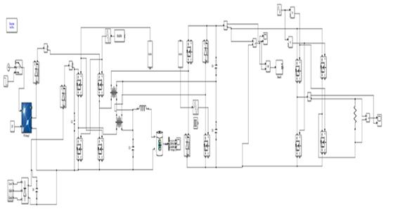
Fig-4 SimulationCircuitoftherecommendedfour portdc-dcconverterSystem
International Research Journal of Engineering and Technology (IRJET) e-ISSN: 2395-0056
Volume: 11 Issue: 08 | Aug 2024 www.irjet.net p-ISSN: 2395-0072
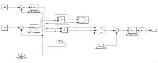
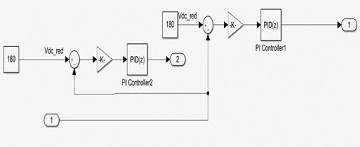
Inthis,thedutyratio(d)isgeneratedusingcurrentcontrol loopforwhichthereferencecurrentisgeneratedusingdc busvoltagecontrolloop.Thegenerateddutyratioisprovided to delay angle generation this is employed based on the availability of renewable sources and ac grid. The Perturb andObservealgorithmisemployedinformppttotakeout maximumpower
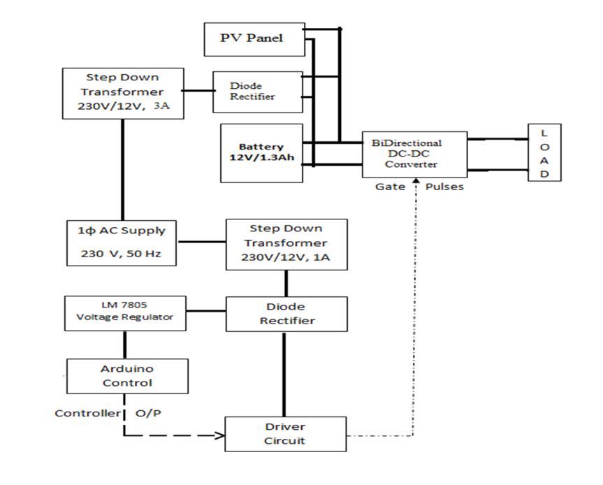
Inthisasingle-phaseACsupplyof230V,50Hzisprovidedto stepdowntransformerofvoltageratio230/12V,1A,50Hzso that it can be converted to DC voltage and regulated. The dioderectifierisusedtoconvertthe12Vacto12Vdcvoltage. Therectifieddc voltageisprovidedto5Vand12VVoltage regulator.The5VregulatedvoltageisprovidedtoArduino microcontrollerwhichgeneratesthepulsesaccordingtothe controlstrategy.The12Vregulateddcsupplyisprovidedto drivercircuitsothatitcanabletodrivethePowerElectronic switches of the proposed converter as per the gate pulses generatedfromthecontroller.
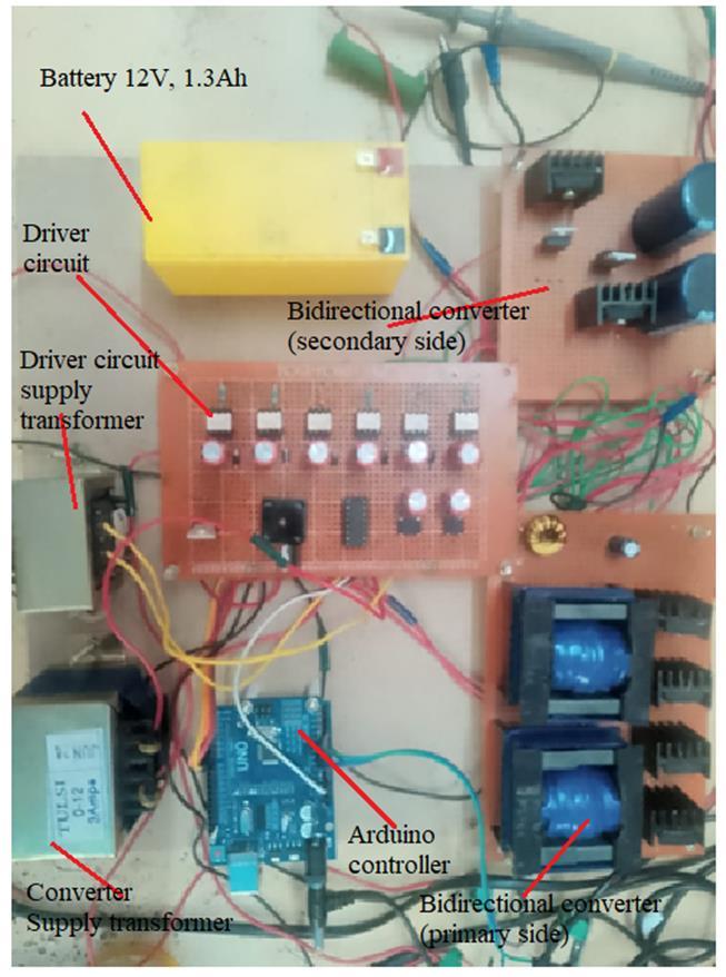
In this, 12V transformer voltage is subjected to diode rectifiertogetdcvoltagewhichisconnectedasasourceto theproposedconverterwhichwillboostthevoltageto48Vat loadside.A12V,1.3Ahbatteryisalsoconnectedwhichwill actasloadandgetschargedwhenprimarysupplyisavailable andstartstodischargewhentheprimarysupplyiscutoff.
ThepulsesfortheswitchesaregeneratedbytheArduino controller which will send the gate signal to the switches throughdrivercircuit.
The rectified voltage is provided to the Arduino and drivercircuitgetstheVccsupply.TheArduinogeneratesgate pulseforproposedconverterswitches.
International Research Journal of Engineering and Technology (IRJET) e-ISSN: 2395-0056
Volume: 11 Issue: 08 | Aug 2024 www.irjet.net p-ISSN: 2395-0072
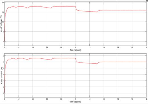
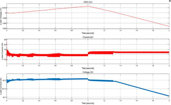
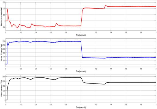
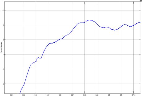
The above fig 4 shows the simulation circuit of the intended system. In this, the PV panel and Wind turbine source is connected to the system until t=1.5s and disconnectedat1.5s.ThePVprovidespowertotheloadfrom 0 s to 1s with 1000W/m2 irradiation and 400W/m2 from t=1sto1.5swhereitisdisconnected.Thebatterywasinitially charged with PV and as PV is disconnected at t=1.5s, the batterystartstodischargeandsuppliestheload.TheMPPT controlwillprovidepulsestotheconverterandthenasPVis disconnected,thestand-alonecontrolwillprovidepulsesto the converter from t=0.1.5s to 2s. The voltage with PV generatingpowerwithdifferentirradiationlevelsandwith batterycharginganddischargingmodes.Inthis,effectiveness of the converter with battery chargingcondition is 92.6%, andduringbatterydischargingmode,theeffectivenessofthe converteris93.2%fortheloadpowerof2KW.
International Research Journal of Engineering and Technology (IRJET) e-ISSN: 2395-0056
Volume: 11 Issue: 08 | Aug 2024 www.irjet.net p-ISSN: 2395-0072
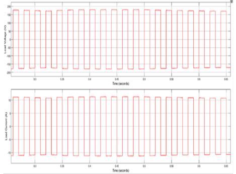
TheloadvoltageacrosstheRload
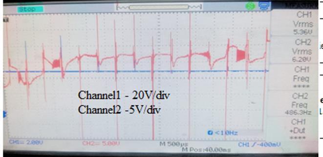
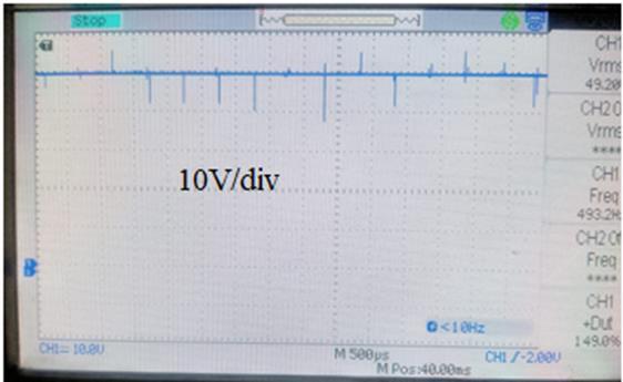
Fig-14 Theloadvoltagealongwithbatteryvoltagewhen batteryischarging
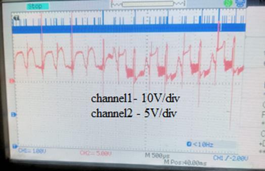
Fig-15 Theloadvoltagealongwithbatteryvoltagewhen batteryisdischarging
A brand-new DC-DC converter with four ports was developed for hybrid energy applications. This converter, based on a phase-shifting DC-DC converter, integrates variousenergysourcessuchasaphotovoltaic(PV)panel,a wind turbine generator (WTG), and a battery. This model helpedincreatingseveralcontrollerstomanagetheDC-link voltage,batteryvoltage,andcurrent.Simulationofconverter effectivelyexecutesMPPTforbothofPVpanelandtheWTG when solar and wind power are available. Additionally, it controlscharginganddischargingofbatteriestomaintaina steadyDC-linkvoltage
[1] Y.Sato,M.Uno,andH.Nagata,“non-isolatedmulti-port converterintegratingPWMandphase-shiftconverters,” IEEETrans.EnergyElectron.,vol.35,no.1,pp.455-470, Jan.2020.
[2] S. Venkataraman, C. Ziesler, P. Johnson, and S. Van Kempen, “Integrated wind, solar, and energy storage: Designing plants with a better generation profile and loweroverallcost,”IEEEPowerandEnergyMagazine, vol.16,no.3,pp.74-83,May-June2018.
[3] Bhattacharjee and I. Batarseh, “, A single-stage, threeport DC-DC-AC converter with sine PWM modulation, utilizing an interleaved boost and dual active bridge architecture,"IEEETrans.Ind.Electron.,vol.68,no.6, pp.4790-4800,June2021.
[4] J.Zhang,W.Jiang,T.Jiang,S.Shao,Y.Sun,B.Hu,J.Zhang, "AresonantDC/DCconverterfromthreeportLLC,"IEEE J.EmergingSel.TopicsenergyElectron.,vol.7,no.4,pp. 2513-2524,Dec.2019.
[5] J.Zeng,J.Ning,X.Du,T.Kim,Z.Yang,andV.Winstead,“A four-port DC-DC converter for a standalone wind and solarpowersystem,”IEEETrans.Ind.Appl.,vol.56,no. 1,pp.446-454,Jan./Feb.,2020.
[6] P.PrabhakaranandV.Agarwal,“Novelfour-portDC–DC converter for interfacing solar PV–fuel cell hybrid sourceswithlow-voltagebipolarDCmicrogrids,”IEEEJ. EmergingSel.TopicsPowerElectron.,vol.8,no.2,pp. 1330-1340,June2020.
[7] Q. Tian, G. Zhou, M. Leng, G. Xu and X. Fan, “A nonisolatedsymmetricbipolaroutputfour-portconverter interfacing PV-battery system,” IEEE Trans. Power Electron.,vol.35,no.11,pp.11731-11744,Nov.2020.
[8] T.ChaudhuryandD.Kastha,“AhighgainmultiportDC–DCconverterforincorporatingenergystoragedevices toDCmicrogrid,”IEEETrans.PowerElectron.,vol.35, no.10,pp.10501-10514,Oct.2020.
International Research Journal of Engineering and Technology (IRJET) e-ISSN: 2395-0056
Volume: 11 Issue: 08 | Aug 2024 www.irjet.net p-ISSN: 2395-0072
[9] P.Kolahian,H.Tarzamni,A.Nikafrooz,,“Multi-portDCDCconverterforbipolarmediumvoltageDCmicrogrid applications,” IET Power Electron., vol. 12, no. 7, pp. 1841-1849,June,2019.
[10] Y. Liang, H. Zhang, M. Du and K. Sun, “Parallel coordinationcontrolofmulti-portDC-DCconverterfor stand-alonephotovoltaic-energystoragesystems,”CPSS Trans. Power Electron. & Appl., vol. 5, no. 3, pp. 235241,Sept.2020.
2024, IRJET | Impact Factor value: 8.315 | ISO 9001:2008