
International Research Journal of Engineering and Technology (IRJET) e-ISSN: 2395-0056
Volume: 11 Issue: 09 | Sep 2024 www.irjet.net p-ISSN: 2395-0072


International Research Journal of Engineering and Technology (IRJET) e-ISSN: 2395-0056
Volume: 11 Issue: 09 | Sep 2024 www.irjet.net p-ISSN: 2395-0072
Nandita Gyanchandani1, Abhishek Govekar2, Parikshit Gokhale3 , Prof. Dr. Shrinivas Chippa4
1,2,3B.tech ,Mechanical Engineering, Vishwakarma Institute of Technology, Pune, Maharashtra, India
4Prof. (Dr)Shrinivas Chippa, Dept. of Mechanical Engineering, Vishwakarma Institute of Technology, Pune, Maharashtra, India ***
Abstract - Gears and gear drives have been fundamental components in various systems and machines for centuries. However, mastering gear design remains a complex skill. Continuous advancements in gear design have been driven by the ongoing demand for more cost-effective, quieter, lighter, and efficient machinery. An industrial gearbox facilitates the transfer of mechanical energy between devices, optimizing torque while reducing speed. By adjusting speed and torque, gearboxes convert energy into usable forms, contributing to smoother industrial operations. In this paper, a two-stage reduction gearbox with a total speed reduction ratio of 2.57 is presented.
Key Words: Gearbox, Speed Reduction, Two-stage, Industrial machinery, Power Transmission
1. INTRODUCTION
Areductiongearboxallowstheinputspeedtobelowered, resulting in a slower output speed while maintaining or enhancing the output torque. The reduction gear system comprises a set of rotating gears connected to an output shaft.High-speedinputfromthewheelworkistransmitted to these gears, where the speed and torque are modified. The number of gears required in the system depends on thespecificoutputspeedrequiredfortheapplication.This assembly is typically referred to as a reduction gearbox and can involve one or two stages, depending on the desiredoutputspeed.
Two-stage reduction gearboxes are commonly applied in situations involving high-speed operations. In this configuration, the pinion is attached to the input shaft via a key, and it is then connected to an intermediate gear, knownasthefirstreductiongear.Thisgeariscoupledtoa second low-speed pinion using an additional shaft, which is then linked to the second reduction gear mounted on theoutputshaft.
Theprimarycomponentsofthisgearboxincludethegears, shafts,bearings,casing,oil,andoilseals.
Gears are rotating, toothed components used to transmit power and motion between shafts by the engagement of
theirteeth.Gearsenableadjustmentsinspeed,torque,and direction of the power source. The teeth on interacting gears are identical in shape, and when multiple gears are arranged in a sequence, they form a gear train or transmission. By manipulating the gear ratio, gears typically provide a mechanical advantage through torque variation.
Thegearratio(i)representstherelationshipbetweenthe numberofteethonagearanditspinion.Itisgivenbythe equation: Where:
np =speedofpinion(rpm)
ng =speedofgear(rpm)
Zp =numberofteethonpinion
Zg =numberofteethongear
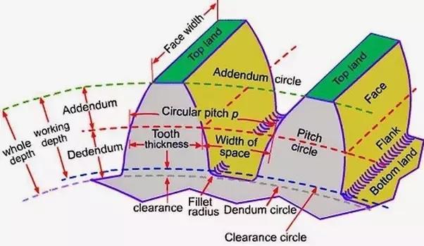
Source: Mechtics
Gearsaretypicallycategorizedintofourmajortypes:spur, helical, bevel, and worm gears. This project uses spur gears for a speed reduction ratio of 2.57 in an industrial gearbox.

Volume: 11 Issue: 09 | Sep 2024 www.irjet.net

In spur gears, the teeth are cut parallel to the axis of the shaft, making them suitable only when the shafts are parallel. The gear tooth profile follows an involute curve and remains consistent across the width of the gear. Spur gears apply radial loads to the shafts and are commonly foundindeviceslikewashingmachines,screwdrivers,and wind-upalarmclocks.However,theyareknownforbeing noisy due to the way the teeth engage, which also causes vibrations. For this reason, spur gears are generally not used in applications like automobiles, where noise and vibrationcontrolarecritical.
The20°pressureanglesystemisusedbecauseofseveral benefits:
(a)Itreducesthelikelihoodofundercutting.
(b)Itminimizesinterference.
(c)Theincreasedpressureangleslightlybroadensthe toothbase,enhancingitsstrengthandloadcapacity.
(d)Itoffersalongercontactlengthbetweenteeth.
A shaft is a rotating component responsible for transmitting power from one part to another. The power is transferred by a tangential force, and the resulting torque helps deliver energy to other machines connected to the shaft. Shafts are typically stepped, with a larger diameterinthemiddleandsmallerdiametersatbothends where bearings are placed. These steps create shoulders to hold transmission elements like gears, pulleys, and bearings in position. The rounded portion between sections of different diameters is called a fillet, and it is designedtoreducestressconcentrationscausedbyabrupt changes in the shaft's cross-section. Components are mounted onto the shaft using keys or splines. Effect of stress- concentration due to abrupt change in the crosssection. The various members are mounted on the shaft usingkeysorsplines.
-0072
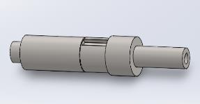
Shafts are subjected to axial tensile forces, bending moments, torsional moments, or a combination of these forces. Typically, shafts endure combined bending and torsional stresses, and shaft design involves selecting the appropriatediametertoensurestrengthandrigidity.
A bearing is a mechanical component that facilitates relative motion between two parts with minimal friction. Its key functions include ensuring smooth shaft or axle rotation, supporting and holding the shaft or axle in position,andtransferringforcesactingontheshafttothe frameorfoundation.
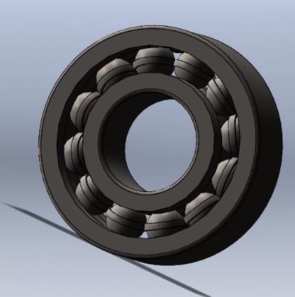
A rolling contact bearing is composed of four main parts: theinnerandouterraces,arollingelement(suchasaball, roller, or needle), and a cage that holds the rolling elements in place and evenly distributes them around the shaft's periphery. Bearings are categorized based on the type of rolling element used, including ball bearings, cylindrical roller bearings, taper roller bearings, and needle bearings. Additionally, bearings are classified by theloaddirectiontheyhandle,eitherasradialbearingsor thrustbearings

-0056
Volume: 11 Issue: 09 | Sep 2024 www.irjet.net p-ISSN: 2395-0072
ApplicationsofRollingContactBearings: Rolling contact bearings are commonly used in the followingareas:
1. Spindlesofmachinetools
2. Frontandrearaxlesofautomobiles
3. Gearboxes
4. Smallelectricmotors
5. Ropesheaves,cranehooks,andhoistingdrums
The casing serves as a structural enclosure that holds the shafts in place and houses all the gears, ensuring they function together without interference. It also features mounting pointsforinstallationina powertrainassembly and absorbs the load imposed by the power source. If an engine powers the system, the casing also transmits vibrations. To prevent failure, the casing design includes intricatecontours.
Bearingsocketsareintegratedintothecasing,allowingfor the installation of bearings, which then accommodate the shafts.Thecasingalsohasaninletforaddinggearoil,and it should be airtight to maintain the cooling efficiency of the oil. Typically, gearbox casings are designed as a twopiece,symmetricalstructuretofacilitateeasyopeningand closing during maintenance. High precision in casing manufacturing is crucial to avoid misalignment issues. Cast iron has long been the preferred material for producingcasings.

1.5 Oil and Oil seals
Gear oil is a lubricant specially designed for use in transmissions, transfer cases, and differentials in various machines, including vehicles. It has a high viscosity and oftencontainsorganosulfur compounds.Oil sealsserve to preventcontaminantslikedirtfrom enteringand keep oil or grease from escaping. A typical oil seal consists of a rigid outer metal ring and a flexible inner sealing component, chemically bonded to the metal ring for durability.
Thedesignofgearsprimarilydependsonthemoduleand the number of teeth. While the module must be the same forgearsinmesh,thenumberofteethcanvarytoachieve speedreductionorincrease.Thefirststepingeardesignis determining the number of teeth on each gear. Standard gear systems, based on the pressure angle, provide guidelinesforthis.Forthisproject,a20°pressureangleis used. According to this standard, a minimum of 18 teeth on the pinion is required to avoid undercutting and interference,whichiswhythisvalueischosen.
The motor’s input angular speed (Np) is 1440 rpm, and the output angular speed (Ng) is 560 rpm. Thus, the total speedreductionratio(i)is:
i = 1440 / 560 = 2.57
This gearbox design includes two stages, meaning the speed reduction occurs in two phases. The gear ratio at eachstageisequal,giventhatthenumberofteethonboth pinionsandgearsineachstageisthesame.Thegearratio at each stage is the geometric mean of the total reduction ratio.
Thus,gearratioateachstage,i.e., i’ is,
i ‘= (i) 1 / 2
i ‘= (2.57) 1 / 2
i ‘= 1.603
Forpinion,
Numberofteeth,Zp = 18
Forgear,
Zg / Zp = i
Zg = i x Zp
Zg = 29
Atfirststage,
Ng /Np = Zp / Zg
Np = 1440, Zp = 18, Zg = 29
Ng = 893.79 = 900 rpm

Volume: 11 Issue: 09 | Sep 2024 www.irjet.net p-ISSN: 2395-0072
Atsecondstage,
Ng /Np = Zp / Zg
Np = 900, Zp = 18, Zg = 29
Ng = 560 rpm
At the second stage, the rotational speed is lower, but sincethetotalpowerisdeterminedbytorque,theangular velocity (W) must remain constant. This leads to an increase in torque at the second stage compared to the first. As a result, the second stage becomes more critical thanthefirst,makingitthefocusoftheanalysis.
The service factor (Cs) is selected as 1.25, based on the system's configuration, which involves a uniform driving machine (electric motor) and a medium shock driven machine(maindriveformachinetools).
Sincethepitchlinevelocityisnotknownatthispoint,the velocity factor (Cv) cannot be determined directly. However, assuming a pitch line velocity of 5 m/s, the velocityfactoriscalculatedas:
Cv = (3 / 3 + V) = (3 / 3 + 5) = 3 / 8
For calculation of module(m) based on bending strength wehavethefollowingformula,
Asweareusingthesamematerialforpinionandgear,the pinionwillbeweakerastheLewisformfactorYislower forthepinion.
Now,
(power)kW=5kW
Cs=1.25
Fs=1.5
Zp=18
N=900rpm
Cv=3/8
B/m=10mm
Sut=750N/mm2
Y=0.308
After putting all these values in the equation, we get modulemas,m=3.38=4mm
Gear Dimensions,
m=4mm
dp=mxZp=4x18=72
dg=mxZg=4x29=116
b=10, m =40mm
Calculation of Bending Strength:
Forcalculatingthebendingforceexertedonthepinion tooth,wehavethefollowingformula,
Here,
m=4mm, b=40mm, ��=750/3N/mm2,Y=0.308
Aftersubstitutingthesevaluesintheequation,weget, Sb = 12320 N
Calculation of wear strength:
Forcalculationofwearstrength,wehavethefollowing formula,
Here, b =40mm, Q =2XZg/(Zg+Zp)=1.234, dp =72
K =0.16(BHN/100)2(ForEN31Steel)=1.85
Thus, Sw = 6574.752 N
Now,Sb=12320NandSw=6574.752N
Itisclearthat Sw < Sb, Thus,furtheranalysismustbedone basedonSw.

International Research Journal of Engineering and Technology (IRJET) e-ISSN: 2395-0056
Calculation of dynamic load and thus effective load using Buckingham equation:
Forcalculatingmomentexertedongeartooth,wehavethe formula,
Here,kW=5kW,n=900rpm
Thus, Mt = 53051.65 N-mm
Here, Mt = 53051.65 N – mm, dp = 72
Thus, Pt = 1473.66 N
Fordynamicload,assuminggrade4typeofgears,
e=3.2+0.25xΦ
Where,Φ=m+0.25x(d) ½
Thus,ep=4.73,eg=4.87
Now,e=ep+eg
Thus,e=9.60µm
Now, pitch line velocity, V is calculated as,
d=72mm,n=900rpm
Thus, V = 3.39 m / s
Dynamic load by Buckingham equation is given by,
Thus,
Here, V=3.39m/s
C=11400
E=9.60µm
Pt =1473.66N
Pd = 2820.64 N
Now, Peff = Cs x Pt + Pd
Here,
Pt=1473.66N
Pd =2820.64N
Cs =1.25
Thus, Peff = 4662.71 N
Now, Sw = 6574.752 N &Peff = 4662.71 N
Here, Fos = Sw / Peff = 1.41
This indicates that the design meets the required standards, confirming that the chosen module is appropriate for this application. Therefore, using this module,theremaininggeardimensionswillbecalculated.
Final Dimensions:
1) Module: 4 mm
2) Face width: 40 mm
3) Addendum: 4 mm
4) Dedendum: 5 mm
5) Clearance: 1.5 mm
6) Working depth: 8 mm
7) Whole depth: 8.628 mm
8) Tooth thickness: 6.2832 mm
2.2 Shafts
Input Shaft:
Inputtorque=power/ω=
=33.15N
MT=33.15Nm.
MT =Ftx(Dp/2)
[Dpisthepitchcirclediameterofpinion=72mm]
Ft=2x(MT/Dp)
Ft=920
F=Ft/cos(20)=979.765N (20=Pressureangle)
Volume: 11 Issue: 09 | Sep 2024 www.irjet.net p-ISSN: 2395-0072 © 2024, IRJET | Impact Factor value: 8.315 | ISO 9001:2008 Certified

International Research Journal of Engineering and Technology (IRJET) e-ISSN: 2395-0056
Volume: 11 Issue: 09 | Sep 2024 www.irjet.net p-ISSN: 2395-0072
Fr=Ft*tan(20)=334.85N

Fig-6: Loads on input shaft
Source: Madeusinghttps://app.diagrams.net/
forXYplane
TakingmomentatptA;
RBY x220=frx130
RBY =197.86N.
TakingmomentatptB
RAY x 220=fr x 90
RAY =136.98N.
BendingmomentintheX-Yplane
170<x<150
RAY ×15- Fr x20=20547Nmm forXZplane:
TakingmomentaboutA;
RBY X220= Ft x130
RBZ=552.5N
RAZ =935 - 552.5= 382.5N
BendingmomentinX-Zplane;
170<x<150
RAZ ×15 - Ft x20=57375Nmm
Resultantbendingmoment:
MB=√(205471²+(57375)² = 60943.168Nmm
For fully reversed loading: and √ and
Von-Mises Criteria:
DE Goodman’s Equation:
SF=safetyfactor;itisrecommendedas2commonly,
SCF=stressconcentrationfactor;itisrecommendedas3,
Sn=endurancestrength;itequals280MpaforC45steel inaccordancewithEN10083-2standard
Sy=yieldstrength;itequals370MpaforC45steelin accordancewithEN-10083-2standard.MBandTinarethe sameascalculatedearlier.
D=23.74mm
Similarly,D=24mmforIntermediateshaftandD=26.38 mmforoutputshaft
2.3 Keys
Accordingtointernationalstandardsforsquarekey,
b=h=d/4=28/4=7mm
l=1.5*d=1.5*28=42mm
whereb=h=sideofsquare l=lengthofkey d=diameterofshaft
© 2024, IRJET | Impact Factor value: 8.315 | ISO 9001:2008 Certified Journal | Page816

International
Volume: 11 Issue: 09 | Sep 2024 www.irjet.net p-ISSN: 2395-0072
Forgear,
Pitchcirclediameter=
d’=mxz=4x29=116mm
Addendumcirclediameter= da=m*(z+2)=4X31=124mm
Dedendumcirclediameter= df=m*(z-2.5)=4*26.5=106mm
Shaftdiameter=d=28mm
Facewidth=b=40mm
So,forblankconstruction:
d1=outerdiameterofhub=1.5xd=42mm
tr=thicknessofrim=2xm=8mm
b1=thicknessofweb=0.25xb=0.25x40=10mm
d3=innerdiameterofrim=df-2tr=106-16=90mm
d4=diameterofholesinrim=(d3-d1)/4=12mm
d2=PCDofholes=(d1+d3)/2 =66mm
forpinion,
Pitchcirclediameter=d’=mxz=4x18=72mm
Addendumcirclediameter=da=mx(z+2)=4x20 =80mm
Dedendumcirclediameter=df=mx(z-2.5)=4x15.5= 62mm
Shaftdiameter=d=28mm
Facewidth=b=40mm
Soforblankconstruction:
d1=outerdiameterofhub=1.5x d=42mm
tr=thicknessofrim=2xm=8mm
b1=thicknessofweb=0.25xb=0.25x40=10mm
d3=innerdiameterofrim=df-2tr=62-16=46mm
2.5 Bearing Selection
ID=17mm
Fr=maxstaticload=1178N
Forindustrialgearbox
L10h=15000hours
L10=60xn x L10h/10^6=504millionrevolutions
Asthereisnoaxialload,
P=Fr
C=px(L10)^(1/3)=1178x(504)^(1/3)=9375
Frommanufacturer’scatalogue:
d=17mm
D=40mm
B=12mm
Designationforbearingis6202.
L=Overalllengthofgearbox(inmm)
L=310
Wallthicknessofhousing:
t1=(0.012xL)+5
t1=8.72mm
Wallthicknessofcovering:
t2=0.8to1timest1
t2=8.72mm
Wallthicknessofmatingflanges:
t3=1.5xt1
t3=13.08mm(eachflangeis13.08mmthick)
Wallthicknessofhousing:
t4=2xt1
t4=17.44mm
Thicknessofribs:
t5=0.85xt1
t5=7.41mm
a=Centredist.betweeninputandoutputshafts
a=94mm
Diameteroffoundationbolts:
df =(0.036xa)+12
df =15.384mm
Diameterofbearingbolts:
ds =0.75xdf
ds =11.538mm
Diameterofboltssecuringhousingandcovering:
ds =0.6xdf
ds =9.23mm
Diameterofboltsofbearingcaps:
db =0.5xdf
db =7.692mm

International Research Journal of Engineering and Technology (IRJET)
-0056
Volume: 11 Issue: 09 | Sep 2024 www.irjet.net p-ISSN: 2395-0072
Distanceoffoundationboltaxisfromhousingwall:
dw =(1.25xdf)+5
dw =24.23mm
Distanceofboltaxissecuringcoveringandhousingfrom housingwall:
dw =(1.2xds)+5
dw =16.076mm
Widthoffoundationflange=dw +df +5 =44.614mm
Widthofflangeconnectinghousingandcovering=1.2ds + df +5=31.46mm
2.6 Oil and Oil Seal:
Pitchlinevelocity=3.39m/s
Temp.ingearbox=maximumis60℃
So,fromthetable,ISOVG220oilisrequired.
Amountofoilrequired:
Toothdepth(h)=9mm
Oillevelmustbebetween-hto3h
So,accordingtomodelandotherdimensions,
Volume=(Lengthofhousing)x(breadthofhousing)x (heightofhousing-radiusof gear+2h)
Volume=(315)x(180)x[72-58+(2x9)]
Volume=1814400mm3
Volume=1.8Litres
So,approximately1.8Litresofgearoilisrequiredfor smoothfunctioningofthisgearbox.
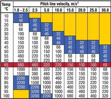
fig-7:Selection of oil
Source:https://www.machinerylubrication.com/Read/92 6/gear-oils
Oil Seal - MaterialisNBRRubberastemperatureisbelow 100℃.
Dimensionsare-outerdiameterofshaftxborediameterx width=16x40x10
So,#1333SizedOilSealisselected.
3.
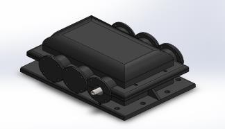

4. Bill of Materials
Bill of Materials

Volume: 11 Issue: 09 | Sep 2024 www.irjet.net p-ISSN: 2395-0072
Agearboxcanfunctionaseitherareduceroranincreaser, depending on the specific requirements of the machine. Staged gearboxes are developed to enhance system compactness and efficiency, with two-stage gearboxes being the most used in industrial applications. These gearboxesconsistoffourgearsandthreeshafts.Research shows that for two-stage gearboxes, the most efficient configuration involves using identical pinions and gears, meaning that the gear ratio for each stage should be the same. Gears can be designed by performing precise calculationsbasedonthesystem'srequirements.Thegear blank is crafted to withstand stress while minimizing mass,achievedbyaddingwebsatstrategiclocations.Shaft designmustconsiderassemblyneeds,leadingtotheuseof stepped shafts designed with factors such as gear weight, applied torque, and radial force in mind. Keys are used to secure the gear to the shaft, and bearings are selected to minimize friction during shaft rotation, based on parameterssuchastotaldynamicloadandborediameter. The casing design is primarily determined by the centre distance between the two shafts. By considering all these factors,anoptimalgearboxcanbedesigned,ensuringboth requiredstrengthandminimalweight.
We express our sincere gratitude to Vishwakarma Institute of Technology (VIT) for offering us the opportunity and platform to develop this project. We wouldalsoliketoextendourheartfeltthankstoourguide, Prof. Dr. Shrinivas Chippa, for his invaluable support and guidancethroughoutthecourseofthisproject.
[1] Croccolo, D.; De Agostinis, M.; Vincenzi, N. Design and optimizationofshaft–hubhybridjointsforlightweight structures: Analytical definition of normalizing parameters.Int.J.Mech.Sci.2012,56,77–85.
[2] Croccolo, D.; Vincenzi, N. On the Design of Interference-Fitted and Adhesively Bonded Joints for LightweightStructures.J.Mech.Des.2011,133,1–8.R. Nicole, “Title of paper with only first word capitalized,”J.NameStand.Abbrev.,inpress.
[3] Hohn, B.R.; Michaelis, K.; Otto, H.-P. Minimised gear lubrication by a minimum oil/air flow rate. Wear 2009,266,461–467,doi:10.1016/j.wear.2008.04.037
[4] Conrado, E.; Gorla, C.; Davoli, P.; Boniardi, M. A comparison of bending fatigue strength of carburized and nitrided gears for industrial applications. Eng. Fail.Anal.2017,78,41–54.
[5] V.B. Bhandari; Design of Machine Elements 3rd Edition.
[6] GitinMMaitra;HandbookofGearDesign2ndEdition.


NanditaGyanchandani,(B.Techin MechanicalEngineering, VishwakarmaInstituteof Technology)


Abhishek Govekar, (B.Tech in Mechanical Engineering, Vishwakarma Institute of Technology)


Parikshit Gokhale, (B.Tech in Mechanical Engineering, Vishwakarma Institute of Technology)““


Professor (Dr) Shrinivas Chippa, Department of Mechanical Engineering,VIT,Pune.