
International Research Journal of Engineering and Technology (IRJET) e-ISSN:2395-0056
Volume: 11 Issue: 09 | Sep 2024 www.irjet.net p-ISSN:2395-0072


International Research Journal of Engineering and Technology (IRJET) e-ISSN:2395-0056
Volume: 11 Issue: 09 | Sep 2024 www.irjet.net p-ISSN:2395-0072
P. MADHU1 , Dr. E. ARUNAKANTHI2
1M.Tech student, JNTUA College of Engineering, Ananthapur, A.P., India
2Professor. JNTUA College of Engineering, Ananthapur, A.P., India
Abstract: Self-compacting concrete (SCC)isusedin placeswheretherecan be no accesstovibratorsfor compactionand in complexshapesofformwork,overaperiodoftimeconcretestructuremaycausecracks,spalling,andotherpotentialsignsof deterioration.In order toassesstheSCC structuresatinaccessiblelocationsthereis a needforthedevelopment ofreference chartsandbaselineimagesforconditionmonitoring.InthepresentstudyM20gradeconcreteiscastandcuredinwaterfor28 daysthenexposedtothechemicalsCH3COOH,NaCl,HCl,andH2SO4 forthedurationof7,14,28and56days. Thecolorprofiles of deteriorated surfaces are analysed in CIE-XYZ color pace, and the respective chromaticity diagrams are investigated. The chemicalexposedsurfacesarecapturedusingacamerathenprocessedinimageprocessingsoftwaretoquantifythechangein surfacecolorsontheconcreteandhistoryofdeterioration.Duetothechemicalattack,thereisaphysicalchangeinconcrete.A correlationisestablishedbetweenphysicalchangesandvisionchangesontheconcretesurfacethenthecorrelationgraphsare dawn by the compressive strength and x and y values. This approach contributes to the sustainability of SCC structures for enablingproactivemaintenancestrategies.
Key words: compaction, formwork, cracks, image processing, deteriorated surfaces, chemical attack, compressive strength, CIE-XYZcolorspace.
Globally,concreteisacommonlyutilisedbuildingmaterial, and as technology has advanced, so too have its qualities. To improve the many characteristics of concrete, a variety of varieties have been created. There are four phases to this development thus far. Traditionally, concrete with normal strength is the oldest and consists of just four ingredients: cement, water, medium and coarse particles. One of the greatest advancements in modern construction technology worldwide is Self-Compacting Concrete (SCC). One of the biggest advancements in the building business recently is "high performance concrete," which is also known as "self-consolidating concrete." Using home garbage, industrial byproducts, and other treated and untreated resources as raw materials for concrete is a contemporary global trend. They contribute to a cleaner, greenerenvironmentinadditiontofacilitatingthereuseof materials. The purpose of this study is to investigate the feasibility of utilising waste materials to prepare creative concrete.
The technique of manipulating a picture to improve it or extract valuable information is called image processing. It involves the manipulation of images to achieve a desired outcome, such as improving visual quality, correcting distortions, or identifying specific features. In The current
investigation M20 grade concrete gets exposed to toxic chemicalsafterithasbeencastundtreatedusingwaterfor 28days.CH₃COOH,NaCl,HCl,andH2SO4 forthedurationof 7,14,28,and56days.
Aftercuringtheconcretemoldsthenattackonacidstothe concretetomixtheacidsonwaterbyevery1literofwater addon5%ofacidstobeadded,afteraddingonchemicals attacking at certain room temperature and lighting also providedthenaftercuringiscompletetochecktheweight, diagonaldimension,andcolor. aftertocapturetheimages on concrete molds to convert the photos into color pigmentation
Healthmonitoringofself-compactingconcrete(SCC)using image processing is a modern and efficient approach to assessing the structural integrity and detecting deterioration in concrete structures. This technique leveragesadvancedcomputervisionandmachinelearning technologies to provide non-destructive evaluation, enabling early detection of issues and ensuring the longevityandsafetyofSCCstructures.
Prasannaetal.,2016(1)thisistostudythecrackdetection many studies utilize technigues like canny edge detection

International Research Journal of Engineering and Technology (IRJET) e-ISSN:2395-0056
Volume: 11 Issue: 09 | Sep 2024 www.irjet.net p-ISSN:2395-0072
or sobel filtering to identify cracks in concrete surfaces. Canny edge detection is widely used for detecting discontinuities or changes in pixel intensity to highlight cracks or surface deformations . Using colorimetry research, Guru Prathap Reddy and colleagues (2022) conducted a recent study on a unique method for assessing concrete deterioration. in this paper I am using chromaticity method and chemicals used for HCl, H2SO4, NaCl. In this method to quantify the colors of concrete deteriorated surfaces by damaged surfaces when the color profiles are identified by the deteriorated surfaces are analyzed by CIE-XYZ color space and the respective chromaticity diagrams are investigated. In this case to study the image-based identification of damage, analytical, objective assessment of the degree of deterioration, and analysis of the relationship between the degree of deterioration and concrete strength. feng et al 2017 (3) this is to study the changes in the surface texture can indicate concrete deterioration, studies explore using wavelet transforms for detecting surface anomalies such as scaling or delamination in concrete, these technique are particularly useful for identifying early stage degradation, allowing for protective maintenance. 3D reconstruction advanced image processing integrates photogrammetry and 3D modeling to detect concrete volume changes, providing a clearer understanding of structural deformation or spalling. Komac ˇka et al., 2019 (4) It is crucial to standardise the quality of photos captured for digital image processing, whichmeansmanagingthecameraandcomprehending the impact of lighting. By means of histogram analysis, thesecharacteristicsimpactthedifferentiationbetween bitumen and aggregate. M K Gokay et al (5) this research explores the impact of chemical exposure on the colour properties of concrete, employing imagebased analysis within the CIE-XYZ colour space. The results demonstrate the chemical exposure leads to significantchangesinchromaticityofconcretesurfaces. The changes can be effectively quantified, offering a non-destructive approach to evaluate concrete durability under different environmental conditions. This study underscores the utility of CIE-XYZ colour spacemeasurementsinassessingtheeffectsofchemical exposure of concrete. S Karamanet al (6) this research utilized Image-based analysis to examine the colour changes in concrete surface subjected to various chemical exposures. This study found a strong relationshipbetweentheintensitycolouralterationand the level of chemical damage. By applying The CIE-XYZ colour space for chromaticity evaluation, significant shifts in the colour properties of concrete in
aggressive environments were observed, demonstrating the methods of effectiveness in detecting surface degradation. These findings suggest that colorimetric analysis could serve as a valuable non-destructive approach for assessing concrete quality under challenging chemical conditions.
In the present work, I am using M20 self compacting concrete for the research purpose. If the materials using cement, The following parameters were chosen and proportioned in accordance with Indian Standards Code: fine particles, coarse aggregate, super plasticiser, and water. IS:2386-4-2016 (BIS, 2016b), IS:383-2016 (BIS, 2016a), IS:10500-2012 (BIS, 2012), IS:12269-2013 (BIS, 2013) and IS:10262-2019 (BIS, 2019) as indicated in this paper'stables1and2.Asindicatedintable2,theconcrete cubesmeasuring150x150x150mmwerecastandtested in accordance with Indian standard IS:516-2018 (BIS, 2018).
Table-1. Materials used for preparation of concrete
Sl. No. Materials Specifications Standard code
1 Cement OrdinaryPortland cement53grade (JSWcement) IS:122692013(BIS, 2013)
2 Fine aggregate Zone-IIriversand IS:383-2016 (BIS,2016b)
3 Coarse aggregate Machinecrushed graniteofsize12 mm IS:2386-4 (BIS,2016a)
4 Water potable IS:10500(BIS, 2012)
5 Chemical admixture Conplastsp430DIS ASTMC494
Table 2. M20 concrete mix proportions (obtained as per IS:10262-2019 (BIS, 2019)
Sl.No Materials Weight: Kg/M3 1 Cement

International Research Journal of Engineering and Technology (IRJET) e-ISSN:2395-0056
Volume: 11 Issue: 09 | Sep 2024 www.irjet.net p-ISSN:2395-0072
Chemicals used
Whentheconcentrationofchemicals usedin5%ofevery 1litreofwater
1. Hydrochloricacid(HCl)
2. Sulfuricacid(H2SO4)
3. Aceticacid(CH3COOH)
4. Sodiumchloride(NaCl
Table.3 Tests results on workability of concrete
S.No Tests Results
1 Slumpflowtest 33mm
2 V-funneltest 7sec
3 L-boxtest 0.833sec
4 J-ringtest 59mm
Experimental investigation
In this study, The concrete's durability and mechanical propertieswasevaluatedbycastingatotalof54cubes.For four distinct exposure times 7, 14, 28, and 56 days the concrete cubes were subjected to 5% concentrations of hydrochloricacid,sulfuricacid,sodiumchloride,andacetic acid. The cubes of concrete underwent a standard 28-day curingregimen.
The concrete cubes were measured after being subjected to a chemical attack in order to record the data and ascertainthespecimens'linearvariance.
Mechanical performance evaluation
After the concrete has cured for 56 days, it is exposed to theairfor24hoursfollowingthetestingofall54cubesfor compressive strength. The average value obtained is then recorded, and these results are utilized as a guide for additionalanalysis.
Table 4: compressive strength of concrete at control


There are Several color models can be used to determine the color profile of samples that degrade after being immersed in reagent solution for 7, 14, 28 and 56 days. AccordingtoHager(2014),theRGBcolorspaceisthemost widelyusedcolormodelforexaminingthecolorprofileof adamagedsurface.RGBcolorSinceeachofthegreen,blue, and red values independently defines a pixel's grey scale intensity, which ranges from 0 to 255, space is by convention a three- dimension (3D) coordinate system. The numbers 0 and 255 stand for black and white, respectively. However, because RGB color space is inherently three-dimensional, the equivalent In two dimensions (2D), the RGB distribution of natural sunlight contains negative values. There's still another problem withRGB-basedhistogramanalysis.Thecolorinformation in the RGB color space varies depending on the device beingusedtoviewtheimage.Thisphenomenonisknown asdevicedependence.Thedifficultyofduplicatingorusing itasareferenceforadditionalstudyasaresult.
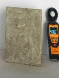


Figure(2),(a)Thedamagesampleiscalibrated,the undamagedcontrolsampleiscalibrated,andthe uncalibratedcontrolsampleiscalibrated.

International Research Journal of Engineering and Technology (IRJET) e-ISSN:2395-0056
Volume: 11 Issue: 09 | Sep 2024 www.irjet.net p-ISSN:2395-0072
On the other hand, utilizing the 2D coordinate system, As per Colombo and Felicetti (2007), the CIE-XYZ colour space is not dependent on any particular device. Consequently, chromaticity-based testing on CIE-XYZ values derived from the RGB parameters will be repeated and applied as a baseline. for future projects and image training. Furthermore, CIE-XYZ models closely resemble and reproduce the appearance of human eyesight. To translate RGB pixel values to CIE-XYZ values, one can employ neural networks and polynomial transformations. It has been discovered that polynomial transformations require less effort and time to achieve the same level of precision as the two methods mentioned above. The Z componentinmathematicsdealswithbrightness,whereas theX,Yelementprovidesthenecessarycolourinformation for the image to be examined. Lighting conditions have been shown to affect a picture's brightness more often thanitscolorinformation.
Therefore, it can help with the analytical visualization of the color shift trend if a chromaticity-based graph is plotted against the time of immersions for each attack involving acid, salt, and sulfate. By examining and contrasting the trend with the corresponding acid durability factor or reduction in strength loss, one can determinetheassociationbetweendurabilityperformance andimage-basedvisualization.Thismayopenthedoorfor

the creation of a degradation detection model based on images.

2.
The program "ImageJ" has been used to analyze calibrated images. Medical imaging commonly uses this Java-based, open-source image processing application. including radiological image processing and 3D live-cell imaging. It is frequently employed as a digital image processing technique in civil engineering research. When the corresponding calibrated photos are examined and
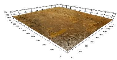
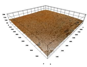
Fig.4.3Dplotsofdamagedsurfaceafterimmersionin5%ofhydrochloricacidforthedurationof(a)7days,(a)14days,(c)28days and(d)56days

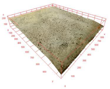


Figure.5.3Dplotsofdamagedsurfacesafterimmersionin5%ofsulfuricacidforthedurationof(a)7days,(b)14days,(c)28 daysand(d)56days

International Research Journal of Engineering and Technology (IRJET) e-ISSN:2395-0056
Volume: 11 Issue: 09 | Sep 2024 www.irjet.net p-ISSN:2395-0072


Figure.6.3Dplotsofdamagedsurfacesafterimmersionin5%ofaceticacidforthedurationsof(a)7days,(b)14days,(c)28 daysand(d)56days

(a)


Figure.7.3Dplotsofdamagedsurfacesafterimmersionin5%ofsodiumchlorideforthedurationsof(a)7days,(b)14days (c)28daysand(d)56days.
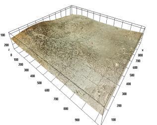
thecorresponding3Dsurfacemapsarecreated,thedegree of degradation for each individual immersion after 7, 14, 28,and56dayscanbeseen.
The images on each of the The concrete cube sample underwent calibration and inspection on its six faces.Theconcretesamplecube'smostdamagedfacesare depicted in Figures (4–7) following a certain length of immersion time for a certain acid exposure. Figure 4 illustratesthedamageand variationsin extentafter being immersed in hydrochloric acid for the designated periods of time. Visual analysis of these calibrated surface plots shows a clear color shift toward red. Ettringite is generatedwhensubjectedtosulfuricacid(Figure5)dueto the chemical reaction between the acid and calcium hydroxides, which is recognized to induce deterioration.This is confirmed by the visible shift toward thewhiteshiftobservedin thephotographsofthesample treated to sulfuric acid. As seen in Figures 6 and 7, respectively, exposure to acetic acid and sodium chloride resulted in early saturation-induced discolouration followed by the formation of pale yellow and white patches. The dynamic color changes throughout the ensuingdurations,however,arebarelyperceptible.
In color systems like each colour is denoted by a set of values (x, y, z) in the *CIE 1931 XYZ* colour space. which describehowthecolorisperceivedbythehumaneye.The chromaticitycoordinatesxandyaretypicallyused,withz beingderivedasz=1-x-y.Thesecoordinateshelplocate thepositionofacoloronachromaticitydiagram,allowing for easy comparison and understanding of the relationships between different colors.A chromaticity diagram is a two-dimensional plot where the x and y chromaticity coordinates are graphed. It represents the range of all visible colors. The boundary of the diagram corresponds to the “spectrum locus”, where pure spectral colors lie (ranging from violet to red). White light lies at thecenterofthediagramandrepresentstheequalmixture of red, green, and blue light. Colors inside the diagram represent combinations of these spectral colors, with *hue* being indicated by the position on the curve and *saturation*bythedistancefromthewhitepoint.
Created by the International Committee on Illumination (CIE), the CIE 1931 XYZ Colour Space this model represents color as a combination of three primary

International Research Journal of Engineering and Technology (IRJET) e-ISSN:2395-0056
Volume: 11 Issue: 09 | Sep 2024 www.irjet.net p-ISSN:2395-0072
components (X, Y, and Z), with chromaticity derived by normalizingthecolorvalues.
The steps to create a chromaticity diagram are as follows:
(a) To begin, extract the RGB colour data from the calibrated photograph of the deteriorating concrete surface. The method for achieving this is to take the average RGB value of a subset of pixels that best capture theimage'scolourprofile.
(b) Utilising polynomial transformations developed by (Cowan,1983),onecanconverttoXYZcolourspace.:
X=0.41245.R+0.35758.G+0.18042.B (1)
Y=0.21267.R+0.71516.G+0.07217.B (2)
Z=0.01933.R+0.11919.G+0.95023.B (3)
where R, G, B represents the corresponding colour coordinatesinRGBcolourspace.
(c) In order to counteract the impact of illumination, that sincex+y+z =1ifwetakenonlytwocoordinates,xandy, are needed for the chromaticity diagram. The z value can beinferred
x=X/(X+Y+Z) (4)
y=Y/(X+Y+Z) (5)
The first goal was to identify the pixels that most accurately captured the colour data regarding the surface deterioration.
There are several approaches to choosing the area of interest. It is thought that the pixels there contain the colour data of the zone that is fascinating and can convey the colour information about damage overall. Depending on the needs of the project, a rectangular or randomly chosen pixel-based zone of interest was chosen (Figure 3).Depending on theneeds oftheproject,a rectangular or randomly chosen pixel-based zone of interest was chosen (Figure3).
Followingthecreationofthesamplesdippedintheproper solutions, and analysis was performed to create the chromaticitydiagrams.assesshowthecolorprofilesofthe samples varied for each solution for each of the predetermined immersion times. Additionally, changes in
colorprofileswereassessedforeachsamplesubmergedin eachsolutionforeachimmersiontime.
A few inconsistent values that differed significantly from After examining the x, y readings of the data points collected from the specimen faces during immersion in hydrochloric acid, the mode x, y readings of the example faces at that specific immersion length were discovered.Thesevaluesweredisregardedsincetheyonly show localized damage caused by the hydrochloric acid attack,ratherthanofferingcolorinformationfortheentire affectedsurface.
Figure-8,Thegraph presentsthechromaticitycoordinates (x, y) of the control sample and the samples treated with hydrochloricacid(HCl)over differentdurations: 7,14,28, and56days.Thecontrolsampleispositionedloweronthe graph, serving as a baseline for comparison against the HCl-treatedsamples.
A gradual shift in chromaticity is observed in the samples exposedtoHCl,withthemagnitudeofthisshiftincreasing over time. After 7 days of exposure, the sample shows a slight deviation from the control, indicating the onset of acid-induced changes. This trend continues with the 14daysample,whichshowsafurtherincreaseinbothxandy values,suggestinga progressivereactionbetweentheacid andthematerial.
The most significant changes are observed in the 28-day and 56-day samples, with the 56-day sample showing the redshiftinfigure4onthesurfaceplots.Thisindicatesthat prolonged exposure to HCl intensifies the alteration of the material's color properties. The changes in chromaticity are likely the result of surface reactions and material degradation, which become more evident as the exposure durationincreases.
Figure-9, The graph illustrates the effect of sulfuric acid (H2SO4) exposure on samples over time. The x-axis likely represents a measure such as concentration or exposure level, while the y-axis shows a response, perhaps indicating a change in material properties. Different symbols represent the control sample and samples exposed to sulfuric acid for varying durations: 7, 14, 28, and56days.
The control sample has the lowest values on both axes, serving as a baseline. After 7 days of exposure, there is a slight increase in both the x and y values, indicating a minor change in the material’s properties. The 14-day sample shows behavior very similar to the 7-day sample, with only minor changes from the control. The sample

Volume: 11 Issue: 09 | Sep 2024 www.irjet.net p-ISSN:2395-0072
exposed for 28 days shows a white shift on the (figure-5), suggesting some response, though not as significant. After 56 days, the top surface of concrete got worn out then inside surface is visible at materials, then the surface of concreteisvisibleatwhitecolor.Whenthecolorincreases compared to the shorter exposure times, suggesting a different material response, possibly degradation or a chemical change. The results suggest that short-term exposure (7–14 days) leads to a steady increase in the measuredproperties.However,afterlongerexposure(28–56days),thematerial'sbehaviorchanges.Thelarge white shift on the x-axis after 56 days, combined with the drop on the y-axis, could indicate significant structural degradationoralteredchemicalproperties.
Fihure-10, The graph illustrates the effect of acetic acid (CH₃COOH) exposure on samples over time. The x-axis likely represents exposure duration or concentration, whilethey-axisshowsthematerial'sresponse,potentially reflecting changes in physical or chemical properties. The symbols represent the control sample and those exposed for 7, 14, 28, and 56 days. The control sample has the lowest values on the x-axis, establishing the baseline for comparison. After 7 days, there's a slight increase on both axes,indicatingthatthematerialbeginstoshowareaction to the acetic acid. The 14-day sample shows a further increase,suggestingthatthematerialcontinuestorespond to the acid. This sample shows minimal change from the 28-day sample, indicating that the material’s response begins to stabilize. After 56 days, there is little to no variation from the 28-day sample, indicating that the material has reached a steady state. In figure-6, when the magnitude of concrete when the colour is shifted at pale yellow at the duration of 56 days of exposure condition. The graph suggests an initial phase of change in the material in response to acetic acid exposure, particularly within the first 14 days. However, beyond this point, the material’s response begins to plateau, as indicated by the similarity between the 28- and 56-day samples. This stabilization suggests that the material reaches a point of equilibrium, where prolonged exposure no longer significantlyaltersitsproperties.
In figure-11 The graph illustrates the effect of sodium chloride(NaCl)exposureonsamplesovertime.Thex-axis likely represents a concentration or exposure-related factor, while the y-axis reflects the material's response. Each symbol represents a different sample: a control and samples exposed to NaCl for 7, 14, 28, and 56 days. The controlsampleispositionedaround0.32onthex-axisand 0.35 on the y-axis, serving as the baseline. The 7-day exposure sample shows a very slight change from the control, with only a minor shift in the y-axis value. The
sample exposed for 14 days remains virtually the same as the 7-day sample, showing no significant deviation from thecontrol.After28days,thesamplestillexhibitsminimal change,maintainingalmostthesamevaluesasthecontrol and other samples. The 56-day sample also shows no noticeable difference from the control or other exposed samples. In figure-7 the suface of concrete is there is no change in colour shift when the concrete is visible at light white changes on surface. The data suggests that sodium chlorideexposureovertimehasnosignificanteffectonthe material. Across all time periods (7, 14, 28, and 56 days), the samples show nearly identical values to the control, indicating that the material is resistant to NaCl and does notundergosignificantchangesordegradation.
Therelationshipbetweenthesamples' ofresidual compressivestrengthsandtheircorrespondingxvaluesof following varying immersion times in their respective solutions and the chromaticity data points wasexamined usingananalysis.
In the figure12, The 3D polynomial fits the data perfectly, as shown by the R2 = 1value. This indicates the data follows a complex pattern. The 2D polynomial provides a reasonable but less accurate fit with an R2of 0.7156, capturing part of the trend but not all of the details. Overall, the cubic model is more accurate, while the quadratic model is a simpler but less precise approximationofthedata.
Inthis case when thefigure-13wediscussthe resultsare, HCl immersion consistently weakens thematerial,causing asteadydecreaseincompressivestrength.NaClandH₂SO₄ immersions show more complex, non-linear responses, with compressive strength initially increasing before declining. H₂SO₄ immersion, in particular, leads to a rapid degradationafteraninitialstrengthpeak.intheaceticacid thissuggeststhatimmersioninCH3COOHinitiallyreduces the materials compressive strength, but after a certain point,thestrengthbeginstorecover.Thiscouldreflectthe material undergoing degradation, followed by a stabilizationoradoptionprocessintheaceticacid
These results highlight that different chemical environments have varying impacts on the material’s compressive strength, with each chemical causing degradationinuniqueways.
The compressive strength of NaCl is to starts around 27 MPa, peaks near 29 MPa, and then decreases, showing somevariationacrossthex-values(0.315–0.33).

International Research Journal of Engineering and Technology (IRJET) e-ISSN:2395-0056
Volume: 11 Issue: 09 | Sep 2024 www.irjet.net p-ISSN:2395-0072
Compressive strength values decrease consistently from around 30 MPa to 20 MPa over the x-values (0.3–0.38), suggesting that HCl immersion negatively affects the material'sstrength.
Compressive strength starts low, rises to approximately 29.51 MPa, then sharply declines beyond 0.4 x-value, suggestinganonlinearresponsetoH₂SO₄immersion.
The compressive strength of concrete decreases initially upon immersion in CH3COOH, followed by a partial recovery after reaching a value of x is 0.352 the value is
slightly decreases, then the compressive strength is decrease at liner variation the value is 26.13 when comparedtocontrolsamplethevalueisdecreased.

International Research Journal of Engineering and Technology (IRJET) e-ISSN:2395-0056
Volume: 11 Issue: 09 | Sep 2024 www.irjet.net p-ISSN:2395-0072 © 2024, IRJET | Impact Factor value: 8.315 |
acid control sample 7 days HCl 14 days HCl 28 days HCl 56 days HCl

Figure-8:chromaticitydiagramof(a)controlsampleanddeterioratedsurfaceowingtohydrochloricacidimmersionat5 % concentrationafter(b)7days,(c)14days,(d)28daysand(e)56days.
Sulpheric acid

H2SO4 7 DAYS
H2SO4 14 DAYS
H2SO4 28 DAYS
H2SO4 56 DAYS
Figure-9:chromaticitydiagramof(a)controlsampleanddeterioratedsurfaceowingsulfuricacidimmersionat5 % concentrationafter(b)7days,(c)14days,(d)28daysand(e)56days.

International Research Journal of Engineering and Technology (IRJET) e-ISSN:2395-0056
Volume: 11 Issue: 09 | Sep 2024 www.irjet.net p-ISSN:2395-0072

CONTROL SAMPLE
CH3COOH 7 DAYS
CH3COOH 14 DAYS
CH3COOH 28 DAYS
CH3COOH 56 DAYS
Figure-10:chromaticitydiagramof(a)controlsampleanddeterioratedsurfaceowingaceticacidimmersionat5 % concentrationafter(b)7days,(c)14days,(d)28daysand(e)56days.
Sodium chloride

CONTROL SAMPLE
NACL 7 DAYS
NACL 14 DAYS
NACL 28 DAYS
NACL 56 DAYS
Figure-11:chromaticitydiagramof(a)controlsampleanddeterioratedsurfaceowingsodiumchlorideimmersionat5 % concentrationafter(b)7days,(c)14days,(d)28daysand(e)56days.

International Research Journal of Engineering and Technology (IRJET) e-ISSN:2395-0056
Volume: 11 Issue: 09 | Sep 2024 www.irjet.net p-ISSN:2395-0072
Table. 6 Polynomial curves of second –and third degree relations correlating the x, y co-ordinates with respective solutions on concrete with r-squared values
Polynomial equation
Figure12 polynomialcurvescorrespondingtothex,y chromaticitycoordinatesofsamplessoakedin5%of sodiumchloride7,14,28and56days.

International Research Journal of Engineering and Technology (IRJET) e-ISSN:2395-0056
Volume: 11 Issue: 09 | Sep 2024 www.irjet.net p-ISSN:2395-0072
FortheimmersionofHCltochangethecolourin red shift after 56 days of duration and the top surface of concrete is visible for sandy type, then immersion of H2SO4 the top surface became worn down and is exposed. in white colour and lightgrey the the inside surface is visible. Then immersion of CH3COOH the top surface of concrete in colour visible for pale yellow there is no loss in strength. Then immersion of NaCl there is no change in strength then compare to normal cube it is little bit of change in colour as white the the top surface is visibleasnormalcube.
Figure-13.Thepolynomialcurvesrelatingcolour(x)to thecorrespondingtocompressivestrengthvaluesfor samplesofimmersedinthecorrespondingreagentsat 5%concentrationfor 7,14,28and56days
Drawing on the colorimetric technique experimental studyofconcretedeterioration,thefollowingconclusions canbedrawn.
When the immersion of concrete cubes on the chemicals, the strength will be loss, when compare to control cube HCl-29.38%, H2SO439.8%,CH3COOH-11.5andNaCl-9.35willbereduced thestrengthafter56daysofimmersion.
HCl immersion leads to the most consistent and steady reduction in compressive strength, highlighting its corrosive nature. NaCl and H₂SO₄ show more complex behaviour’s, with NaCl leading to moderate degradation, while H₂SO₄ causes a sharp and severe decrease after an initial strengtheningphase.
These results suggest that materials exposed to these chemical environments will degrade differently, with HCl being the most predictably damaging, and H₂SO₄ potentially causing more sudden and severe damage after prolonged exposure.A comparative analysis chromaticity diagramsandthree-dimensionalsurfaceplotsofthe surfaces that were corroded from immersion in sulphuric and hydrochloric acids, acetic acid and sodium chloride for durations of 7, 14, 28 and 56 days were made. It can be concluded that the qualitative description of It is appropriate to translate the colour information from the damaged surface into quantifiable values so that a mathematical analysis of the colour shift may be performed.
The characteristics of colour profile alterations in samples submerged in sodium chloride and hydrochloricacidoraceticacidandsodiumchloride are similar in nature, but the amount to which each degradation contributes to the alteration in colour profile relies on the rate at which the reagent is absorbed by the sample.concentrations to initiate chemical reactions and the corresponding rates of theirreactivity.
The correlation between the samples’ chromaticity ‘x’ values with their residual strengths for samples immersed in hydrochloric acid and aceticacidweresimilar.
The type of correlation that exists in the instance ofimmersion in sulfuric acid and sodium chloride, though similar, differs in their respective degrees of correlation and can be attributed to the rateofdegradation.
V. Guru Prathap Reddy * , T. Tadepalli , Rathish Kumar Pancharathi Hue-Saturation-Intensity colour space-based, non-destructive evaluation of concrete deterioration through surface imaging published in May2022byElsevier.
M. Abed, J. d e Brito, Journal of Building Engineering: Nondestructive testing is used to evaluatehigh-performanceself-compactingconcrete that is exposed to elevated temperatures and uses alternativematerials.32(2020)101720.
Yao, C., et al. bridge crack picture detection and classification method based on climbing robots. 2016 TCCT.
Valença, J., et al., The evaluation of fractures on concrete bridges is done by image processing and a laser scanning survey. 146: pp. 668–678, ConstructionandBuildingMaterials,2017.
Liu, X., Y. Ai and S. Scherer, Strong image-based fracture identification in concrete structures with

International Research Journal of Engineering and Technology (IRJET) e-ISSN:2395-0056
Volume: 11 Issue: 09 | Sep 2024 www.irjet.net p-ISSN:2395-0072
visual characteristics and multi-scale improvement. 2017.
Yang, Y., et al., Method of image analysis for estimating the width and distribution of cracks in reinforced concrete structures. Automation in Construction,2018,91,120–132.
Talab,A.M.A.,etal.,imageprocessingtechniques such as multiple filtering and the Otsu method for picture detection of cracks. The 2016 edition of Optik: International Journal for Lighting and Electron Optics, volume 127, issue 3, pages 1030–1033.
Xuxuejunandzhangxiaoning, Theuseofdigital images for crack identification in concrete bridges was reported in the Journal of Hunan Universities (NaturalScienceEdition)in2013;pages34–40.
Zhang, X., et al. (2017). Automated Image Processing for Crack Identification in Concrete Structures.JournalofCivilEngineering.
Liu, Y., et al. (2020). Deep Learning for Crack FindinginConcreteConstructions.Materialsfor ConstructionandBuilding.
Li, H., et al. (2019). Surface Defect Detection in ConcreteUsingTextureAnalysis.Sensors.
Patel, R., & Singh, A. (2021). Color Image Processing for Monitoring Chemical Reactions in Concrete.JournalofBuildingPerformance.
Kuo, C., et al. (2018). Time-lapse Imaging for Crack Growth Analysis in Concrete. Materials and Structures.
Huang, J., et al. (2022). Subsurface Defect Detection in Concrete Using Thermal Imaging and ImageProcessing.NDT&EInternational.
Wang, J., et al. (2020). Quantitative Measurement of Concrete Defects Using Image Processing.IEEETransactionsonImageProcessing.
Johnson, M., et al. (2019). Real-time Monitoring of Concrete Structures Using Image Processing. AutomationinConstruction.
Brown,T.,&Green,P.(2023).DataVisualization andIntegrationforConcreteHealthMonitoring. JournalofStructuralHealthMonitoring.
Chen,Q.,etal.(2021).PredictiveMaintenanceof Concrete Structures Using Image Processing Data. StructuralControlandHealthMonitoring.