
International Research Journal of Engineering and Technology (IRJET) e-ISSN: 2395-0056
Volume: 11 Issue: 09 | Sep 2024 www.irjet.net p-ISSN: 2395-0072


International Research Journal of Engineering and Technology (IRJET) e-ISSN: 2395-0056
Volume: 11 Issue: 09 | Sep 2024 www.irjet.net p-ISSN: 2395-0072
Adity Sharma1 , Ghanshyam Dhanera2 , Purushottam Sahu3 , Ravi 4
1Research Scholar,
2Ghanshyam Dhanera, Professor, Dept. of Mechanical Engineering, BM College, MP, Indore
2Purushottam Sahu, Professor, Dept. of Mechanical Engineering, BM College, MP, Indore
Abstract - The increasingdemandfor high-headfluidsupply in today's industrial revolution and fast-paced world makes multistage pumps an essential component in various applications. Theirgrowingpopularitystemsfromtheirability to efficiently handle high-head requirements. Performance analysis and head loss evaluation of these pumps are crucial not only for economic reasons but also for energy conservation, given that multistage pumps account for approximately 22 percent of global energy consumption.
This studyaims to analyze headlossesindifferentcomponents ofmultistage pumps andinvestigate howthe number ofvanes in the diffuser affects these losses under various operating conditions. A numerical simulation analysis of a two-stage centrifugalpump was conductedto achieve this objective.The results focus on the head loss and performance parameters of the two-stage centrifugal pump, providing valuable insights into optimizing pump design and operation for better efficiency and reduced energy consumption.
Key Words: Multistage pump, Impellers, Diffuser, Return Channels
1. INTRODUCTION
1.2 CENTRIFUGAL PUMPS
Arotdynamictypeofpumpisacentrifugalpump.It operates on the forced vortex theory. A centrifugal pump usescentrifugalforcetocarryoutpumpingoperations.The impeller,whichhasseveralmountedvanes,rotatesaboutan axisandcausesliquidtobethrownoutwardbycentrifugal force,resultinginthecreationoftwodistinctpressurezones along the impeller's radial direction. Liquid flow is made possiblebytheimpeller'scenterhavinglowerpressurethan itsouteredges,whichhavehigherpressure.
The inlet pipe, impeller, diffuser or volute casing, and outflow pipe are a centrifugal pump's primary parts. Industrial, home, and other uses for centrifugal pumps include power plants, among others. These work within a specificrangeofdischargeandaredesignedinaccordance withtheapplication.Radialflowpumps,axialflowpumps, mixedflowpumps,singlestagepumps,multistagepumps, etc.aresomeofthesubtypesofcentrifugalpumps.
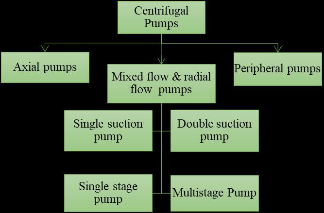
Figure 1.4: Classificationofcentrifugal.
Centrifugalpumpsrepresentadynamicclassofmachinery employedtofacilitatetheconveyanceanddisplacementof fluidsinamyriadofindustrial,commercial,andresidential contexts. Relying on the centrifugal force principle, these pumps harness rotational energy to endow the fluid with kinetic energy, subsequently translated into pressure energy.Theiroptimalperformanceisparticularlynotablein scenarios characterized by elevated flow rates and moderate-to-highheaddemands.
Salientattributesandcharacteristicsofcentrifugal pumps encompass:
Impeller Mechanism: Central to centrifugal pumps is the impeller acorerotatingelement.Theimpeller'srotation within the pump housing engenders centrifugal force, propelling the fluid outward radially from the impeller's nucleus.
EnergyTransformation:Theoutwardpropulsionofthefluid by the impeller augments its velocity, resulting in the conversionofmechanicalenergyintokineticenergy.
Pressure Generation: Subsequent to the kinetic energy infusion, the fluid's energy metamorphoses into pressure energy upon interaction with stationary pump casing componentslikethevoluteordiffuser.
SuctionandEjection:Fluidingressoccursthroughaninlet, oftendesignatedasthesuctionport.Thepressurizedfluidis thenexpelledthroughanoutletordischargeport.

International Research Journal of Engineering and Technology (IRJET) e-ISSN: 2395-0056
Volume: 11 Issue: 09 | Sep 2024 www.irjet.net p-ISSN: 2395-0072
SingleStageandMultistage:Centrifugalpumpsareavailable in both single-stage and multistage configurations. Singlestage pumps incorporate a single impeller and are wellsuited for tasks requiring lower head requirements. In contrast, multistage pumps feature multiple impellers to catertoapplicationswithelevatedheaddemands.
Versatile Applications: Centrifugal pumps exhibit broad utilityacrossdomainsencompassingwatersupply,sewage systems,industrialoperations,HVAC(heating,ventilation, and air conditioning), irrigation, and petroleum refining, amongothers.
EfficiencyandPerformance:Factorssuchasimpellerdesign, pumpspeed,andfluidattributesinfluencepumpefficiency. Manufacturersfurnishperformancecurvesillustratingthe nexus betweenflowrate,head,andefficiencyspecific toa givenpumpmodel.
Cavitations Vulnerability: A susceptibility to cavitations exists in centrifugal pumps a phenomenon arising when pump pressure drops below the fluid's vapor pressure. Vaporbubbleformationoccurs,andthesebubblescollapse upon encountering higher-pressure regions, potentially causingdamagetopumpcomponents.
Insummary,thefunctioningofcentrifugalpumpspivotson the conversion of mechanical energy into kinetic and pressure energy through impeller rotation. Their adaptability,efficacy,andcapabilitytoaccommodatediverse flow rates and head needs establish them as fundamental constituents in the realm of fluid conveyance, spanning a gamutofindustries.
The term "multistage pump" refers to a particular kind of centrifugalpumpthatconsistsofseveralimpellersinstalled onasingleshaftandlinkedinseries,asseeninfigure1.5. Thissetupisprimarilyusedtoachievehigherheadthana singlestagepump.Eachstageofamultistagepumpismade upofanimpeller,adiffuser,andareturnchannel.
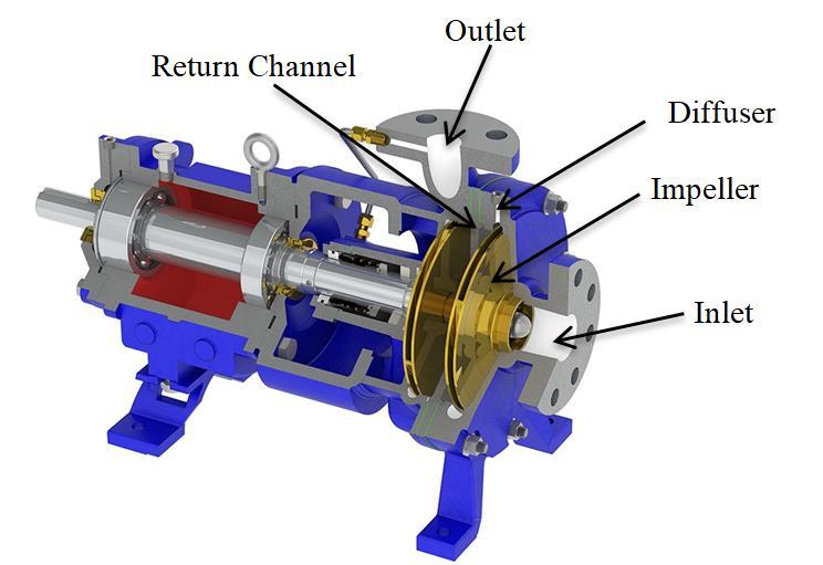
Number of stage: Oneimpeller,onediffuser,andonereturn channelmakeupastageofamultistagepump.Amultistage pump'sheadgenerationisboostedbycouplingtwoormore stagesinaseriesconnection.Theprimemoverisconnected to a single shaft on which the impellers of each stage are installed.
Assessthemultistagepump'sdesignandoptimization.
Runanumericalsimulationofatwo-stagemultistage pump by varying the number of diffuser vanes at differentdischarges.
Runanumericalsimulationofatwo-stagemultistage pump by varying the number of diffuser vanes at differentdischarges.
The work's scope:
Gatherdesigninformation(i.e.pumpsizing,boundary conditionsetc.).
Creatinga3DmodelofthemultistagepumpintheCreo parametric software, and meshing all of its parts in ICEM-CFD.
The preliminary processing and simulation of a twostagepumpwithvariousdiffuservanesanddischarges.
Resultsoftheheadlossandperformancemetricsofthe multistagepumpwereevaluatedandanalysed.
LAYOUT:
Chapter 1 Providesanintroduction topumps,centrifugal and multistage pumps, classification of pumps, and multistage pump components, followed by the thesis' structure.
Chapter 2 includes a survey of the literature on the numericalanalysisofthemultistagepumpandcentrifugal pumpcomponentdesigns.
Chapter 3 explains the multistage pump theory and the theoryunderlyingthenumericalsimulation.
Chapter 4 contains the multistage pump's geometric modelling and numerical simulation procedure, both of whichwerecompletedforthisthesis.
2.1 LITERATURE REVIEW
Up until the 1980s, the only means to evaluate the performance ofsuchcomplexfluidmachines wasthrough physicalmodeltesting.Ascomputationalprocessingcapacity increased,computationalfluiddynamics(CFD)emergedasa reliable and practical method. (Shah et al.2012)[16]. numerous researchers numerically and experimentally examinedvariousflowparametersinsidemultistagepumps toincreaseperformance.

International Research Journal of Engineering and Technology (IRJET) e-ISSN: 2395-0056
Volume: 11 Issue: 09 | Sep 2024 www.irjet.net p-ISSN: 2395-0072
Nagahara et al. (2005)[11] Largeeddysimulation(LES) wasutilizedtoinvestigatetheflowfieldinamultistage pumpandcomparethefindingswithexperimentaland CFDresults.Theinteractionbetweentheimpellerandthe statorwasconsideredthroughLEScalculations,enabling the study of the flow field in the input region of each component.Throughouttheexperimentalinvestigation, velocity distributions and pressure changes were capturedusinga scaledmodel pump. The ratiooftotal headtoexperimentalheadwas1.03intheLESapproach and1.04intheRANSmethod,bothofwhichdeviatedby only4%fromthetruehead.
Roclawski et al (2006)[14] ACFDsimulationwasrun, followed by an experimental test to confirm the CFD findings, in order to modify the diffuser to reduce the radial dimension of a multistage pump. They have modifiedthestatorinordertoreduceradialdimensions. Verificationoftheresultsisdoneusingmeasurementsof characteristiccurvesandinformationfromhotwires.At its peak efficiency, the new stator concept's pump performancewasaround7%lessefficientthantheoneit replaced.
Yang et al. (2009)[23]analysed multistage centrifugal pumpsusingintegralmodelling,comparedthefindings toexperimentaldata,andfoundonlysmallvariations.A flowchannelforamultistagepumpwasbuiltfromthe groundup.Theimpactofthegridnumberwasexamined throughcomparisonofthesimulationresults.Datawere utilised to evaluate thedistributions of pressure and speed in the impellers, guiding vanes, and other parts. Because the projected values agree with the observed values,itprovedthatintegralmodellingcanbeusedto numerically simulate flow in a multistage centrifugal pump.Lessthan10%,orwithinacceptablelimits,was discoveredtobetheinaccuracyintheintegralmodelling.
Tverdokhleb et al. (2012)[20]Using computer modelling, we have attempted to reduce the radial dimensiononmultistagepumpsbyloweringtheratioof guide vane external diameter to impeller external diameter.Increasingthenumberofvanesutilisedinthe impellor with a two-row vane arrangement allows for thedecreaseofD2.Whilekeepingtheotherperformance factorssame,theydecreasedtheradialdimensionby4%.
Streamline patterns for 7 diffuser vanes
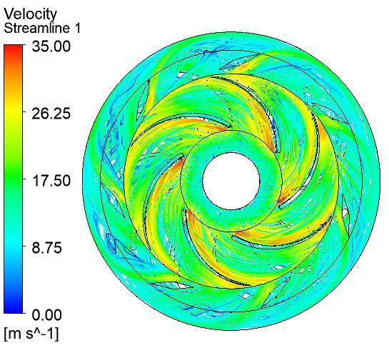
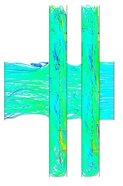
Figure5.21(a)and(b)showthevelocitystreamlinesfor seven diffuser vanes in the radial and axial planes, respectively. As we can see, the kinetic energy of the rotatingimpellercausesthefluidvelocityintheimpeller tobegreater.Inthediffuser,velocityisloweredby4.42 m/s.Inpumpflowchannels,asmoothflowisachieved.
5.7.2 Streamline patterns for 8 diffuser vanes
Figure5.22(a)and(b)showthevelocitystreamlinesfor eight diffuser vanes in the radial and axial planes, respectively. As we can see, the kinetic energy of the rotatingimpellercausesthefluidvelocityintheimpeller tobegreater.Inthediffuser,velocityisloweredby4.39 m/s.Inpumpflowchannels,asmoothflowisachieved.

International Research Journal of Engineering and Technology (IRJET) e-ISSN: 2395-0056
Volume: 11 Issue: 09 | Sep 2024 www.irjet.net p-ISSN: 2395-0072
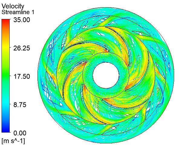

5.7.3 Streamline patterns for 9 diffuser vanes
Figure 5.23 (a) and (b) show velocity streamlines for nine diffuser vanes in the radial and axial planes, respectively. As we can see, the kinetic energy of the rotatingimpellercausesthefluidvelocityintheimpeller tobegreater.Inthediffuser,velocityisloweredby4.52 m/s.Inpumpflowchannels,asmoothflowisachieved.


5.7.4 Streamline patterns for 10 diffuser vanes
Figure5.24(a)and(b)showthevelocitystreamlinesfor 10 diffuser vanes in the radial and axial planes, respectively. As we can see, the kinetic energy of the rotatingimpellercausesthefluidvelocityintheimpeller tobegreater.Inthediffuser,velocityisloweredby4.51 m/s.Inpumpflowchannels,asmoothflowisachieved.

International Research Journal of Engineering and Technology (IRJET) e-ISSN: 2395-0056
Volume: 11 Issue: 09 | Sep 2024 www.irjet.net p-ISSN: 2395-0072

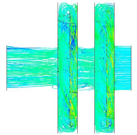
5.7.5 Streamline patterns for 11 diffuser vanes
Figure5.25(a)&(b)showthevelocitystreamlinesfor 11 diffuser vanes in the radial and axial planes, respectively. As we can see, the kinetic energy of the rotatingimpellercausesthefluidvelocityintheimpeller tobegreater.Inthediffuser,velocityisloweredby4.60 m/s.Inpumpflowchannels,asmoothflowisachieved.
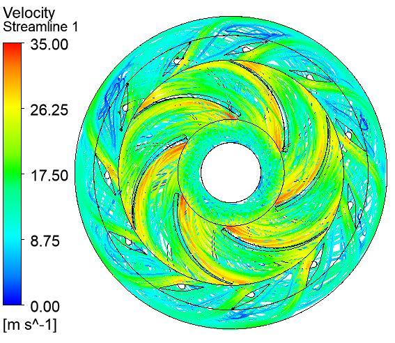
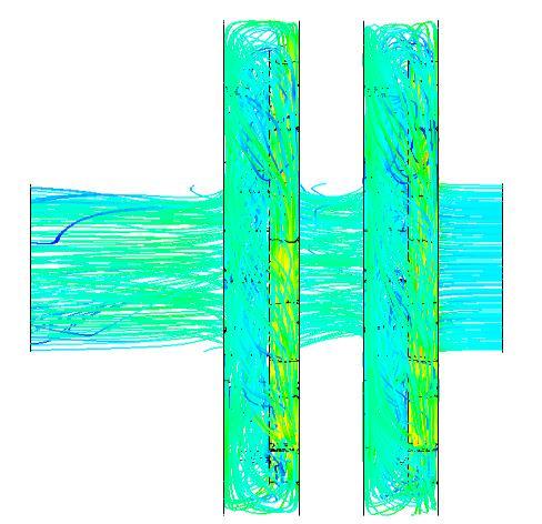
Basedonthesimulationresults,severalkeyconclusionscan bedrawn:
1. Efficiency at Different Diffuser Vane Numbers: At 1900 rpm with six different discharge rates, the diffuser with sevenvanesexhibitedboththehighestandlowestefficiency at a discharge of 630 m³/h. This suggests a significant sensitivity of efficiency to both the vane number and dischargerate.
2.ImpactofVaneNumber(Oddvs.Even):Diffuserswithan oddnumberofvanesgenerallyperformedbettercompared to those with an even number of vanes. This may be attributed to the relative angular positioning between the diffuservanesandtheimpellervanes,whichlikelyreduces adverseinteractions.
3.HeadConsistencyAcrossDischarges:Foralltestedvane configurations, the head values at discharges of 580, 630, and700m³/hwerenearlyidentical.Thisindicatesthatthe numberofvanesinthediffuserhasaminimalimpactonthe headathigherdischargerates.

International Research Journal of Engineering and Technology (IRJET) e-ISSN: 2395-0056
Volume: 11 Issue: 09 | Sep 2024 www.irjet.net p-ISSN: 2395-0072
4.InfluenceofDiffuserChannelSize:Thesizeofthediffuser channelhasasubstantial effectontheperformanceofthe multistagepump.Evensmallreductionsinchannelsizecan significantly impact overall performance, highlighting the importanceofoptimizingthisparameter.
Thesefindingscanhelpguidethedesignandoptimizationof diffuser vanes in multistage pumps, balancing efficiency, headconsistency,andoverallperformance.
1. Elikalfa, A, &Karaismail, E, (2019). “Design and optimization of a centrifugal pump impeller with ansys–optislang”. ARGE Dergisi
2. EuropeanCommission(2001).“Studyonimproving theenergyefficiencyofpumps”.
3. Gülich, J. F. (2008). “Centrifugal pumps”, Berlin: Springer, 02.
4. Hernandez-Solis, A., &Carlsson, F. (2010). “Diagnosis of submersible centrifugal pumps: a motor current and power signature approaches”. Epe journal,20(1),58-64.
5. http://equipmentschemical.blogspot.com/2014/01 /centrifugal-pumps-basic-concepts-of.html
6. https://smartturner.ca/pumps/multi-stage-heavyduty-pumps
7. https://www.pipeflow.com/software-technicalsupport/pipe-flow-expert-positive-displacementpumps
8. https://www.pumpsandsystems.com/whatdifference-between-centrifugal-rotodynamicpumps
9. Liu,M.,Tan,L.,&Cao,S.(2018).“Designmethodof controllable blade angle and orthogonal optimization of pressure rise for a multiphase pump”, Energies,11(5),1048.
10. Mosshammer,M.,Benigni,H.,Jaberg,H.,&Konrad,J. (2019). “Maximum Efficiency Despite Lowest Specific Speed Simulation and Optimisation of a Side Channel Pump”. International Journal of Turbomachinery, Propulsion and Power, 4(2),6.
11. Nagahara, T., Inoue, Y., Sato, T., Sakata, S., Nishimura, K., & Kato, C. (2005, January). “Investigationoftheflowfieldinamultistagepump by using LES”. In Fluids Engineering Division Summer Meeting 41987,1321-1329).