
International Research Journal of Engineering and Technology (IRJET) e-ISSN: 2395-0056
Volume: 11 Issue: 09 | Sep 2024 www.irjet.net p-ISSN: 2395-0072

International Research Journal of Engineering and Technology (IRJET) e-ISSN: 2395-0056
Volume: 11 Issue: 09 | Sep 2024 www.irjet.net p-ISSN: 2395-0072
Ravi
1, Ghanshyam Dhanera 2, Purushottam Sahu,3Adity Sharma4
1Research Scholar,
2Ghanshyam Dhanera, Professor, Dept. of Mechanical Engineering, BM College, MP, Indore
2Purushottam Sahu, Professor, Dept. of Mechanical Engineering, BM College, MP, Indore
Abstract - This study explores the application of additive manufacturingoptimizationtechniquestoachievethisweight reduction. Specifically, we investigate the use of lattice structures and topology optimization methods. The Finite Element Analysis (FEA) identifies critical areas with significant stresses and deformation. By employing lattice structure technology and topology optimization, we can significantly reduce the weight of the lower control arm. Ourfindingsindicatethat,amongvariousmethodsconsidered, the topology optimization approach is the most effective for minimizing the weight of the front lower control arm while maintaining its structural integrity.
Key Words: Topologyoptimization,frontcontrollowerarm
Additive Manufacturing
Industriessuchasaerospace,automotive,andhealthcareare increasingly adopting additive manufacturing due to its versatilityandefficiency.Thistechnologyisbeingappliedin anexpandingrangeofscenarios.Inthenextparagraph,we will delve deeper into the specific advantages of additive manufacturing compared to conventional production techniques.
Topologicaloptimizationisacomputationalapproachused tooptimizethemateriallayoutwithinagivendesignspace, subject to specific constraints and performance requirements.Thismethodaimstoachievethebestpossible structuralperformancebyredistributingmaterialtoareas whereitismostneededwhileremovingitfromareasthat arelesscritical.
Byapplyingtopologicaloptimization,designerscancreate lightweight, efficient structures that maintain or even enhance their strength and durability. This technique is particularly valuable in industries like aerospace, automotive,andcivilengineering,whereweightreductionis crucial for performance and efficiency. Topological optimization leverages advanced algorithms and finite element analysis (FEA) to identify optimal material distribution, resultingininnovativedesignsthatare often unattainablethroughtraditionaldesignmethods.
The Finite Element Method (FEM) is a computational approachusedtoaddressintricateengineeringchallenges bydecomposingacomplexsystemintosmaller,manageable elements known as finite elements. These elements are connected at specific points called nodes, forming a mesh that represents the entire system. FEM is instrumental in analyzingvariousphysicalphenomena,includingstructural mechanics,heattransfer,andfluiddynamics.
UsingFEM,engineerscansimulateandpredicthowadesign will behave under real-world conditions such as forces, vibrations,andthermaleffects.Thismethodoffersdetailed insightsintostressdistribution,deformation,andpotential failure points, which are crucial for optimizing designs to enhanceperformanceandsafety.FEMisextensivelyutilized insectorssuchasaerospace,automotive,civilengineering, andbiomechanics.
TheFiniteElementMethodfollowsastructuredapproachto solvingcomplexproblems,typicallyinvolvingthefollowing steps:
Identify the specific physical problem, such as structural stressanalysis,thermaldistribution,orfluidflow.
-Developageometricmodelthatrepresentstheproblem's physicaldomain.
- Break down the geometric model into smaller, finite elements,creatingamesh.Theseelementscanvaryinshape, suchastriangles,quadrilaterals,ortetrahedrons.
- Define nodes at the element corners and edges where calculationsforfieldvariableswilloccur.
- Choose the appropriate type of elements based on the problem's characteristics and the required precision. Common choices include 1D (bars), 2D (triangles,
International Research Journal of Engineering and Technology (IRJET) e-ISSN: 2395-0056
Volume: 11 Issue: 09 | Sep 2024 www.irjet.net p-ISSN: 2395-0072
quadrilaterals), and 3D (tetrahedrons, hexahedrons) elements.
4. Derivation of Element Equations**
Formulatethegoverningequationsforeachelement,usually basedonprincipleslikeequilibrium,conservationlaws,or materialproperties.
Construct the element stiffness matrix, load vector, and othernecessaryattributes.
5.AssemblyoftheGlobalSystem
-Integratetheindividualelementequationsintoaglobal systemrepresentingtheentireproblemdomain,combining alltheelementstiffnessmatricesandloadvectors.
6.ApplicationofBoundaryConditions
Apply the boundary conditions to the global system to simulate the physical constraints of the problem, such as fixedsupports,prescribeddisplacements,orappliedloads.
7.SolutionoftheSystemEquations
- Solve the global system using numerical methods to obtain the values of field variables at the nodes. Common methodsincludedirectsolverslikeGaussianeliminationor iterativesolverssuchastheconjugategradientmethod.
8.Post-ProcessingofResults
- Analyze and visualize the results, often by generating plotsofdeformedshapes,stressdistributions,temperature fields,etc.
Perform further calculations if needed, such as deriving secondaryquantitieslikestrainorflux.
9.VerificationandValidation
-Verifytheresultsforconvergenceandaccuracy.
- Validate the model by comparing FEM results with experimental data or analytical solutions to ensure its reliability.
FEMisaversatilecomputationaltoolemployedinvarious engineering and applied science fields. Key applications include:
1. Structural Analysis
Civil Engineering: Design and analysis of infrastructure such as buildings, bridges, and dams. FEM helps assess stress,strain,anddisplacementunderdifferentloads.
-Mechanical Engineering*: Analysis of components like beams, frames, and shells, crucial in designing machinery, vehicles,andaerospacestructures.
2.ThermalAnalysis
Heat Transfer: FEM models conduction, convection, and radiation heat transfer in solids and fluids, applied in electronicscooling,heatexchangers,andinsulationdesign.
- Thermal Stress*: Analyzing stresses and deformations duetotemperaturechanges,essentialindesigningturbines, engines,andreactors.
3.FluidDynamics
ComputationalFluidDynamics(CFD)*:FEMsimulatesfluid flow and heat transfer in fields like aerodynamics, hydrodynamics,andprocessengineering.
- Multiphase Flows*: Studying interactions between different fluid phases, such as in oil and gas extraction, chemicalprocessing,andenvironmentalengineering.
4.ElectromagneticAnalysis
Electromagnetic Fields: FEM assists in designing and analyzingelectricandmagneticfieldsindeviceslikemotors, transformers,andsensors.
-WavePropagation*:Usedintelecommunications,radar, andmicrowaveengineeringtostudyelectromagneticwave behavior.
5.Acoustics
-NoiseControl*:Appliedindesigningsystemsforreducing noise in automotive, aerospace, and architectural applications.
- *Vibration Analysis*: Evaluating mechanical system vibrations to prevent resonance and ensure structural integrity.
6.Biomechanics
Medical Implants: FEM is used to design and analyze implantssuchashipjointsanddentalprosthetics,ensuring theirstrengthandbiocompatibility.
- Biomechanical Analysis*: Studying the mechanical properties of biological tissues like bones, muscles, and organs.
7. Manufacturing Processes
Metal Forming*: Simulating processes like forging, stamping,androllingtooptimizematerialflowandminimize defects.
International Research Journal of Engineering and Technology (IRJET) e-ISSN: 2395-0056
Volume: 11 Issue: 09 | Sep 2024 www.irjet.net p-ISSN: 2395-0072
AdditiveManufacturing:Analyzinglayer-by-layermaterial addition to predict stresses, deformations, and thermal behavior.
8. Geotechnical Engineering
Soil-StructureInteraction*:Analyzingfoundations,tunnels, andretainingstructurestoensurestabilityandsafety.
Seepage Analysis*: Studying groundwater flow and its effectsonstructuresandenvironmentalsystems.
9. Aerospace Engineering
AircraftDesign*:Analyzingairframestructures,wings,and fuselage to ensure safety and performance under aerodynamicloads.
Spacecraft Components Studyingthermalandmechanical stressesinsatellitecomponentsandspacestructures.
10. Energy Sector
WindTurbines*:Structural andfluiddynamicsanalysisof windturbinebladesandtowers.
Nuclear Reactors*: Thermal and structural analysis of reactorcomponentstoensuresafeoperationunderextreme conditions.
11. Automotive Industry
CrashSimulation:Evaluatingvehiclecrashworthinessand occupantsafetyduringcollisions.
Engine Components: Thermal and structural analysis of enginepartstoimproveperformanceandlongevity.
FEM’saccuracyandadaptabilitymakeitacrucialtoolforthe design, analysis, and optimization of complex systems in thesediversefields.
Dr.J.Mahishi[1]thisarticleisapartofacomprehensivestudy thatinvestigatesvariousfactorsleadingtomaterialfailure, withaspecificfocusonmechanicalfailures.Allinstancesof failure can be attributed to human error. The three most prevalenttypesofhumanerrorareerrorsofcomprehension, errorsofaction,anddeliberateerrors.Finiteelementanalysis is a highly efficient technique for analysing mechanical structures,asitscrutinisestheentirestructureasamultitude ofsegments.Thestatusofeachcomponentisdeterminedby applyingmathematicalsolutions,whicharethencombinedto determinetheoverallconditionofthestructure.
Kang,B.,Sin,H.-C.,&Kim,J.(2007)[2]Fracturemechanics aims to establish a mathematical framework for analysing failures caused by cracks and fractures. The relationship
betweenthesizeofadefect,theonsetofacrack,thelevelof stress applied, and the material's brittleness is established. Theaforementionedformulacanbeutilisedtocalculatethe maximum permissible fault size, the necessary breaking force,theloadexertedonthecomponentduringfailure,the materialsutilised,andthedesign'soverallquality. Thistool can be utilised to assess the magnitude of a defect and the durationittakesforthesubstancetodegrade.
Nawar A. Al-Asady [3] The objective of Finite Element Analysis(FEA)istodetermineadistinctsolutionforevery constituent of a system through the application of mathematicaltechniquesto elucidateintricateengineering problems. Finite Element Analysis (FEA) involves the mathematical estimation of the mechanical and physical behaviour of individual components. The present study involvesananalysisofthefundamentalFiniteElement
Analysis(FEA)ofatruss,whichisatypeofrod.
Sritharan.G,[4]Theobjectiveofthestudywastoassessthe accuracy of a vehicle suspension component model by comparingitwithexperimentaldata.Thiscomponentisan undercarriage arm designed for a vehicle equipped with a 2000cc engine. The component's critical point, loading conditions,andprojectedlifespanwereestablishedthrougha seriesofstress,strain,andweartests.Thestraindistribution resultingfromthetestingprocesswasdeterminedtobein agreement with the onecomputedthroughFiniteElement Analysis (FEA), despite the complexity of the component's shape. The information obtained from the road test was notablydistinctfromthefindingsoftheFEA.Toproperlycite asource,youneedtoincludetheauthor'sname,thetitleof thework,thedateofThearticletitled
"Crashworthiness, Simulation of Lower Control Arm" by MiguelwaspublishedintheSAEJournalinApril2005.The objective of the Finite Element Analysis (FEA) was to pinpointthecrucialareasofthecomponent.Themodelwas created using CATIA software, and subsequent strain and fatigueanalyseswereconductedusingMSCNastranandMSC Fatigue.
IiM.M.NoorandM.M.Rahman[5]Inordertofullyleverage the potential of FEA analysis, it is imperative to employ factualdatatoauthenticateitsprecisionandsoundnessinthe timesahead.Theresearchersidentifiedoptimallocationsfor strain sensors by analysing strain analysis data that was verifiedtobeaccuratebytheFEmodel.Itisrecommendedto collectexperimentaldataforeveryindividualcomponent.The frequency of injuries caused by fatigue was moderate per cycle,however,theoverallnumberofcyclesmorethanmade upforit.
International Research Journal of Engineering and Technology (IRJET) e-ISSN: 2395-0056
Volume: 11 Issue: 09 | Sep 2024 www.irjet.net p-ISSN: 2395-0072
TheFEAstructuralanalysisstepsaredescribedbelow:
TheCADmodelofthefrontcontrollowerarmwasgenerated utilizingthesketch,extrude, andpatternfunctionalitiesof theCreodesignsoftware.Thedesignoftheroboticlimbwas basedonexistingliterature.[30].
Figure4.1:CADmodeloffrontcontrollowerarm(generic design)
The CAD model of lattice design of front control lower is developedinCreoasshownin figure4.2below.Themodel isdevelopedwithlatticedesign
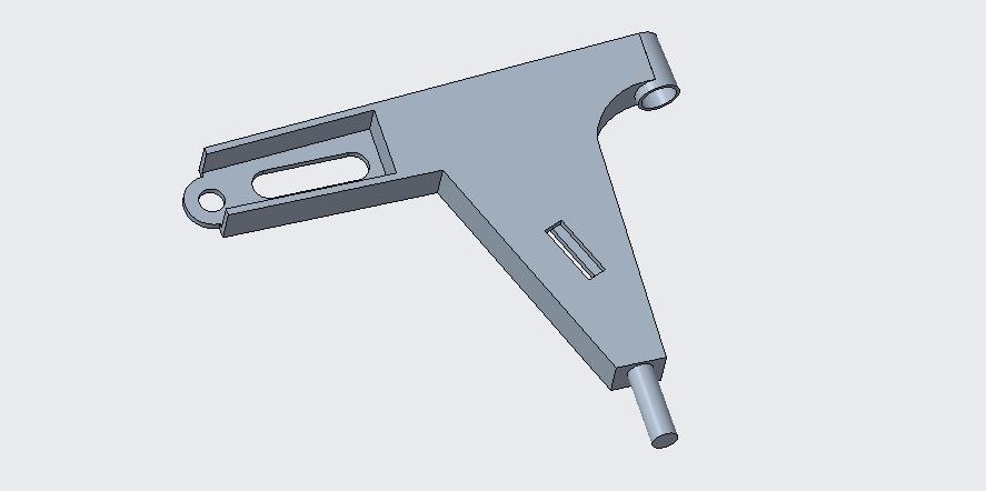
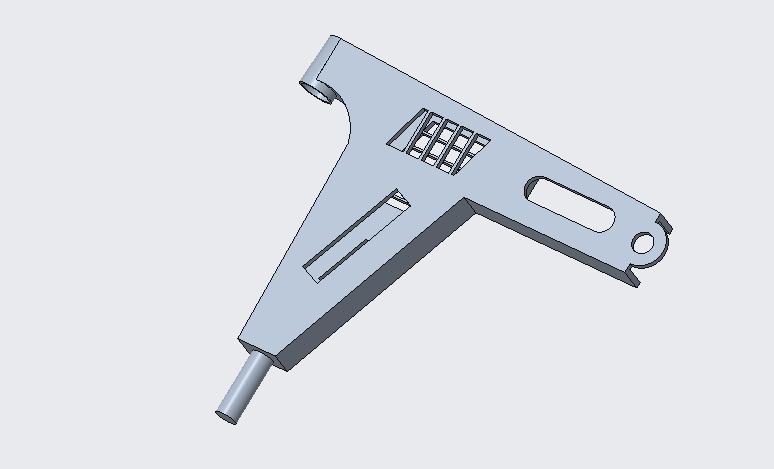
figure 4.2 below. The model is developed with lattice design
Figure 4.10 depicts the loads that are applied to the front control arm,as well astheboundary criteria thatmust be satisfied. A cylindrical region is outfitted with a fixed support, and a nodes chosen to take a point load with a magnitudeofthreethousandnewtons.
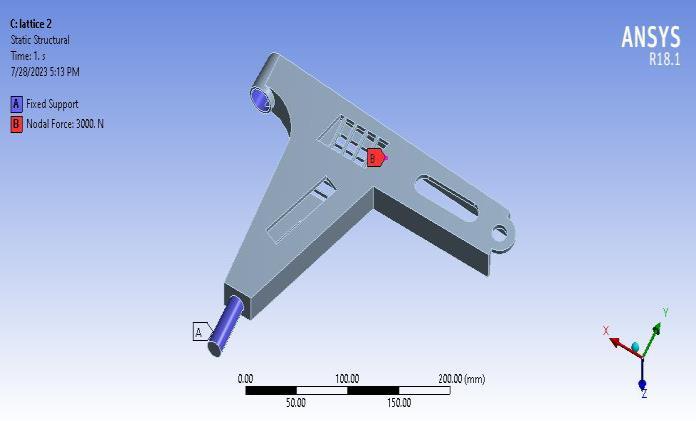
Figure 4.3: Loads and boundary condition on front control lower arm
TheFEAmodellingwascompletedusingthesparsematrix approach. The global stiffness matrix is the sum of the matricesforeachindividualcomponent.Resultsatnodesare oftenobtainedusingmatrixoperationslikeinversionsand multiplications, whereas results along the length of an element'sedgearetypicallyobtainedviainterpolation.
Theutmoststressthatcanbemeasuredatthepointwhere the burden is applied is 229.89 MPa. The yellow zone represents the location with the greatest level of tension. Thepresenceofadarkbluehueontheopposingsidesofthe lower front control arm indicates that the tension levels therearecomparable
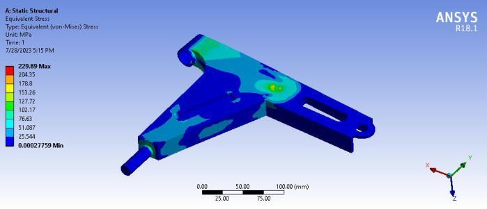
Figure 5.2 depicts the analogous tension observed in the generalfrontcontrolmechanism'slowercontrolarm
Table 5.1: Comparison table for front control lower arm

International Research Journal of Engineering and Technology (IRJET) e-ISSN: 2395-0056
Volume: 11 Issue: 09 | Sep 2024 www.irjet.net p-ISSN: 2395-0072
The deformation comparison plot is shown for different designs of front control lower arm. The maximum deformation plot is observed for lattice structure 2 and minimumdeformationisobservedfortopologicaloptimized design of front control lower arm. The minimum deformation obtained for topologically optimized is .2447mm.
Table5.1:Comparisontableforfrontcontrollowerarm
DesignType


5.3:Deformationcomparisonplot
Conclusion
The structural analysis is conducted on the front control lower arm using FEA. The critical regions of high stresses anddeformationareidentifiedfromFEAresults.Significant massreductionoffrontcontrollowerarmisachievedusing lattice structure technique and topology optimization technique.Thedetailedfindingsare:
Usinglatticestructure1,themassreductionoffrontcontrol lowerarmobtainedis 5.52%ascomparedtogenericdesign.
Usinglatticestructure2,themassreductionoffrontcontrol lowerarmobtainedis8.2%ascomparedtogenericdesign.
1.Thetopologyoptimizationtechniquehasbeenable to reduce the mass of front control lower arm by 45.85%.
2.Usinglatticestructure1,thedeformationoffront control lower arm obtained is 8.14% higher as comparedtogenericdesign.
1. D.KornackandP.Rakic,“CellProliferationwithout NeurogenesisinAdultPrimateNeocortex,”Science, vol. 294, Dec. 2001, pp. 2127-2130, doi:10.1126/science.1065467.
2. M. Young, The Technical Writer’s Handbook. Mill Valley,CA:UniversityScience,1989.
3. R. Nicole, “Title of paper with only first word capitalized,”J.NameStand.Abbrev.,inpress.
4. K.Elissa,“Titleofpaperifknown,”unpublished.
5. IiM. M. Noor and M. M. Rahman, Fatigue Life PredictionofLower SuspensionArmUsingstrainlifeapproach,©EuroJournalsPublishing,Inc.2009.
6. Roy,R.K.(2001).DesignofExperimentsUsingthe Taguchi Approach. New York, New York, United StatesofAmerica:JohnWiley&Sons,Inc.
7. Jong-kyu Kim, Seung Kyu Kim, Hwan-Jung Son, Kwon-HeeLee,Young-ChulPark,
8. “Structural design method of a control arm with considerationofstrength”,ACACOS'10Proceedings of the 9th WSEAS international conference on applied computer and applied computational science,2010,pp149-152.
9. Kwon Hee Lee, Xue Guan Song, Han Seok Park, YoungChulPark,“Lowercontrolarmoptimization applicationofresponsesurfacemodel andkriging model to ADI”, CSO '09 proceedings of the 2009 international joint conference on computational sciences and optimization ,Vol.2, 2009, pp 10131016.