
International Research Journal of Engineering and Technology (IRJET) e-ISSN: 2395-0056
Volume: 11 Issue: 09 | Sep 2024 www.irjet.net p-ISSN: 2395-0072

International Research Journal of Engineering and Technology (IRJET) e-ISSN: 2395-0056
Volume: 11 Issue: 09 | Sep 2024 www.irjet.net p-ISSN: 2395-0072
Hema J P1 , Dr. Madhu B R2 , Dr. Hemalatha J N3
1Student, EEE Dept., RV College of Engineering, Bengaluru, India
2 Assistant Professor, EEE Dept., RV College of Engineering, Bengaluru, India
3 Associate Professor, EEE Dept., RV College of Engineering, Bengaluru, India
Abstract - Inthis paper, asingle-phaseEVcharger and its control strategy are presented with the potential to achieve desired power factor. In the proposed configuration, the dual-stage (AC-DC and DC-DC) integrated charger is composed of a single-phase AC/DC converter and the parallel interleaved DC-DC converter sharing the same dc-link. The entire system is designed for a 1-ϕ, 10 kW rating with a broad range DC output voltage of 200–400V for EV batteries and 230V, 50 Hz input supply Total harmonic distortion (THD) and the performance obtained are examined. The hardware prototype of the same is implemented.
Key Words: Parallel interleaved converter, AC-DC Converter, DC-DC Converter, Electric Vehicle, Fast Charging, Total harmonic distortion, Pulse Width Modulation, Matlab, Simulink
Electric mobility makes a significant contribution to the developmentofsustainableandeffectivealternativesinthe transportation sector given the severe regulations on emissions, fuel efficiency, global warming challenges, and limitedenergyresources[1-7].In[8],anassessmentbased on the current environment and anticipated technological advancementsforelectricvehicle(EV)propulsionisoffered. The electric vehicle (EV) has a number of benefits over traditional gasoline-powered cars. The researcher must focus deeply on the electrification of transportation to incorporateiteffectively.Inordertoincorporatetheminto the present distribution system, it is required to establish specificefficientcontrolmechanismsmustbecreated[9-11]. Number of strategies related to the power quality issues associated with charging battery packs present are explainedfortheEVchargers[12-13].
The process of charging the EV refers to the electronic communicationbetweentheEVbatteryandthegridpower supply.Thepurposeistoavoidoverloadingandtoconfirm safety. There are various kinds of energy storage systems (batteries).Li-ionbatterieshavehighestenergydensityand lowself-dischargingrate,comparedtootherbatteries,and hence,hasapotentialworldmarket.Li-ionstoragecellsare generallyfunctionalinEVsbecauseoftheirlightweight.EVs
usegridsupplytochargethebatteries.OBC’sallowusersto chargetheirEVbatterieswhereverthereisanavailabilityof electricpowerchannel[15].TheEV-batteryischargedonly when the car is at standstill, except for regeneration at decelerating, so, using the on-board traction system components to form an unified charging device is made possible.
EV charging systems are classified into Slow Charging System and Fast-Charging Systems:
Level 1 and Level 2 on-board charging systems are commonlyreferredtoas SlowChargingSystems.Ittakes8 to10hoursforLevel1on-boardchargingsystemstofully chargeapowerbattery.Theiroutputpowerisusuallyless than 10 kW, and they are mostly utilized in residential buildings. On the other hand, Level 2 charging systems charge a battery to its full capacity faster than Level 1 systems.
Fast-Charging Systems, sometimesreferredtoasLevel3 chargingsystems,havethecapacitytoproducehighcurrents ofupto400Aandcanfinishchargingpowerbatteriesin20 to30minutes,withatypicalrangeof50kWto350kW.
Figure1depictsthemethodologyoftheproposedsystem.It consistsofdual-stageconversion:asingle-phaseAC-DCstage and an interleaved DC-DC stage. Single-phase AC/DC converters,consistsof four-active switches (��1,��2,��3,��4), coupled to two split capacitors (��1��������2), connects to a DC link. Virtually all capacitors have neutral potential at their midpoint. EV charger applications that require high DC input voltages and low duty ratios are suitablefortheDClinkvoltagethatfeedsaparallelIBC.
TherecommendedDC-DCstageisaninterleavedbuckDC-DC converter with zero resonant current switching, which is suitableforlow-voltageandhigh-currentapplications.This converter is made from the standard buck converter by connectingasecondorderLCfilter.
International Research Journal of Engineering and Technology (IRJET) e-ISSN: 2395-0056
Volume: 11 Issue: 09 | Sep 2024 www.irjet.net p-ISSN: 2395-0072
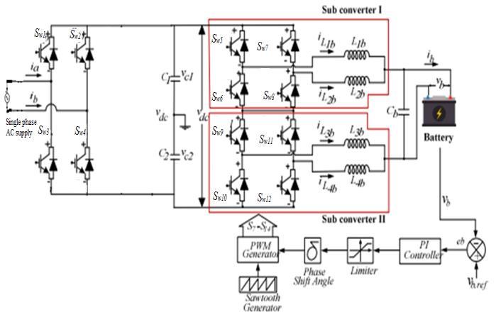
Twopairsofswitches(����5and����8)forsub-converterIand switches(����9and����12)forsub-converterIIareconnectedin parallel.Thisconverterworkswithasingle-controlleranda single-switching frequency due to an adequate control scheme,producingafrequencythatisdoubletheoriginal.All theharmonicfilterinductorsofinterleavedDC-DCconverter are identical. Switches (����5 and ����6) and (����7 and ����8) carrier signals include an 1800 phase shift to remove harmonicsanddcripple.TheEVchargerdrawssinusoidal linecurrentthatisin-phasewithinputvoltage.
PIcontrollersareoftenusedintheorganization,especially when response speed is not always an issue. The P-I controller is used specifically to deal with frequent state errors caused by the P (proportional) controller. This controllerisbasicallyusedinareaswheresystemspeedis notalwaysaproblem.Sincethecontrollerdoesnothavethe ability to reverse future errors of the device, it does not reduce the increase time and does not eliminate the oscillations.
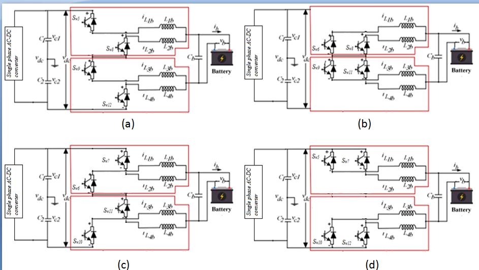
Figure2:modeof
Modeofoperationofsub-converter1isexplainedbelow:
MODE 1- Inthismode,switchesSW5,SW8,SW9 andSW12 are turned ON, the inductors L1b, L4b is charging and the inductors L2b, L3b is discharging The Mode 1 Equivalent CircuitofParallelInterleavedDC-DCConverterisshownin Figure2(a).
MODE2- Inthis mode, switchesSW6, SW8, SW9 andSW11 are turned ON. All the inductors L1b, L2b, L3b and L4b are discharging. The Mode 2 Equivalent Circuit of Parallel InterleavedDC-DCConverterisshowninFigure2(b).
MODE3- The Mode 3 Equivalent Circuit of Parallel InterleavedDC-DCConverterisshowninFigure2(c).With the activation of Switches SW6, SW7, SW10 and SW7, the inductorsL1b,L4b isdischargingandtheinductorsL2b,L3b is charging.
MODE4- The Mode 4 Equivalent Circuit of Parallel InterleavedDC-DCConverterisshowninFigure2(d).Inthis mode,switchesSW5,SW7,SW10andSW12areturnedON.Allthe inductorsL1b,L2b,L3b andL4b arecharging.
TheTwoParallelInterleavedDC-DCConverterdelivers200400VDCforvariousrangesofEVbatterychargingusingan input DC voltage of 760 Volts. Considering the given specificationsfortheconvertershownintable1.
Table1:DesignSpecifications
Thedutyratio,Dfortheproposedconverter,iscalculatedas, D= (1)
International Research Journal of Engineering and Technology (IRJET) e-ISSN: 2395-0056
Volume: 11 Issue: 09 | Sep 2024 www.irjet.net p-ISSN: 2395-0072

D= D=0.263to0.53.
Theaverageoftheinductorcurrentsisprovidedby, IL1=IL2=IL3=IL4= (2)
Where,IL1=IL2=IL3=IL4 =InductorCurrents, Io =OutputCurrent
IL1=IL2=IL3=IL4= =25A
Theinductorripplecurrentisgivenby,

TheInductancevalueiscalculatedfromtheequation, L1b =L2b =L3b =L4b = (4)

Where, =Inductorripplecurrent, =Minimumoutputvoltage, =Switchingfrequency
Table2.DesignParameters

L1b =L2b =L3b =L4b = =4.71mH
The output capacitor is calculated from the following equation, Cb = (5) Cb = C


ThevaluesoftheDClinkcapacitorsC1 andC2 are,
Thesimulationcircuitofsingle-phaseAC-DCconverterfed twoparallelinterleavedDC-DCconverterforEVfastcharging isshowninfigure3.AsinglephaseACsourceof230V,50Hz isprovidedassupplytotheAC/DCconverterwhoseoutputis 760Vand 10KW whichin turn provides supplyto the two parallelinterleavedDC/DCconvertersinordertochargethe batteryof180V,150Ah.

1 ,C2 = (6)
Where, =5%allowablerippleintheDC-linkvoltage, =Rectifierswitchingfrequency =OutputpowerofAC-DCconverter, Vdc =OutputvoltageofAC-DCconverter. C1 ,C2 = C1 ,C2 =346.26μF.

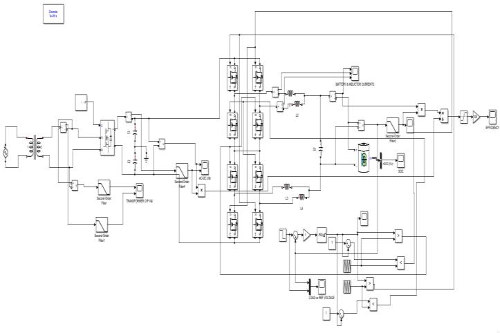
Fig3:SimulationCircuit
Figure 4, shows the output voltage and output current waveformsofthesingle-phaseAC-DCconverter.Theoutput voltageisaround760Vandcurrentisaround14A.
International Research Journal of Engineering and Technology (IRJET) e-ISSN: 2395-0056
Volume: 11 Issue: 09 | Sep 2024 www.irjet.net p-ISSN: 2395-0072
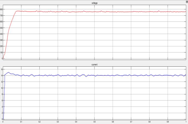
Figure4:OutputVoltageandCurrentofAC/DC Converter
Thereferencevoltageforinterleavedconvertercontrolis initially provided as 400V and changed to 200V at t=0.6s. Figure5,showsthebatteryvoltagecomparedwithreference voltage at different intervals. In this the reference voltage (blueline)isinitiallyof400Vandreducedto200Vatt=0.6s andthemeasuredvoltage(redline)isfollowingthereference voltageinbothconditions.
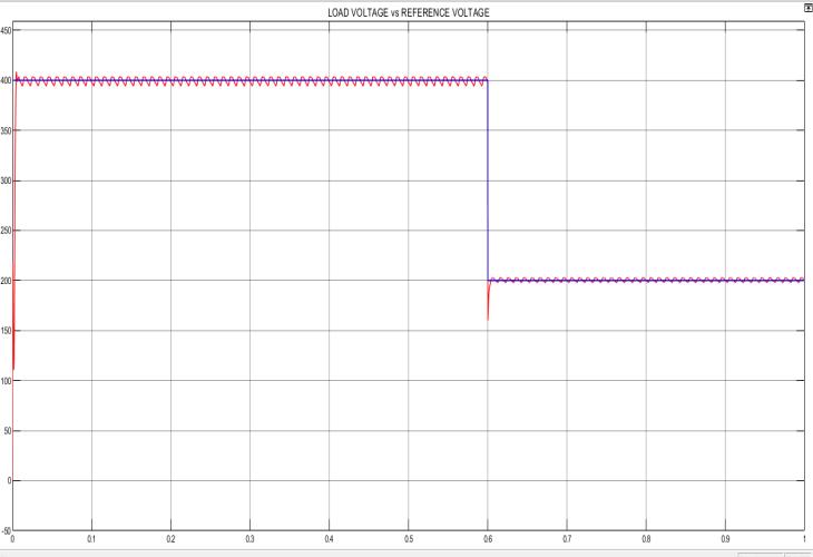
Figure5:TheLoad(Battery)VoltageComparedWith ReferenceVoltageWaveform
Figure 6, shows the batter and inductor current waveforms. The battery current is of 24A initially with inductor currents are shared equally of 12A and at t=0.6s, whenthevoltagereferenceisreducedto200V,thebattery currentisincreasedto40Awithbothinductorssharing20A individually.
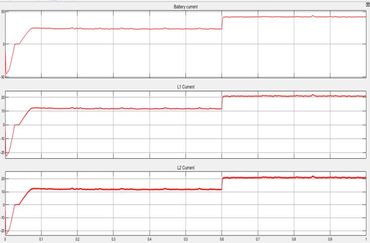
Figure6:TheBatteryCurrentAlongWithInductor CurrentsWaveforms
Figure7,showsthepercentagestateofcharge(SOC)of batterywaveform.The%SOCisincreasingfrom50%asthe batteryischargingandafter t=0.6s, the rate ofchargingis increasedduetoincreaseinconverteroutputcurrent.This provesthatthebatteryischarging.
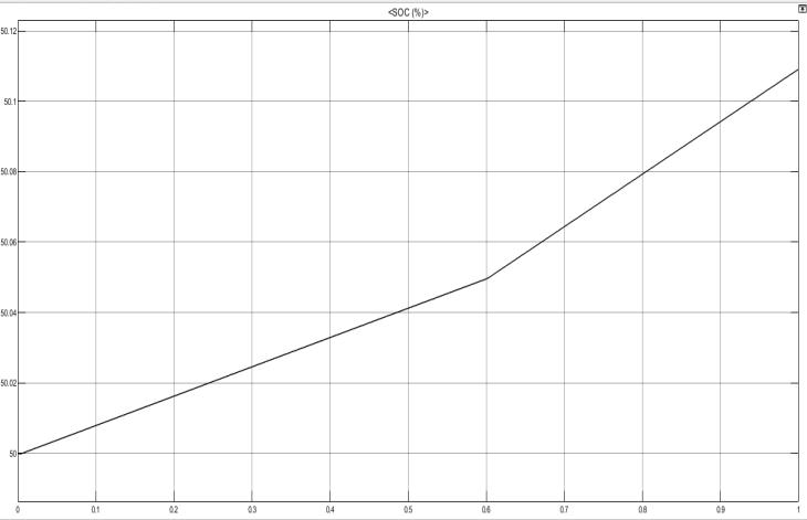
Figure7:The%SOCofTheBatteryWaveforms
Figure 8, shows the total harmonic distortion(THD) obtainedfromfastfouriertransform(FFT)analysisfor400V and 200V respectively. The %THD of the source current when reference voltage is 400V is around 3.27% figure(a) andwhenreferencevoltageis200Visaround3.35%figure (b).
International Research Journal of Engineering and Technology (IRJET) e-ISSN: 2395-0056
Volume: 11 Issue: 09 | Sep 2024 www.irjet.net
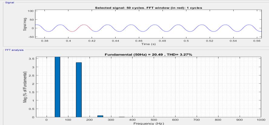
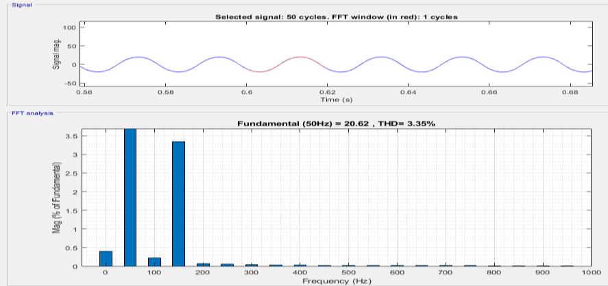
Figure8:The%THDofTheSourceCurrentAt ReferenceVoltageOf(a)400V(b)200V
Table3:ParametersoftheTwoParallelInterleaved CircuitconsideredfortheHardware
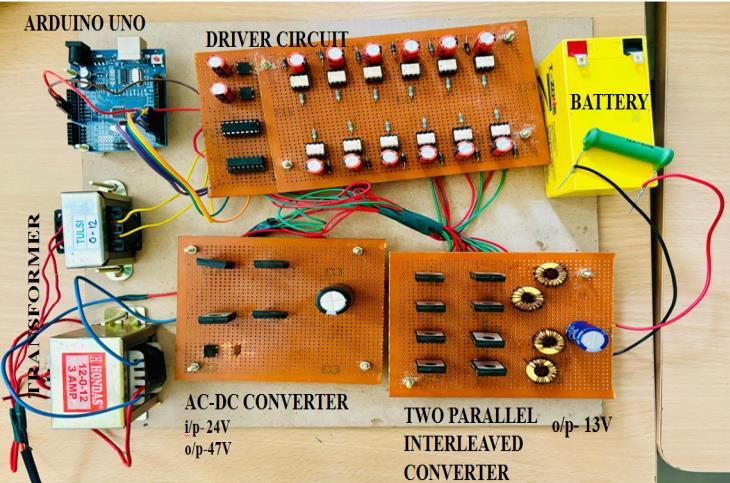
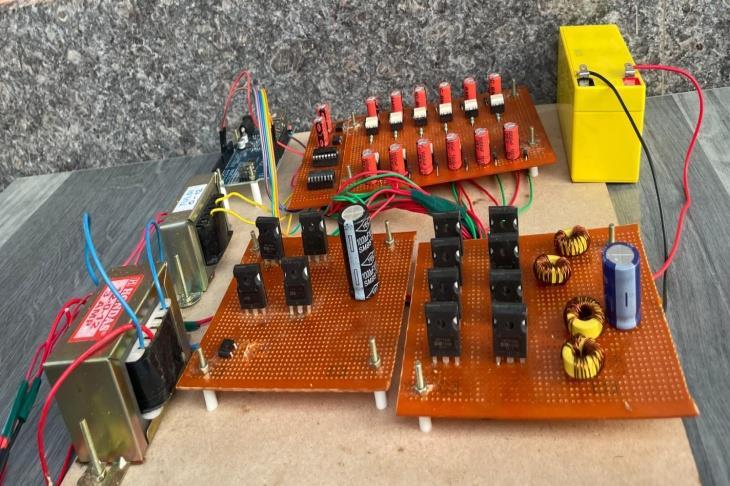
Thehardwarecircuitofthree-phaseAC-DCconverterfedtwo parallelinterleavedDC-DCconverterforEVfastchargingis showninfigure9.SinglephaseinputACsupplyi.e.,230volts, isprovidedto step-downtransformerof230/24V,3A,which isthentotheAC-DCconverter.TheAC-DCconvertergivesan outputvoltageof~47voltswhichisfurtherconnectedtothe two parallel interleaved DC-DC converter. The parallel interleavedDC-DCconverterprovidesanoutputof13voltsto chargethebatteryof12volts,1.3Ahcapacity.
International Research Journal of Engineering and Technology (IRJET) e-ISSN: 2395-0056
Volume: 11 Issue: 09 | Sep 2024 www.irjet.net p-ISSN: 2395-0072
8. HARDWARE RESULTS
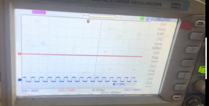
Figure11,showsthegatepulsewaveformgeneratedfromthe driver circuit. The pulse is viewed in the Cathode ray oscilloscope(CRO).
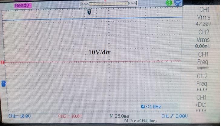
TheinputacvoltageisconvertedtodcvoltageintheACDCconverterisaround48Vwhichisshowninfigure12.
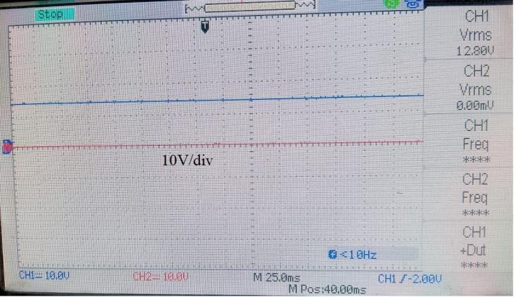
The output voltage of interleaved converter is around 12.8V, which is fed to the battery, to charge the battery. Figure 13, shows the output voltage of the two parallel interleavedDC-DCconverter.
A Two parallel interleaved DC-DC converter for EV fast charging was proposed. In the proposed configuration, a singlephaseACsourceof415V,50Hzisprovidedassupply to the AC/DC converter whose output is 760V and 10KW whichinturnprovidessupplytothetwoparallelinterleaved DC/DC converters in order to charge the battery of 180V, 150Ah.TheTHDfor400Vwasfoundtobe3.27%andTHD for200Vwasfoundtobe3.35%.Thetheoreticalanalysisof this unique design was empirically validated using the MATLABSimulinkplatform.Thehardwarewasimplemented for lower ratings to prove the concept of the proposed converter.AsinglephaseACsupplywasfedtotheproposed systemtochargea12Vbatteryandthehardwareresultsof thesamewereanalysed.
[1] M.A.Hannan,M.M.Hoque,A.Hussain,Y.Yusofand P.J.Ker,”Stateof-the-ArtandEnergyManagement SystemofLithium-IonBat-teriesinElectricVehicle Applications: Issues and Recommendations,” in IEEE Access, vol. 6, pp. 19362-19378, 2018, doi: 10.1109/ACCESS.2018.2817655.
[2] BhimSingh,BrijNSingh,AmbrishChandra,Ashish Pandey, Dwaraka P Kothari, “A Review Of ThreePhaseImprovedPowerQualityAc-DcConverters”, inIEEETransactionsonIntelligentTransportation Systems,vol.22,no.1,pp.9-22,Jan.2021..
[3] T. Saravana kumar, R. Saravana kumar, “ Design, Validation, And Economic Behavior Of A ThreePhase Interleaved Step-Up Dc–Dc Converter For
International Research Journal of Engineering and Technology (IRJET) e-ISSN: 2395-0056
Volume: 11 Issue: 09 | Sep 2024 www.irjet.net p-ISSN: 2395-0072
ElectricVehicleApplication”inIEEEAccess,vol.8, pp. 119271-119286, 2020, doi: 10.1109/ACCESS.2020.3005244.
[4] F.Zhu,G.Liu,C.Tao,K.WangandK.Jiang,”Battery management system for Li-ion battery,” in The JournalofEngineering,vol.2017,no.13,pp.14371440,2017,doi:10.1049/joe.2017.0569.
[5] KaiZhou,YanzeWu,XiaogangWu,YueSun,DaTeng andYangLiu,“ResearchandDevelopmentReview of Power Converter Topologies and Control Technology for Electric Vehicle Fast-Charging Systems”, Electronics 2023, 12, 1581. https://doi.org/10.3390/electronics12071581, MDPI.
[6] R.Deng,Y.Liu,W.ChenandH.Liang,"ASurveyon ElectricBuses-EnergyStorage,PowerManagement, andChargingScheduling,"inIEEETransactionson Intelligent Transportation Systems, vol. 22, no. 1, pp.9-22,Jan.2021.
[7] A. Khaligh and Z.Li, "Battery, Ultracapacitor, Fuel Cell, and Hybrid Energy Storage Systems for Electric, Hybrid Electric, Fuel Cell, and Plug-In HybridElectricVehicles:StateoftheArt,"inIEEE TransactionsonVehicularTechnology,vol.59,no.6, pp.2806-2814,July2010.
[8] I.Husainetal.,"ElectricDriveTechnologyTrends, Challenges, and Opportunities for Future Electric Vehicles,"inProceedingsoftheIEEE,vol.109,no.6, pp.1039-1059,June2021.
[9] M.Dabbaghjamanesh,A.Kavousi-FardandJ.Zhang, "Stochastic Modeling and Integration of Plug-In Hybrid Electric Vehicles in Reconfigurable MicrogridsWithDeepLearning-BasedForecasting," inIEEETransactionsonIntelligentTransportation Systems,vol.22,no.7,pp.4394-4403,July2021.
[10] U.Zafar,S.BayhanandA.Sanfilippo,"HomeEnergy ManagementSystemConcepts,Configurations,and Technologies for the Smart Grid," in IEEE Access, vol. 8, pp. 119271-119286, 2020, doi: 10.1109/ACCESS.2020.3005244.
[11] V.Monteiro,J.G.PintoandJ.L.Afonso,"Operation Modes for the ElectricVehiclein Smart-Gridsand Smart Homes: Present and Proposed Modes," in IEEETransactionsonVehicularTechnology,vol.65, no. 3, pp. 1007-1020, March 2016, doi: 10.1109/TVT.2015.2481005.
[12] M.M.Faruk,N.T.KhanandM.A.Razzak,"Analysis oftheImpactofEVChargingonTHD,PowerFactor and Power Quality of Distribution Grid," 2021
2024, IRJET | Impact Factor value: 8.315 |
Innovations in Power and Advanced Computing Technologies (i-PACT), Kuala Lumpur, Malaysia, 2021, pp. 1-6, doi: 10.1109/iPACT52855.2021.9697024.
[13] S.-J.Huang,B.-G.HuangandF.-S.Pai,"FastCharge Strategy Based on the Characterization and Evaluation of LiFePO4 Batteries," in IEEE Transactions on Power Electronics, vol. 28, no. 4, pp.1555-1562,April2013.
[14] H. Karneddi, D. Ronanki and R. L. Fuentes, "TechnologicalOverviewofOnboardChargersfor Electrified Automotive Transportation," IECON 2021 – 47th Annual Conference of the IEEE IndustrialElectronicsSociety,Toronto,ON,Canada, 2021,pp.1-6.
[15] G. Rajendran, C. A. Vaithilingam, N. Misron, K. Naidu, and M. R. Ahmed, “Voltage oriented controllerbasedviennarectifierforelectricvehicle chargingstations,”IEEEAccess,vol.9,pp.50798–50809,2021.