
International Research Journal of Engineering and Technology (IRJET) e-ISSN: 2395-0056
Volume: 11 Issue: 09 | Sep 2024 www.irjet.net p-ISSN: 2395-0072

International Research Journal of Engineering and Technology (IRJET) e-ISSN: 2395-0056
Volume: 11 Issue: 09 | Sep 2024 www.irjet.net p-ISSN: 2395-0072
Vijay M1 , Vinayagamoorthi M A2
1Student, Department of Mechanical Engineering, Kumaraguru College of Technology, Tamil Nadu, India. 2Assistant Professor II, Department of Mechanical Engineering, Kumaraguru College of Technology, Tamil Nadu, India.
Abstract - This paper is focused on the design, optimization,andanalysisofsteeringcomponentsandthe "Designofsteeringgeometryforformulastudentcars.The main objective of the research is to ensure more rational and effective steering input or response between the driver and the wheels, reducing the amount of work the driver must do and enhancing their engagement with the wheels. The focus on the project is to consider the Ackermanset-up,steeringeffort,steeringarmlength,rack motion, turning radius, steering ratio, slip angle, castor, toe angles, kin-pin angle, and camber angle in order to obtainthatsensitivity.RackandPinionserveasthelinkin thisinstancebetweenthedriverandwheels.Theoptimum tie-rod length 260.08mm is obtained by simulation to reduce the slip angle during cornering and the overall turningradiusofthevehicleisreducedto3.5metres.
Key Words: Steering, Ackerman, Rack and Pinion, Optimization.
TheSteeringsystemisthecontrollingsystemofa vehicle. TheAckermanngeometry,Anti-Ackermanngeometry,and parallelsteeringtypegeometryarejustafewexamplesof thenumeroussteeringgeometriesthatareusedinvarious kindsofcars.Eachofthese geometrieshasauniquesetof benefits, so geometry must be chosen based on the workingcircumstances[1].Sincethecarisarigidbody,all of the tyres must turn around the same center to allow it to turn; otherwise, the tyres will push or pull against one another by forcing the tyres to move away from the intended path, this push or pull impact will cause a scrub andcause the cartolose momentum. Toprevent thisand assist the car in following the pattern, the steering mechanisms are employed depending on the application becauseeachtechniquehasadvantagesanddisadvantages [2]. The Ackerman systems varies depending on how much the tires scrub. (i.e., produced by each mechanism whilethecaristakingaturn).Whilethescrubeffectdoes not exist in the Ackerman system, it grows in parallel processes and intensifies in anti-Ackerman systems. Additionally, the tire characteristics, turn radius, turn speed, and road conditions all influence the optimal steeringanglerequiredforaturn.Thecarencountersboth
high-speed and low-speed bends, therefore an ideal steeringsystemisnotconceivablewithoutuniquesteering anglecontrolforeachwheel.Ackermansteeringgeometry is selected due to its high maneuverability capability and effective turnings in slow speed cornering. Hence optimization and development of steering geometry and components are the important stages in the development of an effective steering system. In Ackerman steering geometrytheinnerwheelturningangleishigherthanthe outerwheelturningangle.Mostmoderncars,smalltrucks, andSUVshavearackandpinionsteeringmechanism.This transformsthesteeringwheel'srotationalmotionintothe linearmotionthatturnsthewheelsanddirectsyourroute. Asteeringpinion,acirculargear,isusedinthemechanism to lock teeth on a bar (the rack). Additionally, it converts large steering wheel rotations into small, precise wheel rotations, giving the steering a direct and firm sensation. Formula (FSAE) car steering systems are designed and manufactured based on the rules specified in the rule books. Trapezoidal arrangement of the steering components to achieve the steering geometry helps to develop a compact layout and reduces the space required forthesteeringpackage.Optimizingthetierodsimproves thevehicle'scorneringabilitybyreducingtheslipangleof the wheels. The lateral force displacement vs slip angle graph is obtained, and the optimum tie rod length will be designed and implemented in the vehicle. Steering geometry is calculated and modeled to achieve 100% Ackermanngeometryandtheturningradiusofthevehicle is reduced for the sharp cornering that improves the overallabilityofthevehicle.
A fundamental step for modelling and creating a steering systemisdemonstratedinthecurrentstudy.Theaimisto design a steering system with the desired steering ratio, zero play. DS SolidWorks is used for the design process, andAnsysisusedforthefiniteelementanalysis.Therack andpinionandsteeringshafts,whichareprimarilycaused bythelongitudinalandlateralaccelerationsthatactonthe driverandthecar,aswell asthefactthatthedrivermust applyaforcemuchgreaterthanthattocontrolthevehicle, allneedtobedesignedwiththevariousimpactforcesand stressesinmind.[1]
International Research Journal of Engineering and Technology (IRJET) e-ISSN: 2395-0056
Volume: 11 Issue: 09 | Sep 2024 www.irjet.net p-ISSN: 2395-0072
Inthis article differentsteering geometry and parameters are compared for choosing a steering system. To design andsupportthechosenpolicies,theresearchmakesuseof the RMS error tool, turning radius estimation, steering effort calculation, and understanding of Ackerman and trapezoidal systems. The process includes a step-by-step design flow for a variable Ackerman steering geometry andacollectionofMATLABalgorithmsneededtocalculate turning radius, space, angles on inner and outer wheels, andnumerousothercharacteristics.[2]
The study was conducted to assure the most effective steeringassemblyselection foranAll-TerrainVehicle.For an appropriate choice of steering system, numerous parameters are taken into consideration throughout this procedure. Along with using Ackerman geometry for the steering component, the steering system includes a rack andpiniongearbox.TheTieRodslinktheRackandPinion gearboxtothesteeringarm.Theloadbearingcapacitiesof tierodsandsteeringarmsaredesignedandexamined[3]
Designing and improving the Anti-Ackerman steering system is the primary goal of the work. The goal was to create a steering system that would respond quickly during fast turns. To close the gap between the driver's steering input and the direction of movement of the wheels, the setup incorporates an outer wheel steering anglethatisgreaterthantheinnerwheel.SolidWorkswas usedforthedesignandoptimization,whichconsideredall steeringfactors.LotusSharkwasusedfortesting.[4]
This paper's major goal is to examine the FSAE car's optimized steering system design, which offers the driver good steering response and easy handling with increased stabilityatgreaterspeeds.[5]
In the current work, a novel mathematical model is created to design the steering geometry taking various geometry parameters into consideration. Three equations make up this mathematical model. By resolving these equations, we may obtain various steering geometry parameterstodeterminethebeststeeringgeometry.This modelmaybeappliedtofrontandrearsteeringdesignsto provide two-wheel steering as well as four-wheel steering.[6]
In this study, a novel mathematical model is created to design the steering geometry taking various steering parameters into consideration. The equations in this mathematical model are organised according to the calculation parameters. This equation can be solved to obtain various steering parameters, considering the ideal steering geometry in relation to steering effort and Ackermann.[7]
The major goal of this research is to create a steering system that can counter bump and roll steer and
guarantee adequate reaction to turns made at both high andlowspeeds.
The steering settings and geometry are first determined, and then the lotus shark suspension analyser is used to analyse the results. After geometry optimisation and analysis, SolidWorks is used to design the entire system.[8]
This article considers all possible stresses, strains, and other mechanical qualities that could affect the steering system.Themaingoalofthesteeringsystemistogivethe driver a strong steering reaction and the ability to continuously adjust the path of the vehicle. The design, production, and calibration of the steering system are the main topics of this paper. To improve handling and boost stabilityathighspeeds,thesystem'sweightwasprimarily reduced,alongwiththeamountoffreeplayatthesteering wheel.[9]
Many of today's cars use a two-wheel steering system when we check them out. The drawback of two-wheel steering is that a larger turning radius is needed to turn the vehicle. But if we consider efficiency, we find that a two-wheel steering system is less effective than a fourwheel steering system. Therefore, by switching to a fourwheel steering system from a two-wheel steering system, wecanincreaseefficiencyandreducetheturningradiusof the vehicle. The only solution for oversteering and understeeringisafour-wheelsteeringsystem.Thegoalof this project is to concurrently move all four wheels. For the vehicle's steering system, we employ the Ackerman systematboththefrontandrearwheels.[10]
Totransformrotationintolinearmotion,rackand piniongearsareused.
Thegeariscalledthepinion,andtheflat, toothed componentiscalledtherack.
Therearetwogearsinarackandpiniongearset.
The rack may be straight or flat, and the pinion gearisatypicalroundgear.
The rack's teeth and the pinion gear's teeth fit togetherperfectly.
Universaljoint,commonlyreferredtoasaU-joint, is a kind of mechanical connection that enables two shafts to be coupled and transmit torque whilestillbeingabletofreelyrotateandtravelin separatedirections.
When the relative orientation of the two shafts mayalter,thisishelpful.
International Research Journal of Engineering and Technology (IRJET) e-ISSN: 2395-0056
Volume: 11 Issue: 09 | Sep 2024 www.irjet.net p-ISSN: 2395-0072
3.3. Shaft:
A shaft is a rotating machine part that transfers energy from one part to another or from a machine that produces energy to a machine that consumesenergy.
Shaftsaretypicallycircularincross-section.
3.4. Quick release:
The rapid demounting tool has a straightforward design and transfers torque through involute splines.
3.5. Tie rod:
When the steering wheel is turned, the front wheels pivot on the steering knuckles, which are connectedtothesteeringrackateitherendbytie rods.
The tie rod includes two threaded portions that can be adjusted in length to align the front wheels.
3.6. Steering arm:
The steering arm is used to connect the tie rod withtheuprightofthewheel.
4. PROBLEMS FACED
Length of the tie rod plays the critical role in the steering system, improper tie rod length causes toe-in and toe-out of the wheels that causes wear of tires, bump steer of the vehicle,vibrationonthesteeringwheel.
5. SOLUTION CONCEPT
Based on the assumed values for the basic dimension of the wheel track and wheelbase of the vehicle, a geometry is drawn on the solid works software and the Ackerman angle is found. Then the model is simulated on the Lotus Sharksoftwaretofindtheexacttierodlength.
6. METHODOLOGY
i. Problemselection.
ii. Solutionconcept.
iii. Designobjectives.
iv. SimulationandValidation.
v. Materialselection.
vi. Analysis.
vii. Manufacturingandimplementation
Selected parameters:
Wheelbase 1550mm
FrontTrackwidth 1200mm
RearTrackwidth 1140mm
Steering Ratio:
The ratio of steering wheel turn angle with respect to the maximumturningangleoffrontwheel.
S.R=104.5/38 =2.75
Rack Travel:
The amount of rack travel with respect to the steering rationeedstobefixed.
Thesteeringwheelradiusis115mm.
Foronecompleterotationthesteeringwheeltravel
=2πxr
=0.691m
At one complete rotation of steering wheel the maximum rack travel is reached with respect to the maximum steer angle.
Steeringratio=Steeringwheeltravel/Racktravel.
2.75=0.691/Racktravel
Racktravel=251mm
Requiredracktravelis251mm.
Research
Volume: 11 Issue: 09 | Sep 2024 www.irjet.net p-ISSN: 2395-0072

Thetopviewofthesimulatedvaluesinlotusshark software.
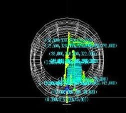

Table.1. Coordinates
Volume: 11 Issue: 09 | Sep 2024 www.irjet.net
Table.2. Toeangle,Kingpinangle,Damperratio,and SpringratiowithrespecttoBumptravel.
Table.3. Dampertravel,springtravelwithrespectto bumptravel.
Considering the data derived from the Lotus Shark software, crucial parameters include a Kingpin angle measuring4degrees,aCastoranglesetat3.5degrees,and aCamberanglereading-2degrees(wherethe"-"denotes negativecaster).Tocounteractundesirablefluctuationsin wheel camber during steering maneuvers, it is recommended to align the kingpin inclination as close to verticalasfeasible.Hence,akingpinangleof3.5degreesis chosen to meet this objective effectively. Utilizing Ackermann geometry featuring an Ackermann angle of 19.22degrees,thetie-rodlengthismeticulouslyoptimized to 260.08mm via simulation methods. This fine-tuning serves to minimize slip angle during cornering, consequently yielding a noteworthy reduction in the vehicle's overall turning radius, down to 3.5 meters. Such precise adjustments are instrumental in enhancing the vehicle's handling dynamics, steering responsiveness, and overall performance, ensuring an optimal driving experienceacrossvariousroadconditionsandmaneuvers.

International Research Journal of Engineering and Technology (IRJET) e-ISSN: 2395-0056
Volume: 11 Issue: 09 | Sep 2024 www.irjet.net p-ISSN: 2395-0072

Fig.5. CADModel
Steering wheel
Manufacturing process Waterjet
Material Aluminium-7075-T6
No 1

Fig.6. SteeringWheel
Quick release mechanism
Material Aluminum7075-T
Manufacturing process OEM No 1

Fig.7. QuickReleaseMechanism
Steering spline
Material En-8
Manufacturing process OEM No 1

Fig.8. Steeringspline
Universal joint
Material Alloysteel Manufacturing process OEM No 1

Fig.9. Universaljoint
International Research Journal of Engineering and Technology (IRJET) e-ISSN: 2395-0056
Volume: 11 Issue: 09 | Sep 2024 www.irjet.net p-ISSN: 2395-0072
Steering column
Material En-8rod
Manufacturing process Latheanddrilling
No 1

Fig.10. Steeringcolumn
Steering column and pinion coupling
Material Mild steel (AISI1020) rod
Manufacturing process Latheanddrilling
No 1

Fig.11. Steeringcolumnandpinioncouple
Rack and Pinion:
Manufacturing Custom manufacturing No 1

Fig.12. RackandPinion
Tie rod:
Material Mild steel rod (AISI1020)
No 2

Fig.13. Tierod.
Steering arm:
Material Mildsteelsheet-3mm
Manufacturing process Lasercutting No 4

Fig.14. Steeringarm
FINAL STEERING ASSEMBLY IN VEHICLE

[1] Anti-Ackermann Steering System of Formula Student carAdvaitDeshmukh,GouriTawhare,ShreyashKochat.
[2] Designing Variable Ackerman Steering Geometry for FormulaStudentRaceCar,PuneetGautam,PrajwalSanjay Agraw, Shubham Sahai, Sachin Sunil Kelkar, Mallikarjuna ReddyD
International Research Journal of Engineering and Technology (IRJET) e-ISSN: 2395-0056
Volume: 11 Issue: 09 | Sep 2024 www.irjet.net p-ISSN: 2395-0072
[3]DesignMethodologyofSteeringSystemforAll-Terrain vehicles. Dr.V.K.Saini, Prof.Sunil Kumar, Amit Kumar Shakya,HarshitMishra
[4] Design and Optimization of Anti-Ackerman Steering. VijayMistry,VipulAwatade
[5] Design of Steering System of FSAE Car. Abhishek SubhashBhujbal
[6] Mathematical Model to Design Rack and Pinion AckermanSteeringGeomentry.DipalkumarKoladia.
[7]MathematicalStudyandDesignofAckermannSteering Geomentry in Four-Wheeler. Mr. Varad Sanjay Kumbhar, Mr.MangeshVijaykumarMaliz,Mr.NitinParasramBanne
[8] Design and Optimization of the Steering System of a Formula SAE Car Using Solidworks and Lotus Shark. Sadjyot Biswa, Aravind Prasanth, M S Dhiraj Sakhamuri andShauryaSelhi.
[9]ShreeyashUddhavJadhav,SurajRamuGowda.
[10]FourWheelSteeringSystem.AlamShadab,DubeyS.K, SinghS.K,DixitRaja,PanditArvindaK.