
International Research Journal of Engineering and Technology (IRJET) e-ISSN: 2395-0056
Volume: 11 Issue: 09 | Sep 2024 www.irjet.net p-ISSN: 2395-0072

International Research Journal of Engineering and Technology (IRJET) e-ISSN: 2395-0056
Volume: 11 Issue: 09 | Sep 2024 www.irjet.net p-ISSN: 2395-0072
R RAKSHITH1 , Dr. HEMALATHA J N2 , Dr. MADHU B R3
1Student, EEE Dept., RV College of Engineering, Bengaluru, India
2 Associate Professor, EEE Dept., RV College of Engineering, Bengaluru, India
3 Assistant Professor, EEE Dept., RV College of Engineering, Bengaluru, India
Abstract - This paper work is aimed at design and simulation analysis of two-stage grid connected photovoltaic(PV) system using SEPIC converter and modifiedH-Bridgemultilevelinverter.Thefirststagehas aCoupledInductorbasedSingleEndedPrimaryInductor Converter(SEPIC) with Incremental Conductance Maximum Power Point Tracking(MPPT) algorithm that aid in tracking the Maximum Power Point of the PV system with high tracking speed and output efficiency. The second stage is a modified three phase H-Bridge Multilevel Inverter controlled by second order generalized integral (SOGI) technique for pumping the sinusoidal and less distorted power extracted from PV into the distribution grid. The modeling of proposed systemwascarriedoutonthePVmoduleoftotalcapacity of 2100Wtoobtain improved efficient power extraction.
Key Words: SEPIC Converter, DC-DC Converter, DC-AC Converter, H-Bridge Multilevel Inverter, Maximum Power Point Tracking, Total harmonic distortion, Photo Voltaic, Matlab, Simulink
In recent days the use of renewable energy is widely increasing day by day. Among them, Solar Energy is considered as one of the important energy sources since these are environmental friendly and produces electric power without causing pollution. Therefore, Solar Photo Voltaic(PV)panelsarepreferredthatarereadilyavailable. ThePVsystemisstationary,silent,freeofmechanicalparts, andhaslowrunningandmanufacturingcostscomparedto other renewable resources. The use of photovoltaic as a sourceofelectricalenergyshowsagrowingtrendbothinthe implementationoftheglobalsectorandintheperformance ofvariousindustrialplants.Thistrendismotivatedbymany factors, such as decrease in the cost of producing photovoltaic electricity per kW and the rise in fossil fuel pricesandthedevelopmentofeffectivephotovoltaicenergy conversiontechnology[1-4].
Thephotovoltaiccellsgenerateelectricalenergyusingthe sunlight.APVpanelisformedofPVcellsconnectedinseries, parallelorseries-parallelthatisworkingcommonlywitha DC-DC converter and stores electrical energy in a battery array.Inothersituations,aDC-ACinverterisusedtoconnect
thePVpanelandDC-DCconverterinordertoaddelectricity tothegrid.Whenitcomestoinverters,multilevelinverters (MLIs) and two level inverters are typically utilized [5]. Comparing MLI to two-level inverters, the former is more appealingduetolowerswitchingstresses,loweroperating frequency,andsmallerfilterrequirements.Therehavebeen reportsofseveralenhancedtopologieswithsmallerfilters, more stages, less Total Harmonic Distortion (THD), and fewerswitches.Inthisoperation,theDC-DCconvertermust runatitsMaximumPowerPoint(MPP)inordertoincrease the generating efficiency. Therefore, tracking this point requiresanalgorithm.TheMPPTalgorithmisappliedtofind the maximum point that adjusts the duty cycle of the convertertoincreasethegenerationefficiency[8].
Generally,thesystemthatareconnectedtothegridareof twostages,thefirststageisDC-to-DCconvertersthatboosts thePVvoltagesandextracttheMaximumPowerbyutilizing MPPT and the stage two is to invert this DC power to AC power. The Maximum Power Point Tracking (MPPT) algorithm is used to track the maximum power the solar array. The second order generalized integral (SOGI) techniqueisusedtocontrol themultilevel inverter.Inthe proposedsystemitreducescomplexity,lessweight,lowcost, high efficiency, and sinusoidal current is injected into the grid[7].
Figure1depictsthemethodologyoftheproposedsystem.It consistsofdual-stageconversion:aDC-DCconversionstage and a DC-AC conversion stage. DC-DC converter ie., Single InputMultipleOutputSEPICConverter,consistsof anactive switch(��m),twodiodes(D1, D2),inputinductorandcapacitor (Cb, Lm)coupledtotwosplitcapacitors(��1��������2),connected toaDClink.TheinputtotheSIMO-SEPICConverterisgiven fromthePVpanelthatgeneratesDCcurrentfromthesun’s rays. The SEPIC Converter regulatesand boosts up theDC outputvoltagetosuitablelevelsandfeedsittotheproposed H-BridgeMultilevelInverter.TheSIMO-SEPICConverteris controlledbyIncrementalConductanceMPPTAlgorithm.
The modified H-Bridge multilevel inverter consists of 6 activeswitches(S1, S2, S3, S4, S5, S6),theinputtotheinverter is given from the SEPIC Converter, here the multilevel inverter converts DC to 5-Level AC. The switches of the
International Research Journal of Engineering and Technology (IRJET) e-ISSN: 2395-0056
Volume: 11 Issue: 09 | Sep 2024 www.irjet.net p-ISSN: 2395-0072
multilevel inverter is controlled and regulated by second order generalised integral (SOGI) technique using PLL technique.Theoutputofthemultilevelinverterisfedtothe loadandthedistributiongrid.
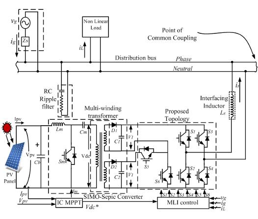
Figure1:CircuitSchemeoftheProposedSystem
3. MODE OF OPERATION OF H- BRIDGE MULTILEVEL INVERTER
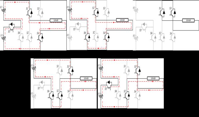
Figure2:ModeofOperation
Mode of operation of H-Bridge Multilevel Inverter is explainedbelow:
Table 2.2,showstheswitchingstatesfordifferentvoltage levels.
MODE 1- Switches S1, S4 and S5 areturnedON.Theoutput voltage value is 2V1. The switches S2, S3, S6 are off. The equivalentcircuitisshowninFigure2(a)
MODE 2- Switches S1, S4 and S6 areturnedON.Theoutput voltage value is V1. The switches S2, S3, S5 are off. The equivalentcircuitisshowninFigure2(b)
MODE 3- Switches S1 and S3 are turned ON. The output voltage value is zero. The switches S2, S4,S5, S6 are off. The equivalentcircuitisshownFigure2(c).
MODE 4- Switches S2, S3 and S6 areturnedON.Theoutput voltage value is −V1. The switches S1, S4,S5 are off. The equivalentcircuitisshowninFigure2(d)
MODE 5- Switches S2, S3and S5areturnedON.Theoutput voltage value is 2V1. The switches S1, S4, S6 are off. The equivalentcircuitisshowninFigure2(e)
Table1:SwitchingStatesforDifferentVoltageLevels
TheINCMPPTapproachisbasedonthefactthat,theslope oftheP-VcurveiszeroattheMPP,positivetotheleftofthe MPP,and negative to the rightof theMPP.INCconditions thatareexpressedinEquations.1,2,3


The INCMPPTmethodhas theadvantage of beingable to computeanddeterminetheexactperturbationdirectionfor theoperatingvoltageofPVmodulesthatissuperiortothe othertwoHCandP&Oalgorithms.
IftheMPPisdeterminedusingtheINCmethod'sjudgment conditions (dI/dV = I/V and dI = 0), it can theoretically prevent the perturbation phenomenon that occurs at the maximumpowerpointthatoccurintheotherMPPTlogics. After that, the operating voltages are set. During experimental experiments, however, it appears that the perturbationphenomenaarestilloccurringaroundtheMPP under non-uniform weather circumstances. Because the likelihoodofsatisfyingconditiondI/dV=I/Visextremely low,and thedeterministicprocessoftheINCalgorithm is more sophisticated, the simulation time spent on INC
International Research Journal of Engineering and Technology (IRJET) e-ISSN: 2395-0056
Volume: 11 Issue: 09 | Sep 2024 www.irjet.net p-ISSN: 2395-0072
algorithm is much longer than compared to HC and P&O methods.
The MPP is tracked by seeking the peak of the P-V curve using the incremental conductance technique that detects theslopeoftheP-Vcurve.Theinstantaneousconductance I/V and incremental conductance dI/dV are used in this MPPTalgorithm.ThelocationofthePVmodule'soperating point in the P-V curve is determined based on the relationship between the two values, as expressed in equations1,2,3,ie.,(1)indicatesthePmoduleoperatesat the MPP, whereas (2) and (3) indicate the PV module operates on the left and right sides of the MPP in the P-V curve,respectively.
TheTable2givestheinformationabouttheinputandoutput parameters required for the design of the Two Parallel InterleavedDC-DCConverter.
Table2:DesignSpecifications PV Array
Module ApolloSolarEnergy ASEC-300G6M (Polycrystalline Module)
Thedutyratio,Disprovidedbythefollowingrelation(VFWD =0):

Where,VOUT=OutputVoltage
VIN=InputVoltage
VFWD=ForwardDiodeVoltage


Theaverageofinputsideinductorcurrentisprovidedinthe followingequation:

Where,IOUT=OutputCurrent


The switching time period, Ts is calculated from the switchingfrequencyasshownbelow:

Where,FS=SwitchingFrequency


Theinputsideinductanceiscalculatedfromtheequation below: (7)


The SEPIC Converter delivers 320 V DC to the multilevel inverterusinganinputDCvoltageof250Volts.Considering thegivenspecificationsfortheconvertershownintable4.1.
Theinductancevalueabovecalculatedistermedascritical inductance.Toensurethattheproposedconverteroperates in CCM under any load conditions, we must use larger inductorsthanthatofcalculatedvalues.
International Research Journal of Engineering and Technology (IRJET) e-ISSN: 2395-0056
Volume: 11 Issue: 09 | Sep 2024 www.irjet.net p-ISSN: 2395-0072
Therippleinductorcurrentsaretakenas20%oftheactual inductorcurrentvaluesforbothintermediateandinputside inductances.
Theintermediateinductancevaluecanbecalculatedusing thefollowingequation:


The coupling capacitor is calculated from the following equation:


The ripple voltage of coupling capacitor (ΔVcb) is taken as 1%oftheactualcouplingcapacitorvoltage(Vcb).
The output capacitor is calculated from the following equation:


Theripplevoltageofoutputcapacitor(ΔVco)istakenas1% oftheactualoutputcapacitorvoltage(Vco).
Table3:SEPICConverterDesignParameters
The simulation circuit of H-bridge multi-level inverter for gridintegrationisshowninfigure3.APVmoduleof250V, 2KW is connected to SEPIC converter integrated 5-level inverterinordertosupplytheloadof1KVAaswellasgridof 50Hz. INC algorithm is used as MPPT in order to extract maximumpowerfromPVmodule.
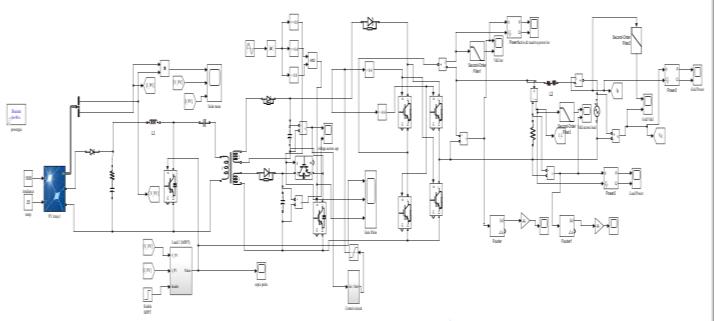
Fig3:SimulationCircuit
Figure 4, shows PV arrays power, voltage and current waveforms.ThePowergeneratedisaround2100Wandthe voltageandcurrentisaround248.5and8.3Arespectively.
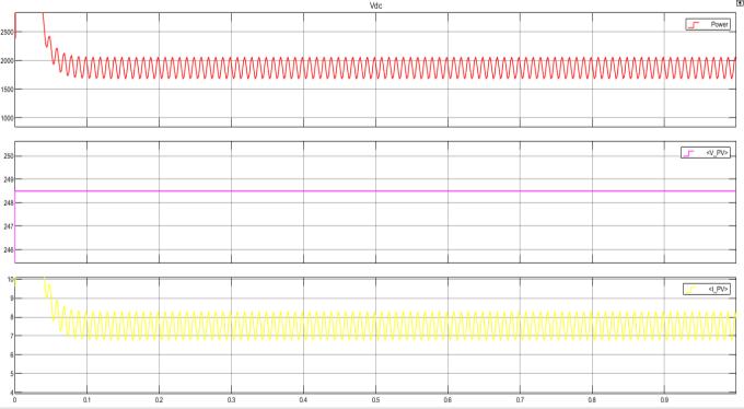
Figure4:Power,Voltage,CurrentWaveformsofPV Array
Figure 5, shows the output-voltage and output-current waveformsoftheH-BridgeMultilevelInverter.Theoutput voltageisaround300Vandcurrentisaround7A
International Research Journal of Engineering and Technology (IRJET) e-ISSN: 2395-0056
Volume: 11 Issue: 09 | Sep 2024 www.irjet.net p-ISSN: 2395-0072
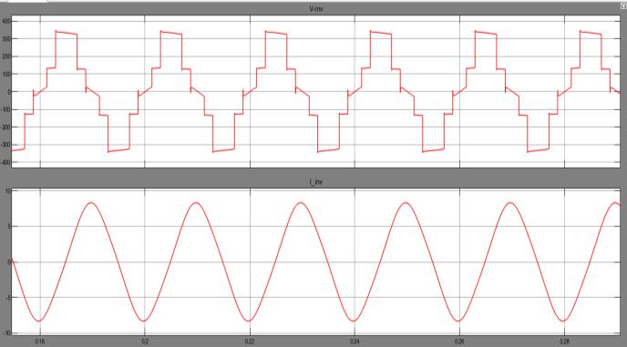
Figure5:InverterVoltageandCurrentWaveforms
The active power measured of the inverter is found to be around1700Wandthereactivepowerisaround0.7.Figure 6, shows the active and reactive power waveforms of inverter.
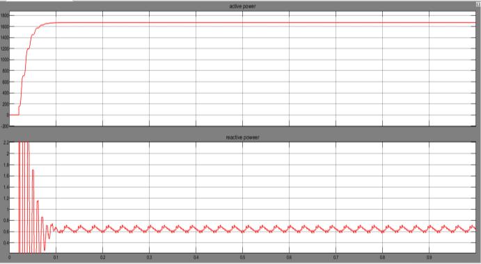
Figure6:InverterPowerWaveforms
Figure 7, shows the current and voltage waveforms of the grid.Voltageo230Voltsandcurrentof1.3Aisobservedfrom thewaveforms.
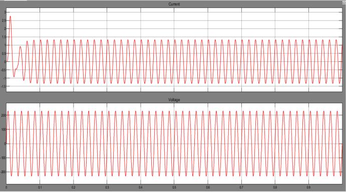
Figure7:GridCurrentandVoltageWaveforms
Figure8,showsgridsactiveandreactivepowerwaveforms. Theremainingpowerafterbeingconsumedbytheloadof 1KVA is being injected to the distribution grid, the active powerisaround450VA.
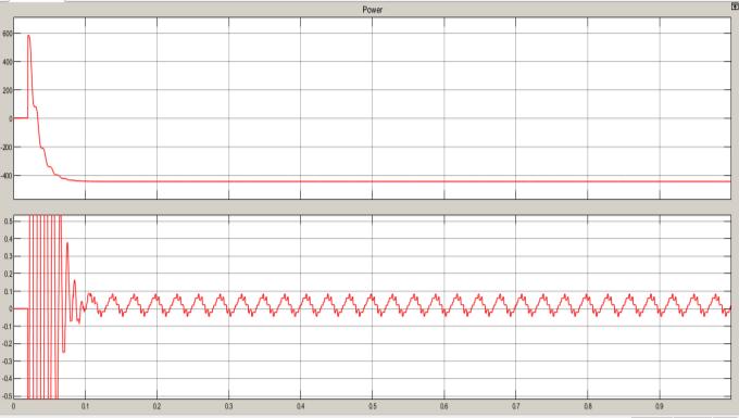
Figure8:GridPowerWaveforms
Figures 9 load current and voltage waveforms the load current voltage observed is around 300 Volts and current is around 5 Amps.
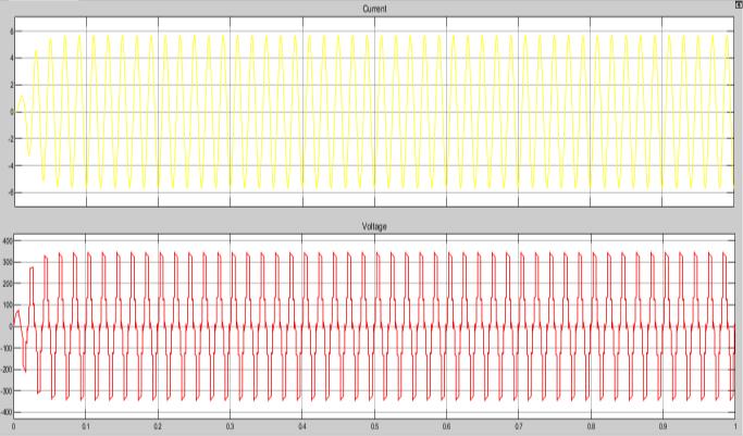
Figure9:LoadCurrentandVoltageWaveforms
Thetotalharmonicdistortion(THD)fortheproposedcircuit is found to be around 4.73%. Figure 10, shows the THD analysis.
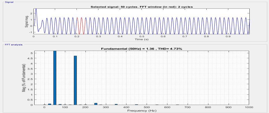
Figure10:THDAnalysis
7. CONCLUSION
Agrid-connectedsolarpowerconversionsystemconsisting offivelevels,utilizinginverters,wassuggested.Utilizingthe fewestpossiblecomponentsforthefive-leveloutput,thenew
International Research Journal of Engineering and Technology (IRJET) e-ISSN: 2395-0056
Volume: 11 Issue: 09 | Sep 2024 www.irjet.net p-ISSN: 2395-0072
topologyisamodifiedH-bridgedesign.OperationoftheICbased MPPT maximizes the power extraction from the PV panels.Atheoreticalderivationandexperimentalvalidation are made about the efficient operation of the proposed Hbridgemultilevelinverter.Atroughly4.74%,theTHD.Italso feedsbackintothegridthePVpowerthatremainsafterload power demand. Further improvements of the system are possiblebyusingadvancedMPPTalgorithmssuchasFirefly, Most Valuable Player algorithm, etc for partial shading conditions.
[1] S. K. Chattopadhyay and C. Chakraborty, ‘‘Fullbridge converter with naturally balanced modular cascaded H-bridge waveshapers for offshore HVDC transmission,’’IEEETrans.Sustain.Energy,vol.11,no. 1, pp. 271–281, Jan. 2020, doi: 10.1109/TSTE.2018.2890575.
[2] A. Ahmed, M. S. Manoharan, and J.-H. Park, ‘‘An efficient single-sourced asymmetrical cascaded multilevel inverter with reduced leakage current suitable for single-stage PV systems,’’ IEEE Trans. EnergyConvers.,vol.34,no.1,pp.211–220,Mar.2019, doi:10.1109/TEC.2018.2874076.
[3] X.Huang,K.Wang,B.Fan,Q.Yang,G.Li,D.Xie,and M. L. Crow, ‘‘Robust current control of grid-tied invertersforrenewableenergyintegrationundernonidealgridconditions,’’IEEETrans.Sustain.Energy,vol. 11, no. 1, pp. 477–488, Jan. 2020, doi: 10.1109/TSTE.2019.2895601.
[4] G.Zhang,Z.Tian,P.Tricoli,S.Hillmansen,Y.Wang, and Z. Liu, ‘‘Inverter operating characteristics optimization for DC traction power supply systems,’’ IEEETrans.Veh.Technol.,vol.68,no.4,pp.3400–3410, Apr.2019,doi:10.1109/TVT.2019.2899165.
[5] A. Kersten, O. Theliander, E. A. Grunditz, T. Thiringer, and M. Bongiorno, ‘‘Battery loss and stress mitigationinacascadedHbridgemultilevelinverterfor vehicletractionapplicationsbyfiltercapacitors,’’IEEE Trans.Transport.Electrific.,vol.5,no.3,pp.659–671, Sep.2019,doi:10.1109/TTE.2019.2921852
[6] C. Liu, N. Gao, X. Cai, and R. Li, ‘‘Differentiation powercontrolofmodulesinsecond-lifebatteryenergy storagesystembasedoncascadedH-bridgeconverter,’’ IEEE Trans. Power Electron., vol. 35, no. 6, pp. 6609–6624,Jun.2020,doi:10.1109/TPEL.2019.2954577.
[7] S. Murshid and B. Singh, ‘‘Analysis and control of weakgridinterfacedautonomoussolarwaterpumping system for industrial and commercial applications,’’ IEEE Trans. Ind. Appl., vol. 55, no. 6, pp. 7207–7218, Nov.2019,doi:10.1109/TIA.2019.2939705.
[8] P. Omer, J. Kumar, and B. S. Surjan, ‘‘A review on reduced switch count multilevel inverter topologies,’’ IEEE Access, vol. 8, pp. 22281–22302, Jan. 2020, doi: 10.1109/ACCESS.2020.2969551.
[9] J.Ma,X.Wang,F.Blaabjerg,W.Song,S.Wang,andT. Liu, ‘‘Realtime calculation method for single-phase cascaded H-bridge inverters based on phase-shifted carrier pulsewidth modulation,’’ IEEE Trans. Power Electron., vol. 35, no. 1, pp. 977–987, Jan. 2020, doi: 10.1109/TPEL.2019.2911422.
[10] J.Ma,X.Wang,F.Blaabjerg,W.Song,S.Wang,andT. Liu, ‘‘Multisampling method for single-phase gridconnected cascaded H-bridge inverters,’’ IEEE Trans. Ind.Electron.,vol.67,no.10,pp.8322–8334,Oct.2020, doi:10.1109/TIE.2019.2947864.
[11] Nirmal Mukundan C M, Vineeth K, Sooraj Suresh Kumar,JayaprakashP,“ImprovedH-bridgeMultilevel Inverter for Grid Integration of Photovoltaic Power ConversionSystemwithPowerQualityEnhancement”, 2020, IEEE International Conference on Power Electronics.
[12] M. S. B. Ranjana, P. S. Wankhade, and N. D. Gondhalekar,“AmodifiedcascadedH-bridgemultilevel inverterforsolarapplications,”2014Int.Conf.onGreen Computing Comm. and Elect. Eng., Coimbatore, Mar 2014,pp.17.
[13] Mr.GovindMetkar,Prof.VaishaliMalekar,“Designa Simulation of Multilevel Inverter for Reduction of Harmonics for Grid Connected PV System”, 2022, InternationalJournalforResearchinAppliedScience& EngineeringTechnology(IJRASET).
[14] S. Mukherjee, “A SEPIC-Cuk-CSCCC Based SIMO Converter Design Using PSO-MPPT For Renewable EnergyApplication”,JournalofElectricalandComputer EngineeringInnovations(JECEI),2022.
[15] C.M.NirmalMukundanandP.Jayaprakash,“Solar PVfedcascadedHbridgemultilevelinverterandSIMOSEPIC based MPPT controller for 3-phase grid connected system with power quality improvement,” 2017 Nat. Power Electron. Conf. (NPEC), Pune, Dec 2017,pp.106-111.
[16] B.Xiao,L.Hang,J.Mei,C.Riley,L.M.TolbertandB. Ozpineci “Modular Cascaded H-Bridge Multilevel PV Inverter With Distributed MPPT for Grid-Connected Applications,”IEEETrans.onInd.Apps.,vol.51,no.2, Mar2015pp.1722-1731.
[17] V.Sukanya,C.M.NirmalMukundan,P.Jayaprakash, O.V.Asokan“Anewtopologyofmultilevelinverterwith reducednumberofswitchesandincreasedefficiency,”
International Research Journal of Engineering and Technology (IRJET) e-ISSN: 2395-0056
Volume: 11 Issue: 09 | Sep 2024 www.irjet.net p-ISSN: 2395-0072
2018 IEEE Int Conf on Power Electronics Drives and EnergySystems(PEDES),Dec2018,pp.1-6.
[18] Xiao.W.,Ozog.N.,Dunford.W.G.,“Topologystudyof PVinterfaceformaximumpowerpointtracking,”IEEE Trans.Ind.Electron.,Apr2007,54,(3),pp.1696-1704.
[19] RobertoGonzlez,EugenioGuba,JessLpezandLuis Marroyo, “Transformerless Single-Phase MultilevelBasedPVInverter,”IEEETran.onInd.Electron.,vol.55, no.7,July2008,pp.2694-2702.
[20] H. Vahedi, M. Sharifzadeh and K. Al-Haddad, “Modified Seven-Level Packed U-Cell Inverter for Photovoltaic Applications,” IEEE Jour. of Emerg. & Selected Topics in Power Electron., vol. 6, no. 3, Sept 2018pp.1508-1516.
[21] HaniVahedi,P.A.LabbandK.Al-Haddad,“SensorLessFive-LevelPackedU-Cell(PUC)InverterOperating inStand-AloneandGridConnectedModes,”IEEETran. onInd.Info.,vol.12,no.1,Feb2016pp.361-370.
[22] MarcodiBenedetto,A.Lidozzi,F.CrescimbiniandP. J. Grbovic, “Five Level E-Type Inverter for GridConnectedApplications,”IEEETran.onInd.Ap.,vol.54, no.5,Sept.2018pp.5536-5548.