

RETROFIT OF ERS IN PROPELLER BLADE TO IMPROVE THE EFFICIENCY OF VESSEL
1Anandaraj S, 2Antony Japastian Sarathi, 3A C Mariyappan, 4G Peterpakiyaraj
1,2Final year Marine cadets, PSNCET, Tirunelveli, Tamilnadu
3,4 Assistant professor, Dept of Marine Engineering, PSNCET, Tirunelveli, Tamilnadu
ABSTRACT
In the pursuit of enhancing the operational efficiency ofmarinevessels,retrofittingenergyrecoverysystems (ERS) like pre-swirl stators (PSS) has emerged as a promising solution. This study explores the potential of retrofitting PSS to existing propeller systems as a means to optimize hydrodynamic performance and reduce fuel consumption. A pre-swirl stator, positioned ahead of the propeller, alters the inflow water angles, creating a favorable pre-swirl that mitigates rotational energy losses and enhances propulsionefficiency.
Through computational fluid dynamics (CFD) simulations, the interaction between the PSS and the propeller is analyzed to determine the optimal design parameters that maximize energy recovery and minimizeadverseeffectsonpropellerperformance.
The retrofitting process is evaluated for its costeffectiveness, with a focus on installation challenges and expected returns on investment through fuel savings. Additionally, the study assesses the environmental benefits, particularly in terms of reduced greenhouse gas emissions, associated with theimprovedpropulsionefficiency.
This investigation underscores the potential of PSS retrofitting as a viable strategy for improving the energyefficiencyofexistingships.
Both economic savings and environmental sustainabilityinthemaritimeindustry.
KEY WORDS: PSS, CFD,KVLCC2,ERS.
1. INTRODUCTION
The maritime industry, a critical backbone of global trade, faces increasing pressure to reduce operational costs and minimize environmental impact.Fuelefficiencyandemissionreductionshave become key priorities for ship operators as they seek to comply with stringent international regulations and economic pressures. As such,
enhancing the efficiency of existing vessels is not onlydesirablebutessentialforsustainablemaritime operations.
Propulsion systems, particularly propellers, play a pivotal role in the overall energy consumption of a ship.Traditional propellerdesigns oftensufferfrom inefficienciesduetotherotationalenergylossesthat occur in the wake of the propeller blades. This energy, instead of contributing to thrust, is dissipated in the form of swirling water, leading to reduced propulsive efficiency and increased fuel consumption.
One innovative approach to addressing this challenge is the retrofitting of energy recovery systems(ERS)suchaspre-swirlstators(PSS).APSS is a fixed device installed ahead of the propeller, designed to create a counter-rotational flow in the water entering the propeller. By optimizing the inflow angles, the PSS reduces the rotational losses in the propeller's wake, leading to improved thrust andoverallpropulsionefficiency.
This study focuses on the potential benefits of retrofitting pre-swirl stators to existing ships. It explores the design, installation, and performance implications of this technology, drawing on computational fluid dynamics (CFD) simulations to optimizethestatordesign.
Theeconomicfeasibility,includinginstallationcosts andpotentialfuelsavings,isevaluatedalongsidethe environmental benefits of reduced emissions. By retrofitting PSS to existing vessels, the maritime industry can achieve significant improvements in energy efficiency, thereby enhancing both economic andenvironmentalsustainability.
International Research Journal of Engineering and Technology (IRJET) e-ISSN:2395-0056
Volume: 11 Issue: 09 | Sep 2024 www.irjet.net p-ISSN:2395-0072
Due to its multipart environment, the pre-swirl stator has been both profitable and ineffective, dependingonthepurpose.
Therefore, the purpose of pre-swirl has to be included with hull design to find an optimal stator arrangement.
The current leaflet shows a first attempt to find a best possible blade angle setting by accurately evaluate propeller wake flow character behind the stators.
4. PURPOSE OF OPTIMIZATION
The primary goals of optimizing a pre-swirl stator are,
4.1 Increase Propeller Efficiency:
GRAPH-1 WITH INSTALLATION OF PROPELLER WITH PRE-SWIRL STATOR AND WITHOUT PRESWIRL STATOR.
2. PRE-SWIRL STATOR
Apre-swirlstatorisasetofstationarybladesplaced aheadofthepropellerinthewaterflow.
The purpose of these blades is to generate a preswirl in the water, either counterclockwise or clockwise,beforeitreachesthepropeller.
Thispre-swirlcanreducetherotationallossesinthe propeller wake, leading to an improvement in propellerefficiencyandoverallfuelsavings
3. PRE-SWIRL STATOR OPTIMIZATION
For a regular single screw vessel there are considerable revolving energy wounded in the propellerslipflow.
The pre-swirl stator is one of the majority striking devicestogetbetterthatenergysinceitisbasedon well verified energy economy mechanisms and it is easyfull-bodiedandgainful.
The pre-swirl concept consists of stator blades mounted on the stern boss in front of the propeller so that the flow is re-directed before it enters the propellerdisc.
The stator does not have keep energy or creates an ahead thrust in fact it adds struggle but its contact with the propeller blade improves the propulsive effectivenessandoutcomeinapowerdrop.
By reducing rotational losses and altering the flow dynamics, the propeller can generate thrust more efficiently.
4.2 Reduce Fuel Consumption:
Enhanced efficiency directly translates to lower fuel consumption, which is critical in the shipping industry.
4.3 Improve Cavitations Performance:
Proper optimization can reduce cavitations, which not only improves efficiency but also extends the lifespanofthepropeller.
5. CASE DESCRIPTION
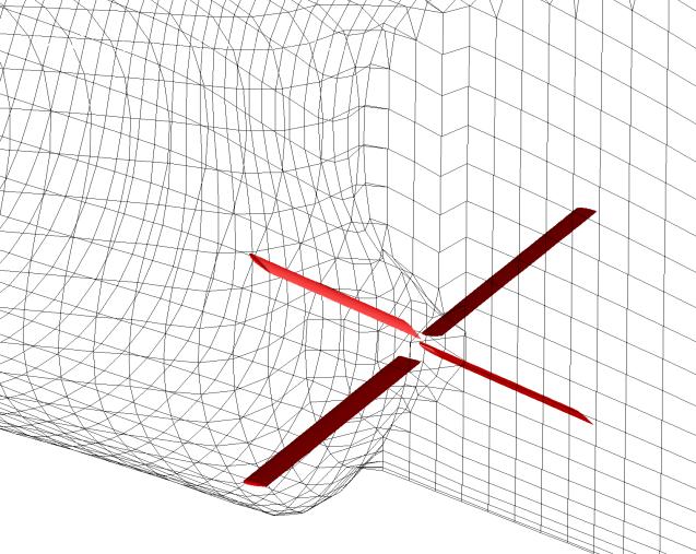
The well-known and publicly available KVLCC2 hull was used for the present investigation. This hull is characterizedbyasortofphysicallypowerfulvortex arrangement created in the astern bilge part that enters the propeller plane and creates a hook like formedgetup.
The hull was appended with a couple of stators on eachsidejustinobverseofthepropellerthatshould modify the get up by minimizing the velocity gradients and there by an enhanced working conditionforthepropeller.
The picture below shows the configuration of the stators (red blades) a surface grid on the hull. The angles of the stator wings were varied to find an optimalsolution.
International Research Journal of Engineering and Technology (IRJET) e-ISSN:2395-0056
Volume: 11 Issue: 09 | Sep 2024 www.irjet.net
6. OPTIMIZATION PARAMETERS
The optimization process typically involves tweakingseveralparameters,including.
6.1 Blade Angle:
The angle of the stator blades relative to the incomingflow.
6.2 Blade Number and Spacing:
The number of blades and their spacing can significantlyinfluencetheflowpattern.
6.3 Blade Shape and Size:
Different shapes and sizes can affect the flow dynamicsinvariousways.
7. COMPUTATIONS
The calculations were approved out at model scale withaReynoldsnumberof4.6x106.
ThebackdropnetworkwasshapedwithXGRIDfrom a counterbalance file while the stator wings were generated using a parametric copy included in XCHAP.
Inarrangetodropoffthecomputationaltimeforthe optimization a somewhat uncouth net with around 400000cellswasused.
The calculations started with an essential answer that was iterated for 3500 iterations until the flow groundwasconverging,andthereaftertheoptimizer inprogresstodiffertheanglesofthestator wings.
p-ISSN:2395-0072
Each innovative case was restarted from the necessaryoneanditeratedfor35iterations.
An Ensample study was performed by changeable thepitchofthewingsintherange-15to15degrees tofindanoptimumconfiguration.
The utmost variation in the wake circumferential allocationwasselectedasthepurpose.
8. METHODS OF OPTIMIZATION
8.1 Computational Fluid Dynamics (CFD)
Computational Fluid Dynamics (CFD) software is a class of tools used to simulate fluid flows, heat transfer, and other related phenomena using numerical methods and algorithms. These tools are widely applied in industries like aerospace, marine,
Fig1.1-PRE SWRIL-STATOR BLADE
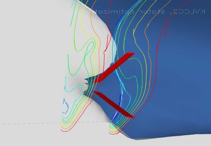
Fig1.2- PROPELLER FLOW
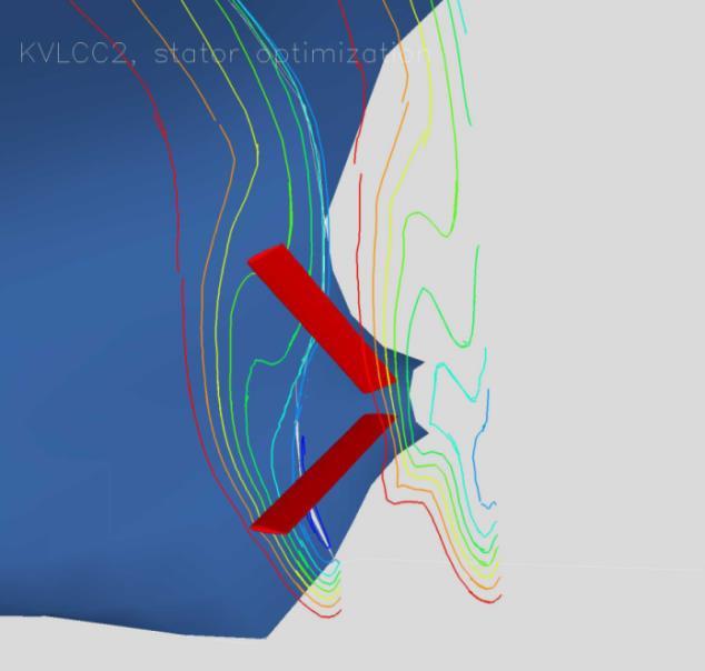
Fig1.3 PROPELLER FLOW
International Research Journal of Engineering and Technology (IRJET) e-ISSN:2395-0056
Volume: 11 Issue: 09 | Sep 2024 www.irjet.net p-ISSN:2395-0072
automotive, and civil engineering to optimize designs, predict performance, and reduce physical testing costs. In marine engineering, CFD plays a crucial role in analyzing fluid dynamics around ship hulls,propellers,andothercomponents.
Thisisthemostcommonmethod,wheresimulations areusedtopredicthowchangesinthestatordesign will affect flow characteristics and propeller performance.
8.2 Experimental Methods:
Model testing intowingtanksorcavitationstunnels canprovideempiricaldatatorefinethedesign.
8.3 Iterative Design Process:
Often, a combination of CFD and experimental methods is used in an iterative process to converge onanoptimaldesign.

9. CONCLUSION
The entire study was finished within 48 hours as wellascasesetupandpostprocessing.
It was established that the wake can be optimized withdeferencetotheselectedcriteria.
The best case had minor variations for the total wake in the circumferential trend and the velocity contours in the propeller plane were extra surrounding.
Pre-swirl stator optimization is a crucial aspect of modern marine propulsion design, aimed at achievinghigherefficiencyandreducingoperational costs.
By carefully designing and optimizing the stator, shipbuilders can create more energy-efficient vesselswithlowerenvironmentalimpacts.
The incorporated design atmosphere of VESSELFLOW Design tie together allows the designers to study and optimize the flow around appendedhulls.
The strong and bendable solver feature overlapping grids method can be controlled from simple to use and commanding graphical boundary that includes alsooptimizationapparatus.
REFERENCE
[1] Ship Resistance and Propulsion: Practical Estimation of Propulsive Power by Anthony F. Molland,StephenR.Turnock,andDominicA.Hudson.
[2] Energy Efficiency in Ships: Preparing for the New Regulations byPabloNarkunandGeirHovland.
[3] Ship Design and Performance for Masters and Mates byBryanBarrass.
[4] Marine Propellers and Propulsion by John Carlton.
[5] Marine Renewable Energy Handbook by BernardMulton.
[6] The Naval Architecture and Marine Engineering Series byD.G.M.Watson.
BIOGRAPHIES:

I am pursuing B.E final year Marine Engineering cadet at PSN College of Engineering & Technology, Tirunelveli, and Tamil Nadu.
Fig1.4-CFD SOFTWARE
International Research Journal of Engineering and Technology (IRJET) e-ISSN:2395-0056
Volume: 11 Issue: 09 | Sep 2024 www.irjet.net p-ISSN:2395-0072


I am pursuing B.E final year Marine Engineering cadet at PSN College of Engineering & Technology, Tirunelveli,andTamilNadu.
Project Guide cum Assistant Professor PSN College of Engineering & Technology, Tirunelveli, Tamil Nadu. Also having 15 years’ experience in Oil and Gas industries. SpecializationinNDTand worked variesGulfCountries.
Project Guide cum Assistant Professor PSN College of Engineering & Technology, Tirunelveli, Tamil Nadu. MEO Class-IV Marine Engineer and workedvariesCountries.
© 2024, IRJET | Impact Factor value: 8.315 | ISO 9001:2008