
International Research Journal of Engineering and Technology (IRJET) e-ISSN: 2395-0056
Volume: 11 Issue: 09 | Sep 2024 www.irjet.net p-ISSN: 2395-0072


International Research Journal of Engineering and Technology (IRJET) e-ISSN: 2395-0056
Volume: 11 Issue: 09 | Sep 2024 www.irjet.net p-ISSN: 2395-0072
Ravindra
Kachare1 Mohan Patwari2
1Team Lead, Tata Technologies, ERC, Chassis, Tata Motors, Pune Maharashtra, India
2Tech Lead, Tata Technologies, ERC, Chassis, Tata Motors, Pune Maharashtra, India
Abstract - Caster angle is one of the main parameters of suspension system which has significant impact on a vehicle’s handling at time of cornering, straight-line stability and high speed stability. Caster angle is a slope created by an imaginary line passes from upper ball joint to the lower ball joint i.e. KPI (king pin inclination) to center line of tyre when seen from side of vehicle. Caster angle is said to be positive if strut top point in MacPherson suspension is inclined towards rear side of vehicle or KPI line inclined towards vehicle rearward. Caster angle is said to be negative if KPI inclined towards vehicle front which creates angle with center line of front tyre. Positive and negative caster angle set in vehicle depending upon the suspension system geometry requirement and overall vehicle performance. Caster value varies if strut top point and lower ball joint contributor parts are not in specified tolerance limit which changes the king pin inclination. To check maximum or minimum caster variation as per the tolerance given in part like control arm, chassis, wheel end, strut etc., a tolerance stackup analysis is performed which helps to get maximum and minimum caster value. Caster angles are generally used to improve vehicle’s steering balance at time of high speed and cornering. Positive caster increases steering effort also the amount of caster set into vehicle’s suspension system is a balance between stability and steering effort.[5].
Key Words: TolerancestackupanalysisforcasterangleandKPIvariation.
Infieldofautomobileengineering,suspensionplaysanimportantroleintermsofridecomfort,corneringetc.Tomaintainall thevehicleperformance,allthesuspensionparametertobedesignedinsuchawaythatitmaintainitsqualitylikedesign, drafting, manufacturing and inspection. Suspension design is very complex structure which is the combination of both kinematicsaswellasitshouldalsobearallroadload.Thekinematicsofsuspensionincludesmanysuspensionrealtimetravel and turn via rack and pinion. Kinematics plays a major role in suspension desired application besides the kinematics suspensionsystemshouldbeartheroadloadconditionwhichincludes1G,2G,3G,loadwhichgeneratesthrougharticulation, corneringandweightshiftwhilebrakingandaccelerating.
Thiscomplexsuspensiondesignrequiresaninspectionofallcomponentstobe100%defectfree.Suspensioncomponents should be defect free from design, CAE, manufacturing. This topic focuses mainly on the component and assembly level tolerances.Definingtolerancesisthegoodpractisebeforepartmanufacturing.Here,tolerancearethemostcommonparameter thatareavailableandtobegiveninthedrawingasperthebestpractisesofdesignerbuthowthetoleranceofcomponentwill affectthetolerance ofassembly?Thepurposeofprovidingtoleranceisto ensure functionality,improvescommunication betweendesignerandmanufacturer.
Thetolerancesinthedrawingaretobedefinedinsuchawaythatthesuspensionparametersuchascasteranglenominal valuesremainsintothespecifiedtolerancezone,Ideallythecasterangleinpassengervehiclearekeptas3to5degreewhich variesasperchangeinvehicleweightatfrontaxialandrearaxial.Inthisexerciseallthetolerancearedefinedwithfollowing ASMEY14.5standard,Whiledesigningthekinematics,testingroadloadandprovidingtoleranceinthedrawing,thetolerance stackup are need to be performed. The tolerance stackup is proven method to resolve the upcoming issues to allow the applicationofanyassembly.Italsoincludestheprocessofassemblingtheassemblytomakesuspensionwork.

International Research Journal of Engineering and Technology (IRJET) e-ISSN: 2395-0056
Volume: 11 Issue: 09 | Sep 2024 www.irjet.net p-ISSN: 2395-0072
Theflowdiagram1ofresearchhasgivenbelowforindepthdetails.
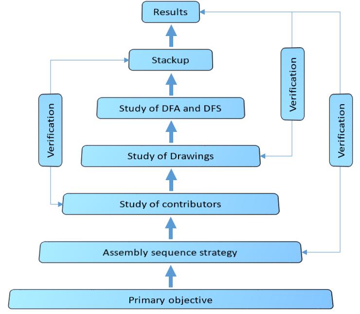
Fig. 1 Flowdiagram
Firststageistoidentifyprimaryobjectiveoftheexercisewhichincludetherequirementofcasteranglevariation,hardpointsuch asstruttoppointandlowerballjoint,Secondstageistolookouttheassemblysequencestrategy,thirdstageistostudy the contributorswhichplaysanimportantroletocheckhardpointsuchasstruttopandlowercontrolarm,lowerballjointandking pininclination.Fourthstageistodostudyofallfrontsuspensioncomponent,assemblydrawingtolerancesandGD&T,asthe fourthstageisverysensitiveandcriticaltodothisstudywhichrequirestowriteallparttolerancesatoneplaceforverification withtheresult.StudyofDFAandDFSisalsoimportantaswhenvehiclegoesforservicingatcustomerendthenthereare possibilitiestodoincorrectfitmentthisfitmentissuestobeconsideredinstudyoftolerancestackupanalysis.Finalstageisto startdoingstackupwithconsideringallvariationlikeprocess,drawingtolerances,partvariationthroughserviceandthisstage alsorequirestoverifytheresult,recheckthedrawings,wheelgeometrymachinevariation.Thetolerancestackupisdonewith followingabovesteps.Thetolerancestackuparedonetofollowloopmethodandthisloopmethoddividedintotwoloopswhich showtheRSSandworstcaseofimaginarylinewhichiscalledaskingpininclinationi.e.axispassesfromstruttoptolowerball jointofLCA(aboutwhichwheelrotatesattimeofsteering).
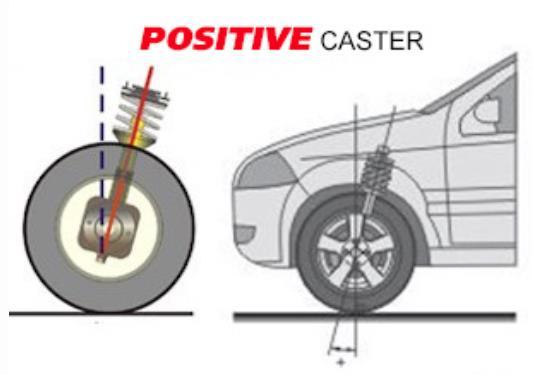
A. Casterangleispositiveiftopuprightmountingpoint(struttoppoint)ismorerearwardofthecarthanthebottom mountingpoint(lowerballjointofLCA)whenvehicleseentosideview(seeimagebelow).
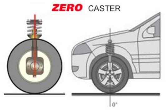
B. Casterangleisneutralorzeroiftopuprightmountingpointsandbottommountingpointareliesontheverticallineof hubandwheel(seeimagebelow).
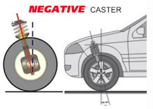
C. Casterangleisnegativeifthetopmountingpointofthelowerballjointisrearofthehubandstruttoppointisatfront ofthehubcenterline(seeimagebelow).

International Research Journal of Engineering and Technology (IRJET) e-ISSN: 2395-0056
Volume: 11 Issue: 09 | Sep 2024 www.irjet.net p-ISSN: 2395-0072
Belowistheexampleoftolerancestackupanalysismethodandthecompactfrontsuspensionassemblystructurecomponent nomenclatureaswellascontributorofkingpininclination(steeringaxis)andcasteranglevariation.

5 Frontsuspensionlayoutanditsnomenclature
AsthecontributorforcasteranglearestruttopandlowerballjointsothedirectionofloopwillbetowardstheXdirectionof vehicleco-ordinatesystem.AndthetotalvariationcanbefoundoutwithcreatingloopsofdimensionasshowninFig.6.This zoneshasbeendividedintotwopartswhichareasbelow;
Zone1(referFig.6)
Allcomponentsinzone1areanalyzedandmovedtowardsXdirectiontocalculateworstcasescenario.
BIW
BIWtoStruttopmount
Struttopmounttowheelendassembly
Zone2(referFig.6)
1’Subframefrontandrearmounting
2’SubframetoLCAmounting
3’LCArearmountingtofrontmounting
4’LCAfrontandrearmountingtolowerballjointmounting

International Research Journal of Engineering and Technology (IRJET) e-ISSN: 2395-0056
Volume: 11 Issue: 09 | Sep 2024 www.irjet.net
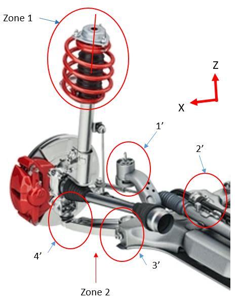
Fig. 6 Illustrationoffrontsuspensiontolerancestackupzones
p-ISSN: 2395-0072
Thepurposeofdividingtolerancestackupzonesarethattheprimary,secondaryandtertiarycontributorscanbefocusedto calculatevariationofstruttoppointandlowerballjointpoint.Andaccordingtothevariationthecasteranglecanbefoundout forfinalizingcasteranglevalue.Thezonesarecascadedintopartlevelandtheirdimensionsandtolerancesareconsideredas belowtable1andtable2.
1.BIWmountingholestolerances
0’ BIW
2. Strut top mounting pins tolerances
3.Fastenerssizeandtolerances
1’to2’ Struttopmountingtoknuckle 1. Strut top mounting to knuckle width tolerances towardsXdirection(referfig3)
1 Subframe a. Subframe mounting holes tolerances b. BIW mounting holes tolerances c.Fastenerssizeandtolerances
a. Subframe holes tolerances for lower control arm mounting
b. Lower control arm holes tolerances
2 SubframetoLowercontrolarm
3&4 Lowercontrolarmto
c. Lower control arm welding tolerances
d. Lower control arm fastener tolerances
e.Lowercontrolarmbushtolerances
a.Lowercontrolarmtolowerballjointparttolerances
b. Lower ball joint tolerances
c.Knuckleholetolerancesformountinglowerballjoint

International Research Journal of Engineering and Technology (IRJET) e-ISSN: 2395-0056
Volume: 11 Issue: 09 | Sep 2024 www.irjet.net p-ISSN: 2395-0072
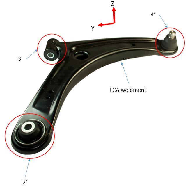
Fig. 7 Lowercontrolarmweldmentassemblyanditscontributors
Let’stakealowercontrolcomponentsfromzone2forexample,thetoleranceofLCAfrontmounting(2’),LCArearmounting(3’), LCAballjoint(4’),allbushcomplianceandallzonecomponenttohigherlevelassemblytolerancearetakenintoconsiderationto performthestackup.
3. Mathematical Expressions and Symbols
Variationincamberangleiscalculatedbytwomethods:
1. WorstcaseMethod
2. RMS(Rootmeansquare) MaximumandminimumtolerancearecalculatedwhichmayaffecttheCasterangle.
Theresultofaddingthemeansandtakingtherootsumsquareofthestandarddeviationsprovidesanestimateofthenormal distributionofthetolerancestackandtheWorstbaseandRSScanbecalculatedbybelowformula.
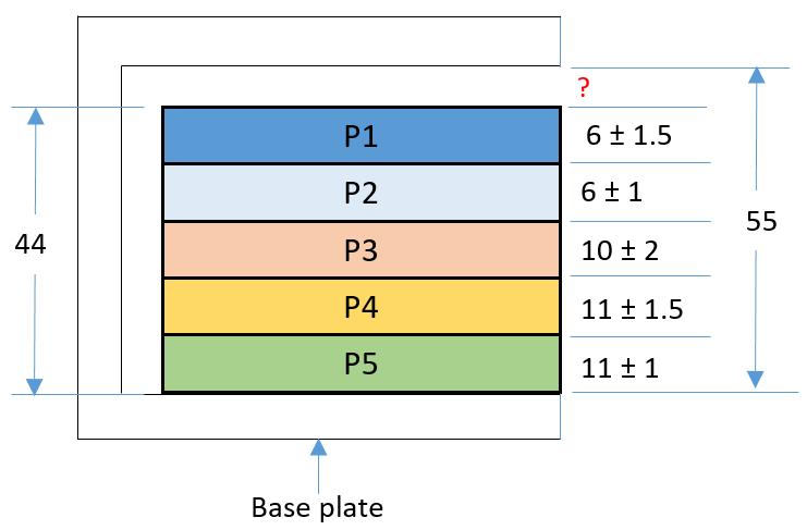
1. Worstcasescenario-Maximumandminimumgap/dimension/holessizecanbecalculatewithusingbelowexample; supposefivepartaresuchasP1,P2,P3,P4andP5arerestingonabaseplateandthethickness,toleranceofeachpart and base plate inner height i.e. 55mm are given. Maximum and minimum gap with using worst case scenario is calculated(Alldimensionsareinmm).Therearethreetypeofcasterangle,allthreetypesofcasterangleusedfor differentpurposes.Inthisstudyprimaryfocusistocheckthepositivecasteranglewhichisbeingusedinalmostalltype ofon-roadvehicle.

International Research Journal of Engineering and Technology (IRJET) e-ISSN: 2395-0056
Volume: 11 Issue: 09 | Sep 2024 www.irjet.net p-ISSN: 2395-0072
Withusingtheworstcasescenariothemaximumandminimumgapareas18and3
2. RMS(Rootmeansquare):belowisthemathematicalexpressionisusedtofindoutRMSvalueforexample

σisthestandarddeviation,sothetotaltoleranceof±3.24mminnominaldimensionofallplatewillbeappliedasperRMS.With usingsamemethodthecontributorparttolerancearetakenintoconsiderationtofindouttheKPIandcasteranglevariation.
ThemaincomponentwhichaffectCasterangledirectlyisstruttophardpointandlowerballjoint.Tooptimizethetolerances belowexerciseisalsobeendonewherethepartleveltolerancesareconsideredtofindoutfloattomountfasteners.
ThecalculatedworstcaseandRSScasevaluefromzone1andzone2aregivenasbelow.Thecrossadditionofmaximum variationfromzone1andminimumvariationfromzone2viceversagivesthetotalcamberanglevariationinwhichitcanbe convertedtodegreeanddegreetominutesasperformula(2).
NOTE: Belowdimensionstolerancesinresulttable5aretakenforcasestudyandareforexampleonly.
ThetotaltoleranceofZone2denotesthelowerballjointpointmovementinXdirectionthatchangestheKPIangleaswellasthe casterangle.ViceVerathetotaltoleranceofZone1denotesthepossibilityofstruttoppointmovementinXdirectionwhich changestheKPIaswellasthecasterangle.

Volume: 11 Issue: 09 | Sep 2024 www.irjet.net
Table5–
Worstcaseanalysisandrootmeansquareoffrontsuspensionzones
Zone2 BIW PLP to subframe
Subframe BIW mounting hole
(Clearancehole)
Zone1
StrutmountingBIW
Considerations–Themaximumtoleranceinmmmeaningisthehardpointwillgetshiftedtowardsvehiclefrontviceversa minimumtoleranceinmmwillshiftthehardpointtowardsvehiclerearward.
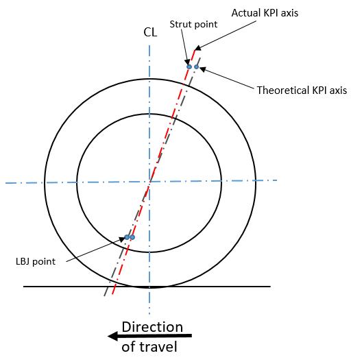
Fig. 9 Variationofstruttop,lowerballjointhardpointsinfrontsuspension
ThemovementofstruttopandbottompointwithsomeinstantchangestheKPI(markedinabovefigure)whichclearlyshows thesensitivityofhardpoints.
5.
Above example of tolerance stackup analysis is applicable for one dimensional analysis only, which is having the optimal limitationsforthisparticularcasestudy.Inthiscasestudythegeometrydimensionsfeatures,primary,secondaryandtertiary datum’s,modifierssuchasLMC&MMC,RFS(ifapplicable),basicdimensionsinparts,alllinearandbilateraltolerancesaretaken intoconsiderationtoperformthetolerancestackupanalysistofindoutmaximumandminimumcamberanglevariation.Andas pertheresultandmethodfollowedfromflowdiagramFig.1,loopmethods,itcanbeseenthatthemajorcontributor'swhich affectthecasterangleare[6];
1.BIW
2.Strut

International Research Journal of Engineering and Technology (IRJET) e-ISSN: 2395-0056
Volume: 11 Issue: 09 | Sep 2024 www.irjet.net p-ISSN: 2395-0072
3.Lowercontrolarm
4.Subframe
Thesecontributors’geometrydimensionandtolerancescanbemodifytogetthecasteranglewithintheacceptablerangewhich isdefinedaspervehicledynamics[4,5,6].
REFERENCES
[1] ASMEY14.5(2018)Dimensioningandtolerancing.AmericanSocietyofMechanicalEngineers,NewYork
[2] RamiA.MusaandSamuelHuang,Y.KevinRong“Simulation-basedtolerancestackupanalysisinmachining”
[3] ChaseKW(1999)Toleranceallocationmethodsfordesigners.ADCATSRep99–6,BrighamYoungUniversity
[4] NumericalAnalysisoftheWheelCamberoftheFrontAxleofaPassengerCarDuringCorneringDenisMolnára*,Miroslav Blatnickýa,JánDižoa,VadymIshchuka
[5] SimulatedStudyontheEffectofCamberandToeontheHandlingCharacteristicsofaCarduringCorneringT.Vijayakumar andV.Ganesh
[6] “MaximumandMinimumVariationofWheelGeometrythroughWorstCase&RSSMethod”MohanPatwari,Ravindra Kachare&SujeetKumar
BIOGRAPHIES


RavindraKachare,TeamLead,Tata Technologies, ERC, Chassis, Tata Motors,PuneMaharashtra,India
Mohan Patwari, Tech Lead, , Tata Technologies, ERC, Chassis, Tata Motors,PuneMaharashtra,India