
International Research Journal of Engineering and Technology (IRJET) e-ISSN: 2395-0056
Volume: 11 Issue: 09 | Sep 2024 www.irjet.net p-ISSN: 2395-0072


International Research Journal of Engineering and Technology (IRJET) e-ISSN: 2395-0056
Volume: 11 Issue: 09 | Sep 2024 www.irjet.net p-ISSN: 2395-0072
Jayant Bhagirath Sonawane1 , Prof. P.S. Bajaj2
1PG Student, SSGB College of Engineering, DBATU, INDIA
2 Professor, Dept of Mechanical Engineering, SSGB College of Engineering DBATU, Maharashtra, INDIA
Abstract - Vehicle chassis is considered the most important element in terms of absorbing impacts and carrying loads. This study mainly analyzes the electric vehicle chassis frame made of different materials and calculates the strength, deformation and weight of the frame under different operating conditions. To achieve this, the frame chassis was designedbyfusion360andtestedonAnsyssoftwaretoobtain the predicted results. For maximum accuracy, different components are given to the chassis frame to measure the deformation and impact on the safety and durability of the product.Theresultsareeasilyexplainedandafewscreenshots are added for better understanding of the tests.
Key Words: E rickshaw chassis frame, fusion 360, Ansys software.
The search for sustainable, safe, clean and environmentally friendly fuels never ends. Carbon-based fuelssuchasfossilfuelsarenotsustainableandareharmful to our environment. Some other energy sources are renewable energy sources, which include all types of petroleum and non-fossil fuels such as solar, wind, tides, hydroelectric and biomass. Among these elements, solar energyispreferredbecauseitprovidesthecleanestenergy for the longest period (up to thousands of years). Photovoltaicelectricityproductiondoubleseverytwoyears andhasbeenincreasingbyanaverageof48%annuallysince 2002.Photovoltaicsystemshavebecometheworld’slargest sourceofenergyduetotheirenvironmental,economic,and social benefits. The only limitation to solar energy as an undisputedsourceofenergyisourunderstandingofhowto develop effective and efficient technologies that make it possible.Nothinginthisworldisfree,butwhatifwecould finda waytorideforfree?Infact,itwouldbegreatifour carscouldmovewithoutspendingbillionsofdollarsevery year buyingfossil fuelsand dealing with natural disasters thatcauseleavestofall.Ifwecoulddriveacarthatrunson solarenergy,itwouldbethecarofourdreams.Asolarcar willusesolarenergyfromasolarpanel.Asolarpanelisa componentofasolarcell,alsoknownasaphotovoltaiccell, and is an electrical device that can convert solar energy directly into electricity through quantum mechanical transitions.Theyaresilent,donotpollutetheenvironment, do not rotate, and require very little maintenance. The electricitygeneratedwilldamagethebatteriesthatpower thecar'sengine.Asaresult,wewillhaveanelectriccarthat can run on "free" energy, does not produce harmful
emissions,producesallitspoweratallspeeds,andhasvery lowmaintenancecosts
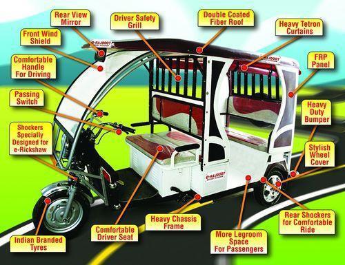
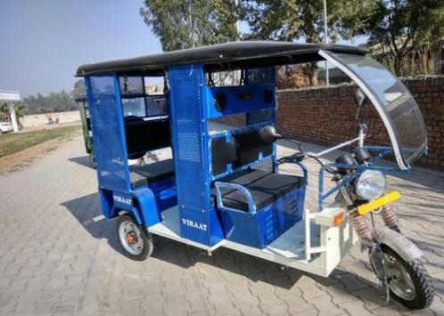
Since2008,electricrickshawshavebecomepopularin some cities as an alternative to auto rickshaws and rickshaws. The reasons for this preference are their lowercostandeaseofusecomparedtorickshaws.They are widely accepted as an alternative to petrol/diesel/CNG auto rickshaws. They are threewheelers that use electricity between 650 and 1400 watts.TheyaremanufacturedonlyinIndiaandChina. Battery-powered rickshaws can become a low-cost transportation option for the poorest of the poor, the low-income people, if transportation facilities are systematicallydemonstrated.

International Research Journal of Engineering and Technology (IRJET) e-ISSN: 2395-0056
Volume: 11 Issue: 09 | Sep 2024 www.irjet.net p-ISSN: 2395-0072
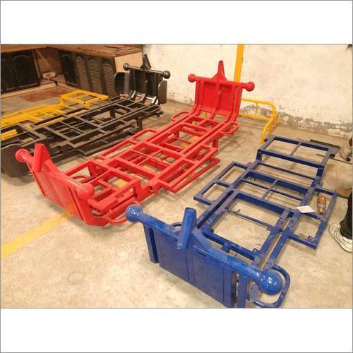
Thechassisisthemanufacturer'sloadthatsupportsthe structureandfunctionoftheproduct.Anexampleofa chassisistheframe,whichisthelowerpartofthemotor vehicletowhichthebodyismounted;
The project focuses on the combination design and development of a three-wheeled solar vehicle with aerodynamicpowerandlong-distancetravelsuitablefor Asiandrivers.Thisimportantpartisdoneasfollows:
1.Buildathree-wheeledsolarcarchassisusingaluminum andfiberglass.Analyzetheframe-framechassisproperties andexploretheeffectsofstress,torsionanddeflectionon the chassis. Perform fluid dynamics analysis to determine positiveandnegativepressureanddragforces.Thechassis provides support and rigidity to the vehicle. The chassis usually consists of a series of cross members that cross a pairoflongcablesandchannels.Thecrossmembershavea smallcrosssectiontoprovidelongstoragespace.Thesafety ofthechassisisanimportantpartofthedesignandmustbe considered at every stage. Generally speaking, the basic typesofchassisincludethebackbone,ladder,midframeand monocoque.Differenttypesofchassisstructurewillleadto differentcharacteristicsofeachchassis.
Toincreaseefficiency,roundtubescanbeused forframe members.Thismakesiteasiertocutthejointsandremove the mounting points. Building a jig is very labor intensive and can use as many components as the chassis itself. To improve chassis manufacturing, the chassis should be designedtobe"self-clamping",atypethatallowsthechassis to be built in separate pieces and then clamped together. This reduces the time and materials required to build the chassis, thus reducing costs. It is worth noting that this method is suitable for a single operation, which is the
documentfortheconstructionofthischassis.However,ifa largenumberofidenticalchassisaretobeproduced,thecost ofmakingtheapparatusisreasonableasitreducesthetime requiredtomakeeachchassis.
Asarule,themainloopshallbemadeofasinglepiece,nonuniform,continuous,closedsectionsteelpipe.Themainloop shall commence at the lowest member on one side of the frameandshallextendupward,upwardanddownwardto thelowestmemberoftheframe.Inthesideviewofthecar, thegreaterpartofthefirstlooppreventingrollingshallbe withintendegrees(10°)ofitsverticalconnectiontothefirst framestructure.Whenviewedfromtheperspectiveofthe car, each deflection of the connection between the upper partofthemainrollingringandthemainstructureofthe frame shall be supported on the ball of the main ring supporting the structure and the pipes shall meet the requirements. Rolling ring support Rules.11.6 In the car Viewedfromthefront,themainsheaveisfixedtothemain structureoftheframeandtheverticalmembersofthemain sheavehaveaminimumlongperson(internaldimension)of 380mm(15in.)..
Main Hoop braces must be constructed of closed section steeltubingperRule.TheMainHoopdevoirbesupportedby twobracesspanningintheforwardorrearwarddirectionon twaintheleftandrightsidesoftheMainHoop.Intheside perspectiveoftheFrame,theMainHoopandtheMainHoop braces devoir not lie on the aforementioned side of the vertical line by wayofthe topoftheMainHoop, i.e.if the MainHoopbowsforward,thebracesdevoirbeforwardof the Main Hoop, and if the Main Hoop bows rearward, the bracesdevoirberearwardoftheMainHoop.TheMainHoop braces devoir be attached as adjacent as possible to the crownoftheMainHoopbutnotmorethan160mm(6.3in) beneath the highest-most surface of the Main Hoop. The includedangleformedbytheMainHoopandtheMainHoop bracesmustbeatleastthirtydegrees(30°).Seethefigure. The Main Hoop braces must be straight, i.e. without any bends. If any item which is farther, the envelope of the PrimaryStructureisattachedtotheMainHoopbraces,then extrabracingdevoirbeaddedtohamperbendingloadsin thebracesinanyrolloverattitude.
Chassisisconsideredasoneofthemainstructuresofthe car.Itisusuallymadeofsteelframeandsupportsthebody and engine of the car. To put it simply, car chassis or car frameistheskeletonthatbringstogethermanycomponents such as engine, tires, brakes, steering gear and drivetrain. Chassisisusuallymadeofheavysteelorcompositeplastic and provides the strength required to support the vehicle andtheload.HereIhavelisteddifferenttypesofcarchassis

International Research Journal of Engineering and Technology (IRJET) e-ISSN: 2395-0056
Volume: 11 Issue: 09 | Sep 2024 www.irjet.net p-ISSN: 2395-0072
suchasladderchassis,skeletalchassis,monocoquechassis and tubular space frame chassis (Wake ham, 2009). The ladderframeisconsideredoneoftheoldestvehiclechassis designsandisstillusedtodaybySUVs.Itresemblesaladder, consistingoftwolongrowsconnectedbyseveralexternal andtransversesupports.Thesideandtransversemembers providerigiditytothestructure(Wakeham,2009).Usually madeoffiberglass,itconnectsthefrontandrearaxlesand carriesmostoftheoverallstrengthoftheframe.Thevoidin thestructureisusedtoaccommodatethedriveshaftinrearwheeldrivesituations.Inaddition,thedrivetrain,engineand suspension are all attached to the chassis. This type of chassisisstrong enoughto supportsmall carsandiseasy and cost-effective to manufacture (Wake ham, 2009). . A monocoquechassisisasingle-piecechassisthatshapesthe shapeofthecar.Aunibodychassisismadebyweldingmany piecestogether.Itdiffersfromtheladderandbodychassisin thattheyareintegratedwiththebody;theladdersupports onlytherigidelements.Thedemandformonocoquechassis hasincreasedduetoitscosteffectivenessandsuitabilityfor robotic production (Christopher, 2004). Since the ladder chassiswasnotstrongenough,racingengineersdevelopeda 3Ddesigncalledatubularspaceframe.Thetubularpartof thechassisusesalargenumberofcirculartubes(sometimes squaretubesareusedtoalloweasyconnectiontothebody panel,butthecross-sectionsprovidethehigheststrength), arrangedindifferentdirectionstoprotectagainsttheforces fromallsourcesofenergy.Thesetubesareweldedtogether toformacomplexstructure.Tomeettheincreasedstrength requirementsofhigh-performancesportscars,thetubular spaceframechassisusuallyhasastrongstructureunderthe twodoors.Comparedtoladderandmonocoquechassisof the same weight, the tubular space frame chassis is very stronginallrespects.Figure3.1belowshowsanexampleof theTVR Tuscantubularspaceframechassis(Christopher, 2004).Forexample,LotusEngineeringhasbeenproducing cars with aluminum chassis for many years. Lotus successfully explained that not all chassis are welded because aluminum would lose its strength when welded. Theydecidedtouseonlyscrewsandadhesivestoholdthe chassis together. When Lotus first introduced the lowvolumeEliseconceptin1996,thecompany'smanagement was primarily concerned about what kind of hybrid car would be accepted by the market, but the technology has proventobesogood(over23,000carshavebeenproduced) thatitcouldbecomethebasisfornewhigh-endbusinesses andhelp bring morealuminum-poweredvehiclesintothe mainstream(Whitfield,2004).
What is Modelling?
Modelingisessentiallythecreationofmodelsrepresented
in3Dspacewiththedesiredshape,size,etc.,Forexample, sincePro/Ecanbeusedtorepresentthedesign,thereare someconditionsandguidelinesthatmustbefollowedfora gooddesign:-
·Designisaprocessthatanalyzesthestability,strengthand rigidity of the structure. structure. · The main purpose of analysis and design is to create a structure that can withstand all the equipment that does not work when needed. If the design or design is wrong or the actual productexceedsthedesign,theproductwillnotdoitsjob, whichwillhaveseriousconsequences.
Todesignandfabricateanimmenseperformance racing vehicle which will be intact by ergonomically, economicallyandbyallmeanssafetyheedsfollowingmain parametersweresetbeforethedesigning;onwhichwhole designprocessiscarriedout,
·DriverErgonomics.
·Serviceabilityandmaintainability.
·Maneuverability
·Designofflexiblerollcage.
·Useofoptimumpowerefficiency.
·Costofthecomponents.
To meet all above considerations and for ease in designing;allsystemsweredesignedindividuallyalongwith mutualspecificationsconsiderationsforinterchangeability.
·RollCage
·SteeringSystem
·BrakingSystem
·PowertrainSystem
Design of the Eco-kart is to be taken into considerationi.e.Designofanycomponentisconsistingof threemajorprinciples:
·Optimization
·Safety
·Assuage
Themainobjectiveoftherollcageistocatera3dimensionalprotectedspaceoverthedriverthatwillfoster thedriversafe.Itssecondaryobjectivesaretofosterreliable mountinglocationsforperipherals,beappealing,lowincost, andlowinweight.Theseintentionsweremetbycullinga rollcagematerialthathassuitablestrengthandalsoweighs lessgivingusaninfluenceinweightreduction.A low-cost roll cage was bestowed through material selection and assimilatingmorecontinuousmemberswithbendsinstead ofacollectionofmembersweldedcollectivelytocutdown manufacturingElementAnalysis.Wefocusedoneachpoint ofrollcagetoenhancetheperformanceofvehiclewithout failure of roll cage. We began the task of designing by pervasiveresearchofgokartrollcagethroughfiniteelement analysis.Ourframe’sdesignisshownbelow;

Volume: 11 Issue: 09 | Sep 2024 www.irjet.net p-ISSN: 2395-0072
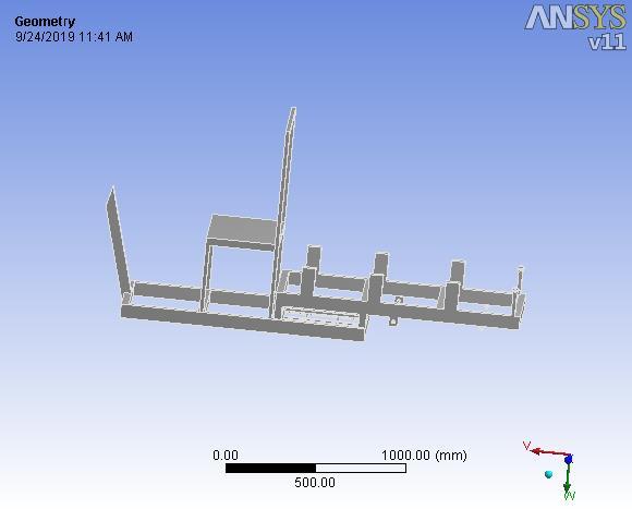
Figure4Geometry
Once cad modeling of the frame structure is contrived by using solid works, then this design is investigatedbymethodofFiniteElementAnalysis.Wehave used ANSYS (workbench) software for Finite Elemental Analysis RESULT. We first imported the solid works file modelinANSYS(workbenchby)IGESModelformat,then imparted the properties of material & defined the crosssectionoftubecreatedcomponent,thendiscreditedby3D meshing,andthenappliedloadandfinallyconstrained.The final analysis is shown in ANSYS. We have to lower the deformation and stresses and target to least weight of chassis, the flow chart of entire process is shown in the belowfigure
Finally,drawingscanbecreatedeitherfrompartsor assemblies.Viewsareautomaticallygeneratedfromthesolid model, and notes, dimensions and tolerances can then be easilyaddedtothedrawingasneeded.Thedrawingmodule includes most paper sizes and standards (ANSI, ISO, DIN, GOST,JIS,BSIandSAC)
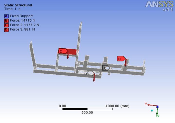
Thematerialschosenmustbeabletowithstandalltypesof environments so that the final product results are better thanfailure.Themodelhereistheframeandchassisofthe eco-kart.Theselectionofmaterialsforthechassisismade bycomparingthedifferentpropertiesoftheseelementsand followingthefollowingorderofpriority:-
· The strength of the materials must be high. There are sections.%,otherwisethepearlwillbebrittle)
·Otherimpurities
·Thematerialalsoplaysanimportantrole.Thechassisfor thebestandsafestresults.Thechassisissubjectedtoalotof force during movement and must remain stable without flexing,berobustenoughtoabsorbvibrationsandworkwell athightemperatures.Thereisnolaginthekart.Therefore, thechassismustbemodifiedtoactasasuspensionandmust bestrongenoughnottobreakorbedamagedduringitslife. In order to ensure the safety of the driver, the equipment musthavegoodstrengthanddurability.Thechassismaterial isthemainstructureinthedesignandconstructionofgokarts.Although thetubular spaceframechassisisheavier thanthemonocoquechassis,thetubularspaceframechassis was eventually accepted because it was cheap to manufacture,requiredsimpletools,andthedamagetothe chassiswaseasytorepair.Tubularsectionscancarrymore thanakilogrammorethansolidorsquaresections.
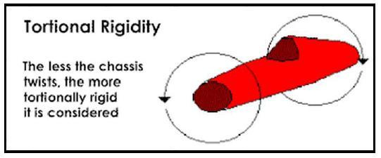
Theprincipleofchassisdesignisthatthechassismustbe designedtoprovidetorsionalrigidityandlightnessinorder to provide good control of the vehicle. By definition, torsionalrigidity(TR)referstotheabilityofthechassisto resist torsional forces or bending forces. In other words, torsional rigidity is the torque that must be torqued to a certainlevelontheframe.Theserestrictionsalsoapplyto theframechassis.Ingeneral,theeffectoftorsionalrigidity onthefieldisdifferentfromthatofthemonocoquechassis duetoitsdesign,butthemodelusedtopredicttheresultsis thesameasforthemonocoquechassis,whichisdifficultto torsion. shows the torsional stiffness used for the racing chassis.(Matt,1999)

International Research Journal of Engineering and Technology (IRJET) e-ISSN: 2395-0056
Volume: 11 Issue: 09 | Sep 2024 www.irjet.net p-ISSN: 2395-0072
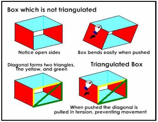
According to the above explanation, the chassis must be designedwithhightorsionalstrengthtoresisttorsionalor twistingforces.Inordertoincreasethetorsionalstiffnessof the chassis, the tube configuration should be taken into account.Thetorsionalstiffnessisincreasedfromtheinput framemembers.Theprincipleistoplacetheframemembers inatriangleasshowninthepicture.
3.6 ADVANTAGES OF SELECTED CHASSIS
Since the Spaceframe chassis is the most suitable chassis typefortheWorldSolarChallengemodeldesigncompared tootherchassistypes,I decided touse thisconceptin my project.) Since the system takes a triangular shape, it will providemaximumstrengthandminimumdesigndeflection comparedtootherchassistypesthankstothesupportofthe pipechannels.Therefore,significantsavingscanbeachieved ininitialcosts.Thismeansthattheframechassisdesignwill improvethestiffness/weightratio.
3.7 CHASSIS DESCRIPTION
There are many things that are not considered when buildingtheframeofasolarcar.Duetotheimportanceof lowaerodynamicdrag(Rocheetal.,1997),thedesignofthe frame is very difficult. The frame also needs to meet the required strength and stiffness for all loads. In addition, mounting points must be provided to connect different components such as battery components, electronic components, suspended components, body panels, etc. Therefore,theteamchosetouseatraditionalspaceframe instead of a monocoque structure. Although composite monocoques can be very light, they are very difficult to calculate and manufacture, which often makes the body stronger (Potter Kevin, 1997). The space frame is very efficient.Thebendingmomentisdistributedintheformof tensionandcompressionloadsalongthelengthofeachtube. Therefore, the strength calculation can be accurate and
simple. Manufacturing can be done by welding extruded pipestogether.
Computer-aided design (CAD) is the use of various computer-aideddesigntoolstoassistengineers,architects, and other designers in their design work. It is the initial geometrycreationtoolintheproductlifecyclemanagement process,withsoftwareandsometimesspecializedhardware. Available software packages range from 2D vector-based drawingto3Dparametricsurfaceandroughdesign.
4.1.1 Introduction:
CADisusedtodesignandmanufactureproductsthatcanbe end-userproductsorintermediateproductsusedforother products.Cadisisalsowidelyusedintoolsandmachinery usedbymanufacturingcompanies.Cadisisalsousedinthe design and construction of all types of construction, from small homes (houses) to the largest businesses and industries.CADisusedthroughouttheengineeringprocess, fromconceptualdesignandlayouttodetailedengineering andanalysisofmanufacturingdetails.
4.2 INTRODUCTION TO PRO/E:
PRO/E is the industry’s de facto 3D mechanical design suite. It is the world’s leading CAD/CAM/CAE softwarethatprovidesabroadrangeofsolutionscovering allaspectsofproductdesignandmanufacturing.Itssuccess is driven by technology that enables customers to create more robust, parametric, model-based models faster and more consistently. Because PRO/E is no different in any region,inanyprocess,inanycountry,inanycompanytype, onanyequipmentbasis.Thisflexibilitymakesittheultimate flexibleengineeringsolutionforrapidacceleration.PRO/E providesflexiblesolutionsthatmeettheneedsofsmalland medium-sized businesses, materials, manufacturing and assembly,andlargecorporationsinallindustries.Electrical and electronics, automotive, aviation, shipbuilding and factory construction. User-friendly and easy to design productsandsurfaces.
4.2.1 Advantages of PRO/E:
▪ Fasterandmoreaccurate.
Once the design is complete. 2D and 3D views are easily available.
•Abilitytomakechangesinpost-production.
-Providesaperfectrepresentationofthemodelbyshowing all other dimensions to hide geometry etc. Flexibility for change.Forexample,ifwewanttochangethedimensionsof

International Research Journal of Engineering and Technology (IRJET) e-ISSN: 2395-0056
Volume: 11 Issue: 09 | Sep 2024 www.irjet.net p-ISSN: 2395-0072
the model, then all dimensions such as design, assembly, productionwillchange.
• Provides clear 3D models that are easy to see and understand.
™PRO/Esimplifiestheassemblyofapersonormodelyou create,whilealsoreducingthetimerequiredforassembly.
4.3 PRO/E INTERFACE:
Themainmodulesare:
Sketcher
Part Design
Assembly
Drafting
Sheet metal
4.3.1 Sketcher:
Pro/Esketchertoolsinitiallydraftsaroughsketchfollowing theshapeoftheprofile.Theobjectscreatedareconverted intoapropersketchbyapplyinggeometricconstraintsand dimensionalconstraints.Theseconstraintsrefinethesketch accordingtoarule.Addingparametricdimensionsfurther controltheshapeandsizeofthefeature.
Line,rectangle,palette,constrain,dimensionmodification, andtextetc.,areusedasoneofthefeaturecreationstoolsto convertthesketcherentityintoapartfeature.
4.3.2 PART DESIGN:
ThePro/Eisa3Dparametricsolidmodelerwithbothpart and assembly modelling abilities. You can use Pro/E to model simple parts and then combine them into more complex assemblies. With Pro/E, you design a part by sketching its component shapes and defining their size, shape,andinterrelationships.Bysuccessivelycreatingthese shapes,calledfeatures,youcanconstructthepart.
Thegeneralmodellingprocess-
Planningconceptofdesigning
Creationofbasefeature
Completionofotherfeatures
Analysingthepartdesign
Modifyingthedesignasnecessary
4.3.3 ASSEMBLY DESIGN:
Pro-EAssemblyDesignallowsuserstodesignwith user-controlled integration. Pro-E hierarchically creates separatepartsandsubassembliesintoassembliesbasedon relationships defined by constraints. Parametric relationships, like the part model, allow you to quickly modifytheentireassemblybasedonchangesinoneofthe components.
4.3.3.1 Top-down Assembly:
In the top-down component assembly approach, componentsaredesignedforthemselvesduringassembly andassembledusinglimitedmaterials.Thepartsyoucreate inassemblymodearesavedaspartfiles.
4.3.3.2 Bottom-up Assembly:
ProductscreatedinPartmodeareassembledinAssembly modeusingconstraints.Assemblyfilescreatedinthisway uselessdisk space because theyonlycontaininformation abouttheassembly.However,iftheassemblyismovedfrom its original location, the assembly will not open. Below or below:
Checkassembly
Updateassembly
4.3.4 DRAFTING:
Drawings and documents are real products because they take on mechanical properties. Pro-E automatically generates drawings from 3D mechanical designers and assemblies. Integration of thedrawingintothe 3Dmaster display leads to design and drawing completion. Pro-E enhances generative drawings with 2D interaction capabilitiesandarichenvironmentfordrawingdecoration andannotations.
4.3.5 SHEETMETAL:
Thin plates with a thickness between 0.006 inches and 0.249inchesareoftencalledplates.Itisoneofthesimplest materialsusedinmetalworking.Itcanbecutandbentinto variousshapes.
4.4 FEATURES OF PRO/E:
Pro/Engineer is a one stop store for any manufacturing industry. It offers effective features, incorporatedforawidevarietyorpurpose.
Someoftheimportantfeaturesareasfollows:
Simpleandpowerfultools
ParametricDesign
Feature-BasedApproach

International Research Journal of Engineering and Technology (IRJET) e-ISSN: 2395-0056
Volume: 11 Issue: 09 | Sep 2024 www.irjet.net p-ISSN: 2395-0072
4.4.1 Simple and Powerful Tools:
Pro/Engineertoolsareuserfriendly.Althoughthe executionofanyoperationusingthetoolsissimple,thetools cancreateahighlycomplexmodel.
4.4.2 Parametric Design:
Pro/Engineerdesignsareparametric.ThetermParametric means that design operations that are captured, can be storedastheytakeplace.Theycanbeusedeffectivelyinthe futureformodifyingandeditingthedesign.Thesetypesof modelinghelpinfasterandeasiermodificationsofdesign.If the model is parametric and related properly, a change in onevalue,automaticallyeditstherelatedvalues.
4.4.3 Feature-Based Approach:
Featuresarethebasicbuildingblocksrequiredto createanobject.Pro/Engineerwildfiremodelsarebasedon aseriesoffeatures.Eachfeaturebuildsupontheprevious feature,tocreatethemodel(onlyonesinglefeaturecanbe modified at a time). Each feature may appear simple, individually, but collectively forms a complex part and assemblies.
4.4.4 Parent Child Relationship:
Parent-childrelationshipsareagreatwaytocapturedesign patternsinyourdesign.Thisrelationshipiscreatedbetween featuresduringthedesignprocess.Whenwecreateanew feature, the corresponding existing feature becomes the parentfeatureofthenewfeature.
4.4.5Associative and Model Centric:
Pro/Engineerwildfiredrawingsaremodelcentric. ThismeansthatPro/Engineermodelsthatarerepresented inassemblyordrawingsareassociative.Ifchangesaremade inonemodule,thesewillautomaticallygetupdatedinthe referencedmodule.
4.5 GENERAL OPERATIONS:
4.5.1Start with a Sketch:
Use the sketch to draw a free, long "pattern" of the curve. You can then scan the sketch using extruded or rotated bodies to create objects or forms. You can then adjust the dimensions and create relationships between geometric objectstoaccuratelyrepresenttheobjectsyouareinterested in.Editingthedimensionsofthesketchnotonlychangesthe sketch,italsochangestheobjectsthatthesketchcreates.
4.5.2
Featuremodelingletsyoucreatefeaturessuchas holes, extrudes and revolves on a model. You can then directly edit the dimensions of the feature and locate the featurebydimensions.Forexample,aHoleisdefinedbyits diameter and length. You can directly edit all of these parametersbyenteringnewvalues.
4.5.3 Associatively:
. An association is a term used to describe the geometricrelationshipbetweendifferentpartsofamodel. Theserelationshipsarecreatedwhendesignersputalotof energy into creating designs. In collaborative modeling, constraintsandrelationshipsarecapturedasadesign.For example,inarelationalmodel,abeadcomingoutofaholeis associatedwiththefacethattheholegoesinto.Ifyouthen changethepattern,moveoneorbothfaces,theholewillbe updated with its relationship to the face. For more information,seeIntroductiontoPatterns
4.5.4 Positioning a Feature:
In modeling, you use placement methods (where dimensionsarepositioned)topositionfeaturesrelativeto the geometry of the model. The feature is then associated withthegeometry,andtheserelationshipsaremaintained when you change the model. You can adjust the feature positionbychangingthevalueoftheconnectiondimension.
4.5.5 Reference Features:
You can create reference features, such as datum planes,datumaxes,anddatumcoordinatesystems,thatyou canuseasreferencegeometryorastoolsforotherfeatures whenneeded.Anythingcreatedusingafeatureapplicationis associatedwiththatfeatureapplication,andthisassociation ismaintainedwheneditingthemodel.Youcanusedatum planesasreferenceplaneswhencreatingdrawings,creating features, and working. You can use datum axes to create datumplanes,placeobjectsconcentrically,orcreateradial arrays.
4.5.6 Expressions:
.Expressiontoolsallowyoutocombineyourneeds and create constraints by interpreting the relationship betweendifferentpartsofyourdesign.Forexample,youcan define the height of an extrusion to be three times its diameter, so that when the diameter changes, the height changesaswell.
4.5.7 Undo:
Use the Undo feature to revert your design to a previous statemultipletime.Itdoesn’trequirethedesignertospenda lot of time making sure everything is correct because mistakescanbeeasilyfixed.Thefreedomtoeasilymodify

International Research Journal of Engineering and Technology (IRJET) e-ISSN: 2395-0056
Volume: 11 Issue: 09 | Sep 2024 www.irjet.net p-ISSN: 2395-0072
your model eliminates the worry of getting it wrong and allowsyoutoexploredifferentwaystogetitright.
Itismuchfasterandmoreaccurate.
Onceadesigniscompleted.2Dand3D viewsarereadilyobtainable.
The ability to changes in late design processispossible.
It provides a very accurate representationofmodelspecifyingall otherdimensionshiddengeometryetc.
It is user friendly both solid and surfacemodellingcanbedone.
It provides a greater flexibility for change. For example, if we like to change the dimensions of our model, all the related dimensions in design assembly, manufacturing etc. will automaticallychange.
Itprovidesclear3Dmodels,whichare easytovisualizeandunderstand.
PRO/Eprovideseasyassemblyofthe individual parts or models created it also decreases the time required for theassemblytoalargeextent.

ANSYS is a general-purpose finite element analysis (FEA) software package. Finite element analysis is a numerical methodthatdecomposescomplexsystemsintoverysmall parts (of user-defined size) called elements. The software uses the equations that govern the behaviour of these elementsandsolvesthemall;theseresultscanbepresented inwordsorpictures.Thistypeofanalysisisoftenusedinthe designandoptimizationofsystemsthataretoodifficultto analyse manually. Systems that fall into this category are verycomplexduetotheirgeometry,scaleorbalance.ANSYS canalsobeusedinCivilandElectricalEngineering,Physics andChemistryDepartments.
ANSYSprovidesagreatwaytoexploretheperformanceof yourproductorprocessinavirtualenvironment.Thistype ofmanufacturingiscalledvirtualprototyping.
Likesolvinganyproblemanalytically,youneedto define(1)yoursolutiondomain,(2)thephysicalmodel,(3) boundary conditions and (4) the physical properties. You thensolvetheproblemandpresenttheresults.Innumerical methods, the main difference is an extra step called mesh generation.Thisisthestepthatdividesthecomplexmodel intosmallelementsthatbecomesolvableinanotherwisetoo complex situation. Below describe the processes in terminologyslightlymoreattunetothesoftware.
BuildGeometry
DefineMaterialProperties
GenerateMesh
ApplyLoads
ObtainSolution
PresenttheResults
Structuralanalysisisprobablythemostcommonapplication ofthefiniteelementmethod.Thetermstructure(oredifice) is used not only for civil engineering, such as bridges and buildings, but also for marine, aerospace, and mechanical structures, such as ship hulls, aircraft fuselages, machine bodies,andanythingelselikepistonsandmachines.
5.3.1Static Analysis
Used to determine displacements, stresses, etc. understatic loading conditions.Both linearand nonlinear staticanalyses.Nonlinearitiescanincludeplasticity,stress stiffening, large deflection, large strain, hyper elasticity, contactsurfaces,andcreep.

International Research Journal of Engineering and Technology (IRJET) e-ISSN: 2395-0056
Volume: 11 Issue: 09 | Sep 2024 www.irjet.net p-ISSN: 2395-0072
5.3.2Modal Analysis
Usedtocalculatethenaturalfrequenciesandmode shapesofastructure.Differentmodeextractionmethodsare available.
5.3.3Harmonic Analysis
Used to determine the response of a structure to harmonicallytime-varyingloads.
5.3.4 Transient Dynamic Analysis
Used to determine the response of a structure to arbitrarilytime-varyingloads.Allnonlinearitiesmentioned underStaticAnalysisaboveareallowed.
5.3.5 Spectrum Analysis
Anextensionofanalysisthatcalculatesstressandstraindue toresponsespectraorPSDinputs(randomvibrations).
5.3.6 Buckling Analysis
Used to calculate buckling loads and determine buckling mode shapes. Both linear (eigenvalue) and nonlinear bucklinganalysisarepossible.
5.3.7 Explicit Dynamic Analysis
This type of structural analysis is available only in the ANSYS LS-DYNA program. ANSYS LS-DYNA provides a comprehensivesolutiontothedetailedanalysisofLS-DYNA. Dynamic analysis is used to calculate large deformation dynamics and provide rapid solutions to complex contact problems.
In addition to the above analysis types, several specialpurposefeaturesareavailable:
Fracturemechanics
Composites
Fatigue
P-Method
BeamAnalyses
5.4 PROCEDURE FOR ANSYS
Static analysis is used to determine the stress, strain, and strengthchangesinastructureormaterialduetosignificant impact and non-impact loads, such as a constant load in response.Typesofloadsthatcanbeusedinstaticanalysis includeexternalforcesandstresses,constantinertialforces suchasgravityorrotationalspeed(non-zero)displacement, andtemperature(forthermalstrains).Staticanalysiscanbe linearornon-linear.Inourcurrentwork,weconsiderlinear staticanalysis.
.Theprocedureforstaticanalysisconsistsofthese mainsteps
Buildingthemodel
Obtainingthesolution
Reviewingtheresults.
BuildtheModel
In this step we show the job name and analysis name,weusePREP7todefinethemaintype,main constant, material and geometry model type, allowinglinearandnonlinearmodels.ANSYSlibrary contains more than 80 different object types. A unique and predefined number for each product type.Forexample.Beam94,Plane71,Solid96and Pipe16.
5.5
Young’sModulus(EX)mustbedefinedforastatic analysis.Ifweplantoapplyinertialoads(suchas gravity) wedefinemasspropertiessuchasdensity(DENS).Similarly, ifweplantoapplythermalloads(temperatures)wedefine coefficientofthermalexpansion(ALPX).
Therearefourdifferentgeometricparametersinthe preprocessor: points, lines, areas, and volumes. These settings can be used to obtain the geometric shape of the structure.Eachareaisindependentandhasuniquesymbols.
5.7
Twodifferentmethodsareusedtogenerateamodel:
Directgeneration.
Solidmodelling
Withgoodmodeling,wecandefinethegeometric spaceofthemodel,createthecontrolpointsizeand thedesiredshape,andthentelltheANSYSprogram togetallthenodesandelements.Incontrast,using thedirectenergygenerationmethod,wedetermine thelocationofeachelementintermsofsize,shape, and the connection between each element before defining these locations in the ANSYS model. Although some files can be created (using commands such as FILL, NGEN, EGEN, etc.), the direct generation method is the main part of the codeguideandrequiresus tokeeptrack ofevery part of the number mesh when creating finite elements.Thisdetailedinformationcanbedifficult forlargesamplesandcanleaveroomformodeling errors.Productmodelsaregenerallymorepowerful andversatilethandirectmodelsandareoftenthe preferredmethodfordesign.

International Research Journal of Engineering and Technology (IRJET) e-ISSN: 2395-0056
Volume: 11 Issue: 09 | Sep 2024 www.irjet.net p-ISSN: 2395-0072
The basic idea in finite element analysis is to analyse a structurethatiscomposedofacollectionofindividualparts calledelements,whichareconnectedbyasmallnumberof elementscallednodes.Loadboundaryconditionsarethen appliedtotheelementsandnodes.Thisnetworkofelements iscalledagrid.
Incontentanalysis,thelargestamountoftimeisspenton creatingcontentandnodeinformation.Thepre-processor allowsuserstocreatenodesandelementssimultaneously, thuscontrollingthesizeandcontent.Variouselementscan becreatedorgeneratedfromdifferentgeometricareas.
Thepre-processorcancontrolcellpropertiesthatneedtobe checked before finite element analysis, such as units, connections,differentconnections,etc.generatedbyvarious automaticcellgenerationfunctions.Workonnodesinstead ofdefiningthemonebyone.Thiscanbeeasilydefinedby definingfunctionsormodifyingexistingnodesifnecessary. Additionally,nodescanbedownloaded,deletedorsearched.
5.10
Aftercompletionofthefiniteelementmodelithas toconstrainandloadhastobeappliedtothemodel.User can define constraints and loads in various ways. All constraintsandloadsareassignedsetID.Thishelpstheuser tokeeptrackofloadcases
5.11
During the development and validation phase of a model, youmayneedtolookatitfromdifferentangles.Youneedto rotate the model relative to the world and look at it from differentangles.Thepre-processorprovidesthesefunctions. Throughthefeaturepre-processorwindow,userscanzoom inonpartsofthemodeltogainclarityanddetail.Thepreprocessoralsoprovidesfeaturessuchassmoothing,scaling, regions, active sets, and more. Look for good models and correctthem.
All elements are defined by nodes that define only their function.Thereisnothicknessindicatorforplateandshell elements. This thickness can be used as an entity. The attribute table must be entered for a given set of onedimensionalattributes.
Differentobjectshavedifferentproperties,forexample
Beam:cross-sectionalarea,momentofinertia,etc.Theuser mustalsodefinethematerialoftheelement.Forstaticbeam analysis,elasticmodelandPoisson'sratioareneeded.For heat transfer, thermal expansion coefficient, density and
other requirements. They can be sent to the object by adjustingthelengthoftheobject.
Thesolutionsolvestheproblemaccordingtotheproblem definition. All the tedious work of formulation and combinationofmatrixisdonebythecomputerandfinally thedisplacementorstressvalueisgivenasoutput.Someof the features of ANSYS include linear static analysis, nonlinearstaticanalysis,transientdynamicanalysisetc.
Itisapowerful,user-friendlypost-processingprogramthat usesinteractivecolorgraphics.Ithastheabilitytoexpand thescopeofresultsobtainedfromtheanalysisoffacts.The displayoftestresults(i.e.visualrepresentationofresults) can usually be presented in seconds, which takes time to measure from digital results (comparison, i.e. in tabular form).Professionalscanalsoseeimportantresultsthatare easilyoverlookedinmassesofnumericaldata.Usingthebest toolstoenhancetheimage,youcandisplay:stressprofile, displacement,temperature,etc.
Deformgeometricplots
Animateddeformedshapes
Time-historyplots
Solidsectioning
Hiddenlineplot
Lightsourceshadedplot
Boundarylineplotetc.
Theentirerangeofpostprocessingoptionsofdifferenttypes of analysis can be accessed through the command/menu mode there by giving the user added flexibility and convenience.
Seven types of analysis models in ANSYS. The following analysis models can be followed. Each type of analysis is discussedbelow:
Staticanalysis
Modalanalysis
Harmonicanalysis
Transientdynamicanalysis
Spectrumanalysis
Bucklinganalysis
Explicitdynamicanalysis
Static analysis calculates the effect of static loading on a structure,ignoringtheinertiaanddampingeffectscausedby time-varyingloading.However,astaticanalysismayinclude time variables that can be approximated as static

International Research Journal of Engineering and Technology (IRJET) e-ISSN: 2395-0056
Volume: 11 Issue: 09 | Sep 2024 www.irjet.net p-ISSN: 2395-0072
equilibrium(suchasequalwindandseismicloads)aswell asconstantloads(suchasgravityandrotationalspeed)
5.15.2
Brakesaredifficulttomodelaccuratelyandresearchis ongoingtounderstandthethermalchangesofdiscbrakes during braking. Modelling complex geometries always requires some assumptions. When making these assumptions, keep in mind the problems with theoretical calculations and the importance of not taking them, not ignoringthem.Inmodelling,weoftenignorethingsthatare not important and have little impact on the analysis. The requirements always relate to the level of detail and accuracy required for the model. The assumptions made whilemodellingtheprocessareasfollows:
1. The disc material is considered as homogeneous and isotropic.
2. Thedomainisconsideredasaxis-symmetric.
3. Inertiaandbodyforceeffectsarenegligibleduringthe analysis.
4. Thediscisstressfreebeforetheapplicationofbrake.
5. Brakesareappliedontheentirefourwheels.
6. The analysis is based on pure thermal loading and vibrationandthusonlystresslevelduetotheabovesaid isdone.Theanalysisdoesnotdeterminethelifeofthe discbrake.
7. Onlyambientair-cooling istakenintoaccountand no forcedConvectionistaken.
8. The kinetic energy of the vehicle is lost through the brake discs i.e. no heat loss between the tire and the roadsurfaceanddecelerationisuniform.
9. The disc brake model used is of solid type and not ventilatedone.
10. The thermal conductivity of the material used for the analysisisuniformthroughout.
11. The specific heat of the material used is constant throughoutanddoesnotchangewithtemperature.
Whenthebrakesareappliedtothediscbrakerotor of the car, friction generates heat, and this heat must be transmittedanddistributedacrossthecross-sectionofthe discrotor.Brakingconditionsareverysevereandrequire thermalanalysis.Thermalloadsandstructuresareaxially symmetric. Therefore, it is possible to perform an axially symmetric analysis, but in this study, we performed a 3D
analysisthatisatruerepresentationofthistemperature.In ordertoverifythestabilityofthestructure,heattestswere performedontheaboveproductandstructuralanalysiswas performed.
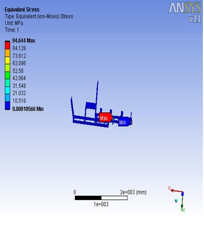
6.1 ALUMINIUM RESULTS
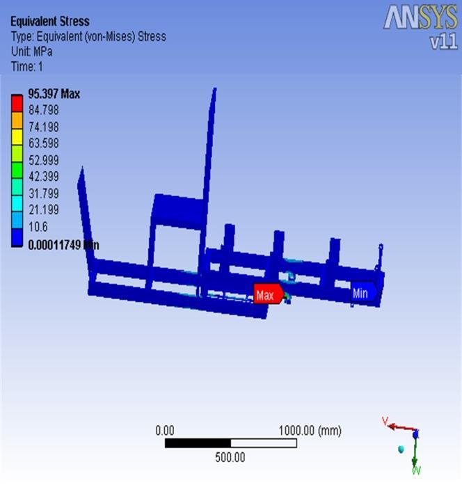
EQUALENT STRESS
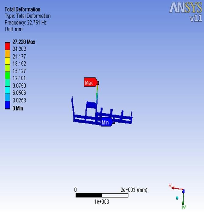

International Research Journal of Engineering and Technology (IRJET) e-ISSN: 2395-0056
Volume: 11 Issue: 09 | Sep 2024 www.irjet.net p-ISSN: 2395-0072
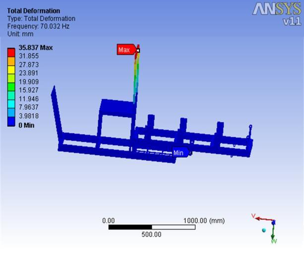
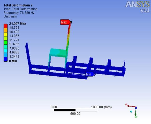
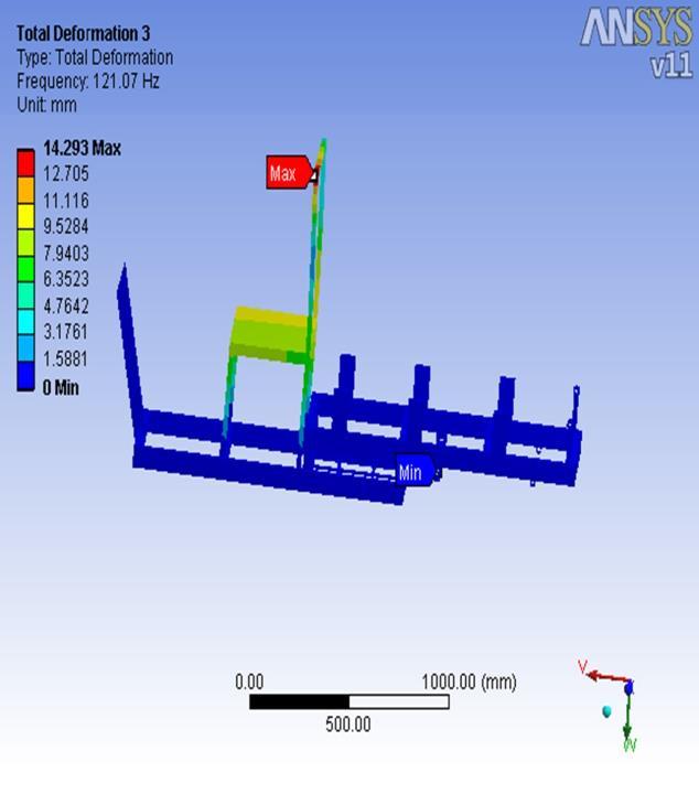
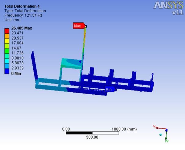
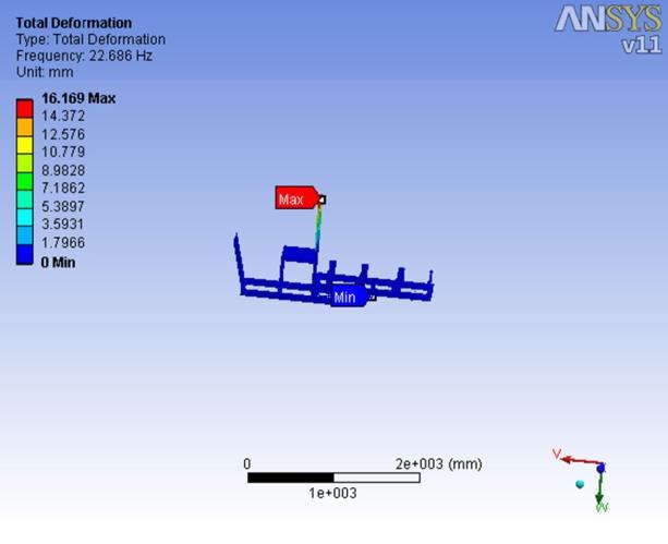
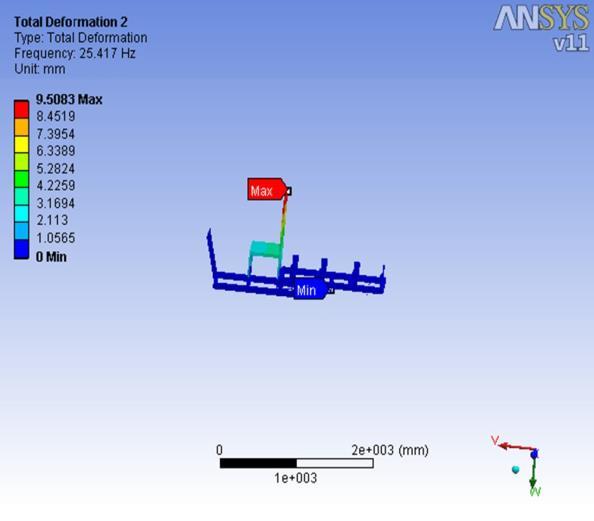
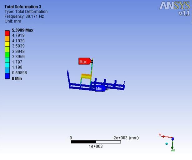
AT MODE 2 AT MODE 3
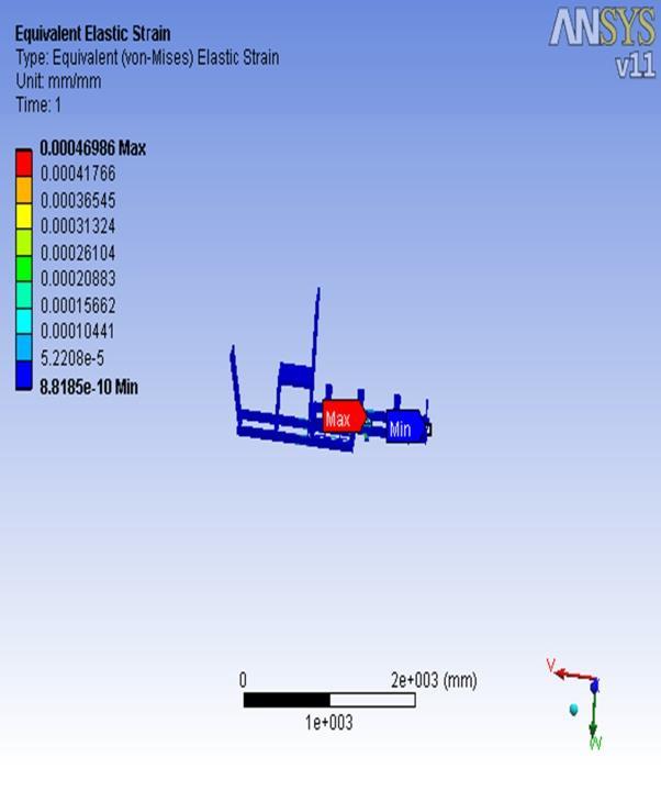
STRAIN
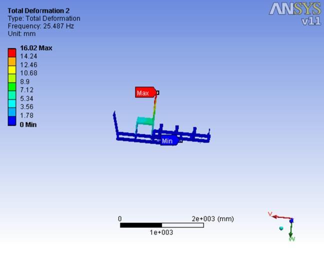
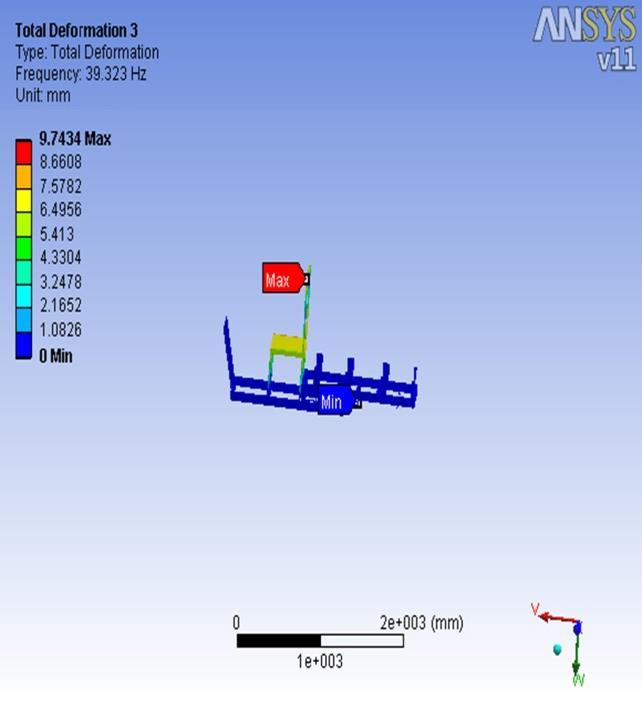
AT MODE 4
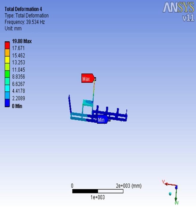
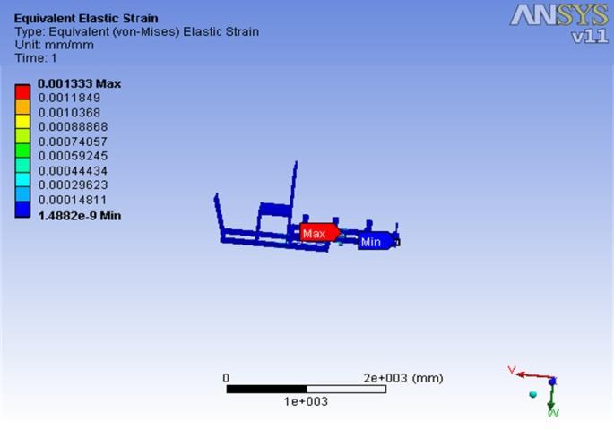
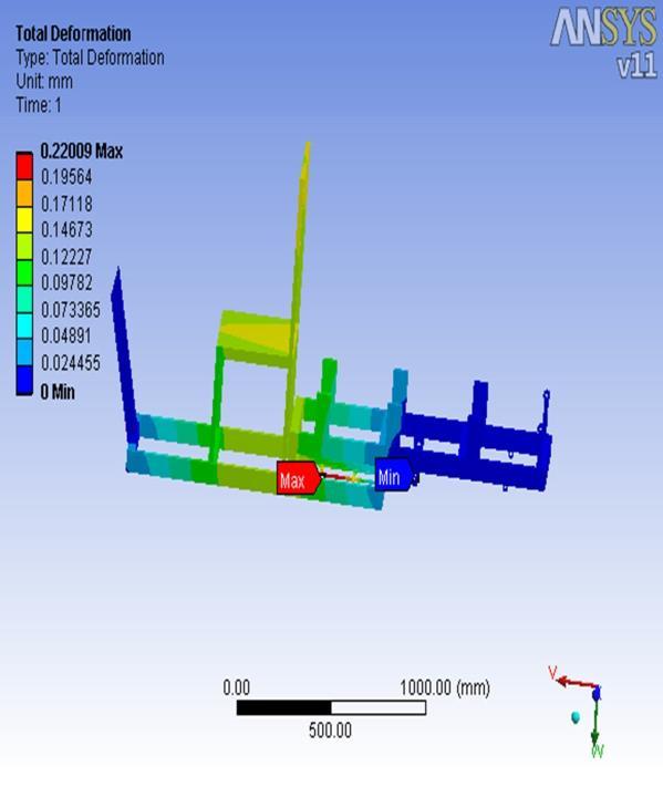
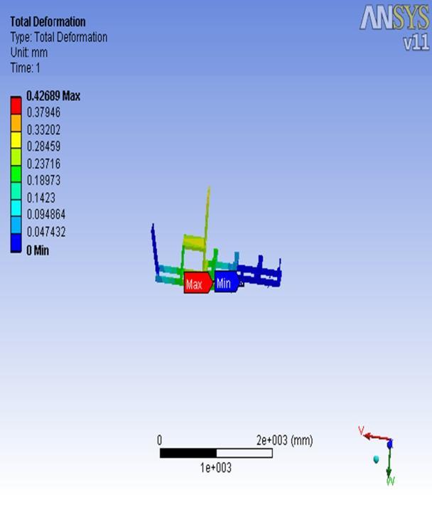
TOTAL DEFORMATION

CARBON GLASS RESULTS
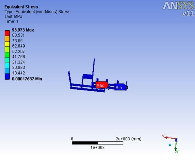
EQUALENT STRESS

International Research Journal of Engineering and Technology (IRJET) e-ISSN: 2395-0056
Volume: 11 Issue: 09 | Sep 2024 www.irjet.net p-ISSN: 2395-0072


International Research Journal of Engineering and Technology (IRJET) e-ISSN: 2395-0056
Volume: 11 Issue: 09 | Sep 2024 www.irjet.net p-ISSN: 2395-0072
EQUALENT STRESS


International Research Journal of Engineering and Technology (IRJET) e-ISSN: 2395-0056
Volume: 11 Issue: 09 | Sep 2024 www.irjet.net p-ISSN: 2395-0072
6. CONCLUSIONS
Theresultsofthestudyareasfollows
1.Muchstresscanbereducedbyribbingtheneckring.
2.Thequalityofweldsandweldedjointsshouldbedesigned toreducejointfailure.3.Stressdistributionshouldbeequal.
4.Accordingtoanalysis,someofthemneedtoberebuiltfor safetyreasons.
5.Overloadfactorsshouldbetakenintoaccounttoprovide additionalstrengthtothechassis.
Future Work for the Project
Improve efficiency by using lighter chassis material(Alloy).
Usage of more efficient Solar Panels (Carbon Nano-tubes).
Usage of Lithium Batteries for better power consumptionandreductionofweight.
REFERENCES
1. Gelmanova,Z.S.,Zhabalova,G.G.,Sivyakova,G. A.,Lelikova,O.N.,Onishchenko,O.N.,Smailova, A.A.,&Kamarova,S.N.(2018).“Electric cars. Advantages and disadvantages”. Journal of Physics: Conference Series, 1015, 52029, doi :10.1088.
2. Tektjinglie,krishnamacharprasad,ningding (2017). “The electric vehicle: a review”. International journal of electric and hybrid vehicles,doi10.1504.
3. Evangelos Ch. Tsirogiannis ,*, Georgios E. Stavroulakis and Sofoklis S. Makridis (2019). “electric car chassis for shell eco marathon competition: design, modelling and finite element analysis”. World electric vehicle journal,doi:10.3390.
4. Abdulkadir yasar, durmus ali bircan (2016), “design, analysis and optimization of chassis for anelectricvehicle”. MScthesis.
5. C. Chandrashekar a, Prashansa Agrawal b, PrithaChatterjeea,DigvijayS.Pawarat(2020). “developmentofe-rickshawdrivingcycle(ERDC) based on micro-trip segments using random selection and K-means clustering techniques”. IATSSResearch,doi:10.1016.
6. Rovan diary ali (2020). “Design and development of a chassis concept for an autonomus airport shuttle”. Degree project in vehicleengineering.
7. SadigeAkhilprasad,saikiranmaddela(2020). “design and analysis of chassis of electric solar vehicle”. International journal of engineering research&technology,vol9ISSN:2278-0181.
8. Dhvanipandya,dr.a.m.bisen(2016).“analysis of chassis in 3-wheeler E-rickshaw for weight reduction”. Internationaljournalofengineering research&technology,vol4,ISSN:2278-0181.
9. Suraj kumar, ravi girgowswami, abhishek Shukla, Pranit shinde, n.t. rathod (2021). “design and analysis of chassis for electric vehicle”. International research journal of engineeringandtechnology,vol8,ISSN:23950056.
10. Mohammad aiyan, Sumanth sagar, Sanjay Raghavs(2021).“designandoptimizationofan electric car chassis and body using structural analysisandCFD” doi:10.21203.
11. D arun, d.v. paleshwar, k. Sainath (2019). “electric vehicle chassis design and structural analysis by using CAD and CAE techniques”. International journal of research in engineering, science and management, vol 2, ISSN:2581-5792.