selected works 2009 --- 2023

jiangshen Huang architecture
portfolio Email: Jasonhuang0121@gmail.com
Jiangshen Huang
Baltimore, MD 21202
Professional Experience:
KPN Architects, LLC

selected works 2009 --- 2023
Jiangshen Huang
Baltimore, MD 21202
Professional Experience:
KPN Architects, LLC
(916)346-9861 • Jasonhuang0121@gmail.com
Baltimore, MD
Studio Architect October 2017 to Present
• Coordinated with project managers with construction site measurements, developed architectural drawings and construction documentation to assist the project approval process
• Contributed design, production, coordination, and architectural detailing as part of a multi-disciplinary team
• Consulted in the coordination of engineering systems with engineers and consultants
• Maintained close communication with the project owner and consultants on project status, design intent, and concerns
• Prepared design sketches for moderate to complex site plans
• Collaborated with the project team in all the phases of a project– from project pursuit, pre-design, schematic design to construction documents
• Prepared required design documents including: floor plans, building sections, elevations, details, wall sections, schedules and more for each architectural phase of a project
Skidmore, Owings & Merrill LLP (SOM)
I have dedicated my career to crafting designs that prioritize meticulous attention to detail and the use of high-quality materials in order to achieve a harmonious balance of design elements. With over five years of experience in the industry, I possess a deep understanding of the fundamental principles of design and construction.
My passion for architecture was ignited when I read an article by Kengo Kuma, whose philosophy of creating architecture that is both visually appealing and functional resonated deeply with me. In order to fully comprehend his words, I immersed myself in the art of sushi-making, spending two years learning from a Japanese sushi chef with 40 years of experience. Through this experience, I developed an eye for detail and an artistic sensibility that I now bring to my design work.
Chicago, IL
Architectural Designer March 2017 to April 2017
• Worked closely with a senior staff on design tasks and project approval process
• Owned and kept design artifacts up-to-date to company stand
• Used Revit to create sketches, drawings, and construction documents that align with company and CAD/BIM standards
DMAC Architecture PC
Evanston, IL
Architect Intern November 2016 to February 2017
• Created visual presentations for key stakeholders and the project team
• Designed projects under direct supervision and contributed proactively to the project team
• Assisted in construction administration including responds to RFIs, preparing sketches and addendum’s (CCDs), visited the construction site to gather information and/or prepared a punch list
• Assisted in the production of bid documents for ongoing projects
• Worked closely with architects and supported senior staff
• Executed of all phases of the architectural process: measured drawings, schematic design, 3-D modeling, and construction documents
Zhong Heng Decoration Fujian, China
Interior Designer September 2008 to September 2009
• Formulated environmental plans to be informative and visually engaging to raise productivity and sell merchandise
• Worked closely with stakeholders to determine project details such as budget, architectural preferences, purpose, and function
• Determined material requirements and costs, and presented design to stakeholders for approval
• Advised stakeholders on interior design factors, such as space planning, layout, utilization of furnishings, equipment, and color coordination
• Planned and designed interior environments for boats, planes, buses, trains, and other enclosed spaces
Education: School of the Art Institute of Chicago (SAIC)
Chicago, IL Masters of Architecture 2016
Tokyo University of the Arts Tokyo, Japan Exchange Program (Micromodern Memories) 2016
Harvard University - Graduate School of Design Cambridge, MA Career Discovery Program (Architecture) 2014 Harold
Languages:
• Proficient in Mandarin, English, Taiwanese, Cantonese, and Hakka
Skills:
• Technical skills: Revit, Sketch Up, Rhinoceros, Ecotect Analysis, Bluebeam, Adobe Creative Suite, Auto CAD, Enscape, Lumion, Arduino, Grasshopper, Computer Numerical Control (CNC) Technology, Microsoft Office, Prezi
• Artistic skills: Sketching, Sculpture, Oil Painting, Lacquer Painting, Water Color Painting, and Decorative Painting
I pursued a Master of Architecture program at the School of the Art Institute of Chicago, where I gained comprehensive architectural knowledge and skills, as well as honed my artistic sensibilities. Following my studies, I completed internships at several leading architecture firms in Chicago before joining KPN Architects, LLC in Baltimore, where I have worked on a variety of projects across different sectors.
Throughout my career, I have developed proficiency in various software programs and am able to effectively communicate my design ideas through both hand sketching and 3D modeling. Additionally, I possess a strong understanding of sustainability and strive to incorporate sustainable design principles into my work whenever possible.
In my free time, I enjoy oil painting, sketching, playing the violin, and making sushi. These experiences inform my design philosophy and inspire me to create functional and aesthetically pleasing spaces.
I am committed to pursuing my architecture license in the United States and am eager to bring my skills and expertise to a new role where I can continue to grow as a professional and contribute to a team’s success.


Size : 199,670sf

Design Start : 2020
Constructions Start : 2022( est.)
Setting : Higher Education
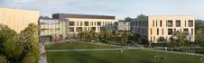
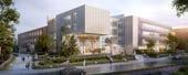
The new CAH Building will be an integral part of the Bowie State experience, collecting and connecting students across various fields of study into a facility designed to inspire collaboration and student success. The new building will be the stage upon which students are empowered to speak and destined to soar, the primary vision for the project.

The building’s massing informs the approach to the facade design and materiality, responding to specific program needs, view opportunities, environmental orientation, and shaping a series of significant new campus spaces. The highly visual nature of the programs contained within the building are manifested in the design concept of “procession”. This concept guides the building siting, shape, placement, and materials.
Responsibility
Work closely with the team to identify FF&E needs and assist in developing detailed specifications for each FF&E item, including dimensions, materials, finishes, and other features. Assist the team in Revit modeling and produce construction drawings, including exterior wall sections, roof plans, and interior elevations.
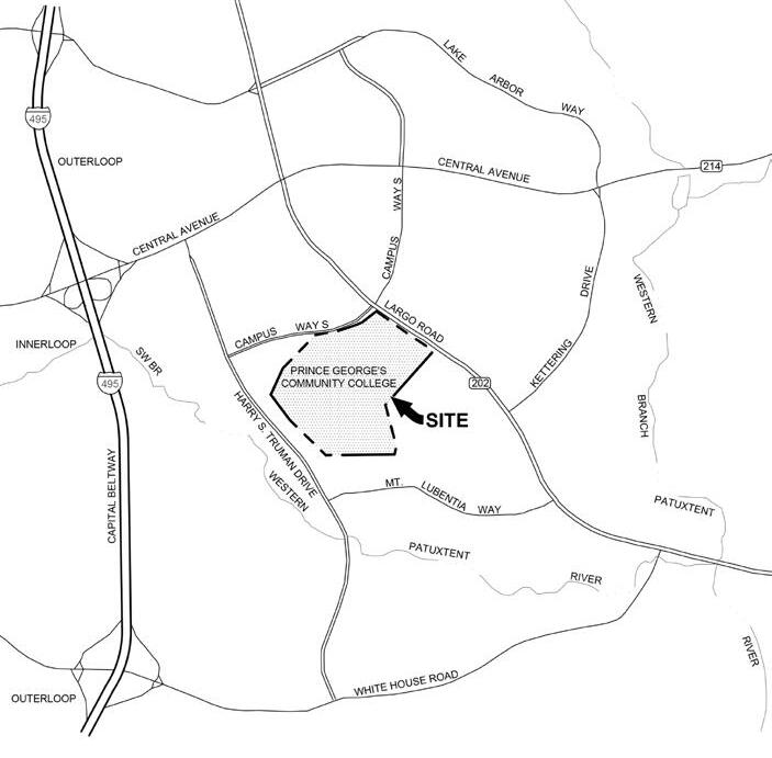
Bowie State University
Communication Arts and Humanities Building
UMCP Project #15‐669‐518‐00
100% Construction Documents
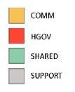

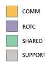
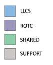
The following diagrams depict the spaces which are color coded by departmental. The organization is intended to create future flexibility as uses and departmental assignments change over the longer term, in addition to maximizing efficiency and shared use. The planning approach unites interior and exterior campus spaces to meet functional requirements and contribute to creating a dynamic campus character.


Bowie State University

Communication Arts and Humanities Building
UMCP Project #15‐669‐518‐00

100% Construction Documents


At Level 1, the northeast entry will be used most frequently by students arriving from campus and is adjacent to an existing parking lot.
Levels 2 and 3 share a consistent organizational approach, with academic departments and learning resources located in the west wing and active learning classrooms in the east wing.
Level 2 – Departments


The upper levels of the ‘heart’ connect these areas and contain open and enclosed distributed informal learning spaces. History and Government and Communications faculty and administration space are at Level 2, with ROTC and Language, Literature and Cultural Studies at Level 3.
Level 3 – Departments
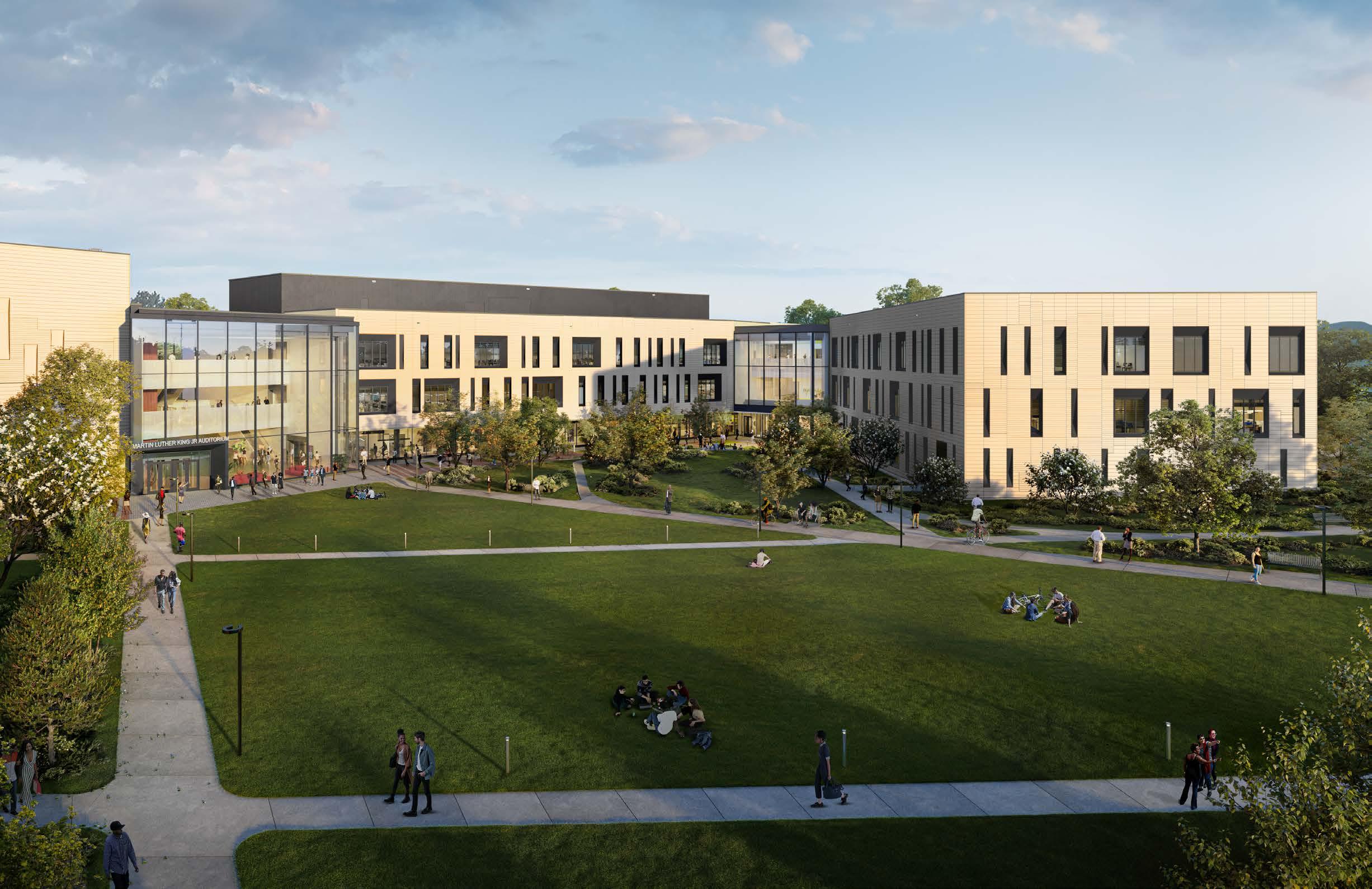
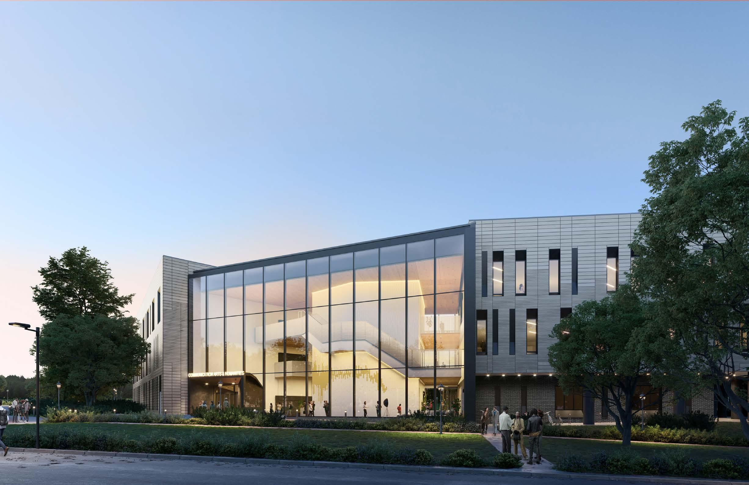
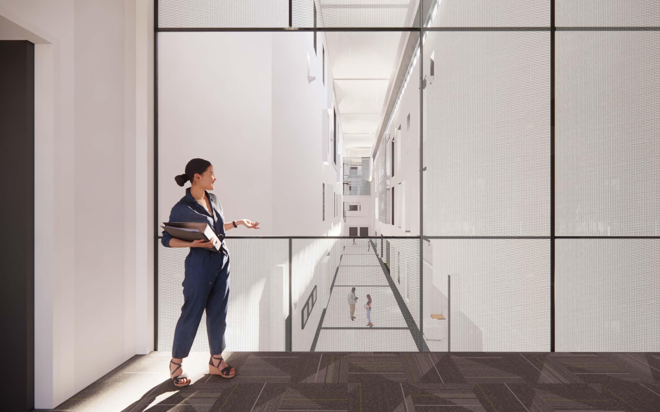
The auditorium, at the south end of the building, is visible and accessible to both the campus and community. The three-story glass facades of the student entrance, at the north, connects the campus to the building providing visual connection as well as access, on the ground floor, to the centrally located courtyard. Enjoy a welcoming and engaging environment.
The 1500-seat auditorium is iconic anchor at the south end of the building adjacent to the Loop Road and MARC rail station. The facade of the auditorium continues the patterning and movement of the typical facade with adjustments in scale, scope, and openings.


The new CAH Building will contain multiple departments and programs that are currently accommodated within the existing Martin King Jr. (MLK) Center which will be demolished once construction of the new building is complete. Project objectives include providing state-of-the art flexible and collaborative learning environments; specialized media production facilities, class laboratories, and departmental learning resources; faculty and administrative space to support interdisciplinary activity; and a 1500-seat assembly/auditorium space to serve a wide variety of BSU activities.
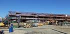
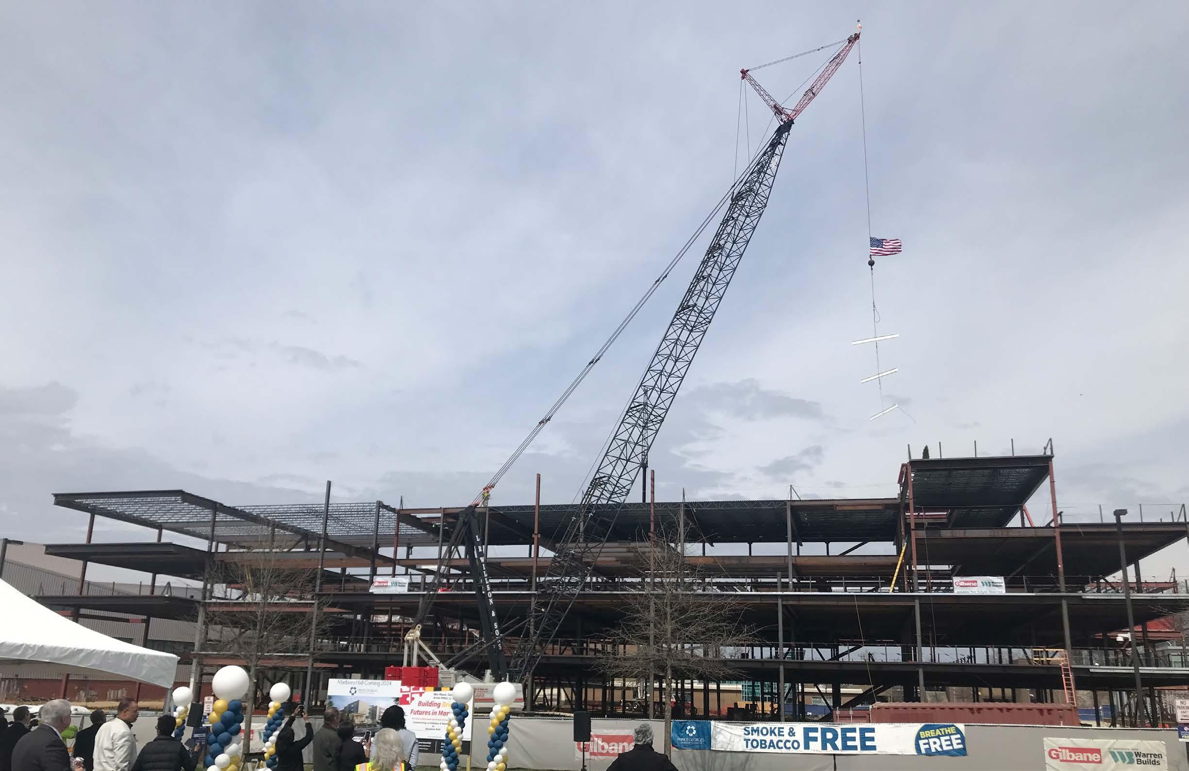
 CONSTRUCTION SITE PICTURE
CONSTRUCTION SITE PICTURE
CONSTRUCTION SITE PICTURE
Brief Description of Project
Size : 130,156 SF
College Maryland. 20774.
Design Start : 2018
Constructions Start : 2020
Setting : Academic
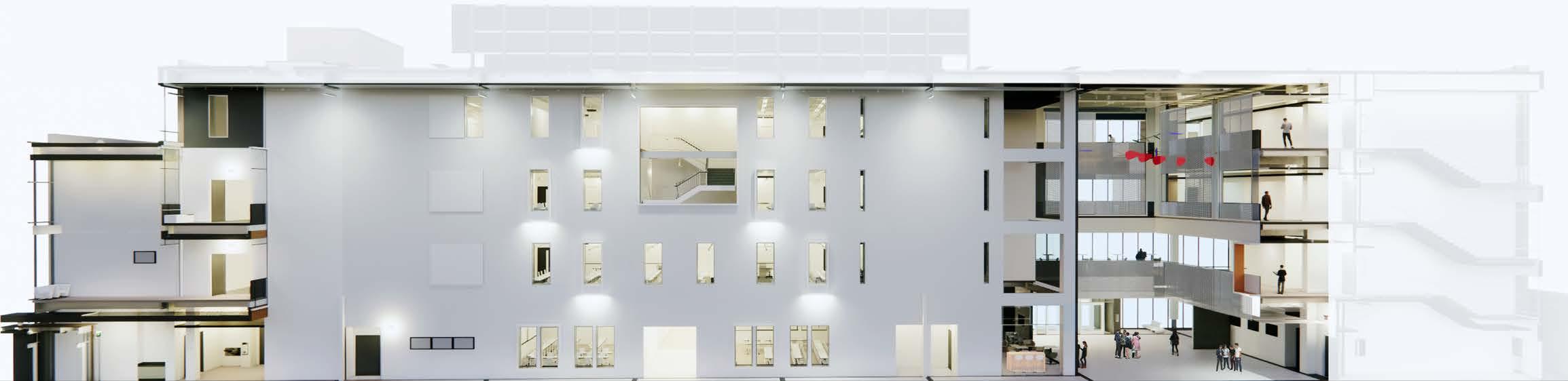
Marlboro Hall, originally built in the 1970’s, is a three-story building that will end up being doubled in size once the project is complete. The project included a full existing conditions study of the whole building, finding deficiencies in the superstructure, roofing, exterior walls, stairs, and windows and doors.

MC459
Department of General Services: ACTING SECRETARY: Atif T. Chaudhry
301 West Preston Street.
The renovations will provide the school with modern classrooms with new technology, more efficient MEP systems, and better accessibility measures. The 130,000 GSF renovated building will house laboratories for STEM departments, classrooms, offices, and study spaces. Additionally, work is being done to renovate several pedestrian bridges that connect Marlboro Hall to two other buildings on campus. Finally, the exterior of the building will be renovated and rebranded.
Understands the project and devises creative strategies to complete the work that meet or exceed the client’s expectations. Conducts research on existing building and campus infrastructure, coordinates field research, investigates and analyzes codes, produces site plans, floor plans, roof plans, demolition and phasing plans, and detailed elevations. Assists the Project Manager in providing overall architectural support throughout all phases of the project.
Baltimore. MD. 21201
DIAGRAMS - LEVELS 1,2,3,4


EXISTING: 40,056 GSF NEW: 33,578 GSF


Marlboro Hall will be designed to support and house the below programs, spaces, and occupants as shown:
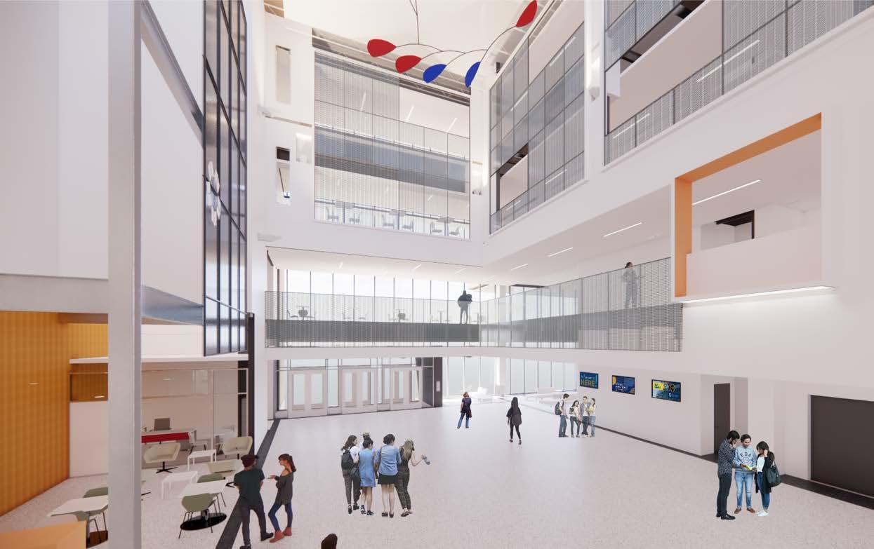
Table E.1-1: Floor Programming
Visual Arts Instruction (Classrooms/Labs)
Marlboro Hall Art Gallery
Art & Philosophy (Offices)
1st Floor
Veterans Services, PGCC Cares, Counseling Services (Offices and Supporting Spaces)
Weekend Office
Study Lounge and Study Space
English/History/Political Science/Geography/Anthropology Instruction (Classrooms/Labs)
Learning Foundations Learning Center & Labs
2nd Floor
Individual Study/Group Study Rooms
Conference Rooms
Non-assignable Lounge/Study Space
Mathematics, Teacher Education, Psychological/Sociological Instruction (Classrooms/Labs)
Mathematics Learning Center
3rd Floor
Individual Study/Group Study Rooms
Non-assignable Lounge/Study Space
Mathematics, Learning Foundations, Liberal Arts (excluding Art and Philosophy), and Social Sciences and Business (Offices)
4th Floor
Faculty Lounge/Professional Development Training Room
Conference Room
Marlboro Hall Renovation and Addition Part I and II Program Page 122
Renovate 77,672 NASF of space in Marlboro Hall and add an additional 72,719 NASF of space. The proposed solution will replace deteriorated building infrastructure components, correct extensive ADA issues, modernize finishes and equipment, and provide for expanded academic instruction in divisions such as Learning Foundations, Liberal Arts, Social Sciences and Business and STEM. Transforming the outdated and undersized Marlboro Hall building to a modern instructional classroom and lab building will create a synergy for students and faculty currently missing in the current building.


KPN was Architect of Record and Prime Consultant for the project. Our scope included researching the existing building and campus infrastructure, field research, code analysis, and production of demolition and phasing plans and specifications. KPN conducted extensive document reviews and interviews of College personnel to ensure that the demolition documents were based on the best possible information. Laser scanning was conducted to produce a point cloud model of the existing building, including MEP services, and a utility locator was contracted to locate utilities for which there was insufficient documentation. A complete team of consultants was utilized to investigate the existing conditions and produce the demolition documentation, including in addition to the above an envelope consultant, a hazmat consultant, civil engineer, structural engineer, MEP engineer, and geotechnical consultant.
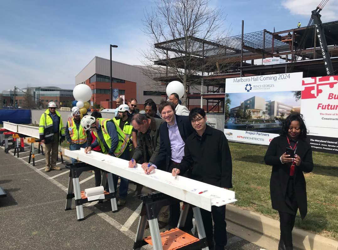 CONSTRUCTION SITE PICTURE
Size : 7.5 Acres
Design Start : 2017
Constructions Start : 2021( est.)
Setting : Mixed Use
The redevelopment of Rash Field, located adjacent to Baltimore’s Inner Harbor,is expected to draw more visitors to the area and generate revenue for the city. The rejuvenated park will enhance recreation options for users, create a gateway to the waterfront promenade from the surrounding neighborhood, and contribute to the broader vision for the Inner Harbor.

KPN is the Architect of Record working with a site designer, Mahan Rykiel Associates, for the overall park.
KPN’s responsibility includes the architectural work associated with the park improvements, incorporating a retail pavilion and public facilities inserted into the landscape with a green roof wrapping over the top of the structure.
Responsibility
Responsible for architectural documentation, Revit modeling and coordination with consultants, and complete CA services.
Based on the approved Design Development documents, I assisted the project manager in preparing Construction Documents consisting of drawings and specifications that described the scope of construction work. These documents were suitable for filing with the Building Department and for use in construction by a qualified General Contractor.

Attend project coordination meetings, visit the project site at biweekly intervals when work relevant to our scope is underway as appropriate to monitor the progress of the work and determine whether the work is in accordance with the Construction Documents. contribute to the broader vision for the Inner Harbor.
Rash Field, located along the waterfront promenade, has the potential to become the vibrant heart of the Inner Harbor, drawing families and visitors from both the city and the wider region to enjoy a welcoming and engaging environment.

Rash Field opened to the public in November 2021 and saw a remarkable increase in visitation, with an average of 1500 visitors per day. Surveys indicate that visitors are coming not only from the local area but also from the wider region who discover the park during their travels.

Size : 25+ Acre
Design Start : 2021
Constructions Start : 2023
Setting : Mixed -use, Residential
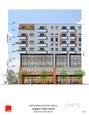
The 25+ acre site is located across Wabash Avenue from the Reisterstown Transit Station. There is a pedestrian bridge that connects this site to the station. The project is conceived as a compact, transit-oriented development that will maximize access to the MTA Reisterstown Plaza Metro stop. Wabash Town Center will incorporate various sustainable design elements to minimize negative environmental impact through skillful, sensitive design. The master plan development schedule is extended over 4 phases. Each phase develops one of the quadrants of the site. Phase 1 is located on the location of the 2 existing surface parking lots located along Wabash Avenue across from the metro train station and bus stop. The proposed plan is to divide Phase 1 into two Sub-Phases 1A and 1B. Phase 1A located in TOD 4 will be built first, up to an allowable height of 100’. Phase 1B located in TOD 3 will follow, and will be built up to the allowable height of 60’.

Responsibility
Develop schematic design drawings for residential, mixed-use, and commercial buildings at different phases of this project. Prepare graphic materials and designs for studies and/or presentations to the client. Develop design concepts, narratives, Revit models, 3D renderings, plans, sections, exterior elevations, and virtual reality presentations, as necessary, to effectively convey the design intent to clients.
The comprehensive redevelopment of this Transit Oriented Development (TOD) site will be completed in phases.
Phase 1A: 272 apartment units, 7 retail spaces (37,287 SF), 24,970 SF of office and 555 parking spaces.

Phase 1B: 112 apartment units, 7 retail spaces (28,210 SF), 21,503 SF of office and 354 parking spaces.
Phase 2A: Intergenerational townhouses – 40 units with a community center and 43 offstreet parking spaces
Phase 2B: 42 units senior living apartments, 163 off-street parking spaces and common area. This common area may include a bistro, which is primarily for the use of the tenants.
Phase 3: Developing the natural site along the south east edge of the site adjacent to the Social Security Campus would be Phase 3 or the Arts and Green Phase in this community.

Phase 4: Medical and Health Care hub including offices, urgent care, health and fitness, nursing home/rehabilitation center and accessory retail. The total number of parking spaces is to be determined.
The building, each in Phase 1A and 1B are programmed as mixed use. They include retail, parking, offices and market rate apartments. Both buildings will be joined at the ground level to maximize the need for additional parking.
Two buildings, Phase 1A and 1B, will be constructed in the highest-density portion of the site and are programmed as mixed use. These properties include retail, parking, offices and market rate apartments. (Please see plan and Section) These buildings, with a total of apartment units, are the heart and anchor of the new community and are designed to take full advantage of the transit access.
These properties create the density to support retail and amenities - and a center point for the neighborhood as a whole.


The Market data indicate there is a high-demand, for quality, apartment living with good transit (and highway) access in this portion of Baltimore City and County. Units will be highly contemporary in design, capable of supporting the latest in tech accommodating the mixed of transit-based AND work-from-home lifestyles that are in demand in the post-COVID era.


Designed around the concepts developed by Carehous (carehous.net), this building will be housing for a senior population with living units for their caregivers. Carehaus’s work is founded on the belief that older adults, disabled people, and those who care for them are integral to the well-being of these senior communities. Communal spaces will be designed to encourage interaction between seniors and their caregivers through various programs.
This phase proposes 42 units of senior (age-restricted) multi-family housing units, 163 offstreet parking spaces and accessory common areas including a small bistro. The non-residential uses are intended for primary use by the residents.


Size : 168,000 SF
Design Start : 2017
Constructions Start : 2021
Setting : K-12 Education
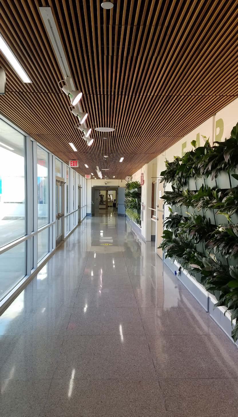
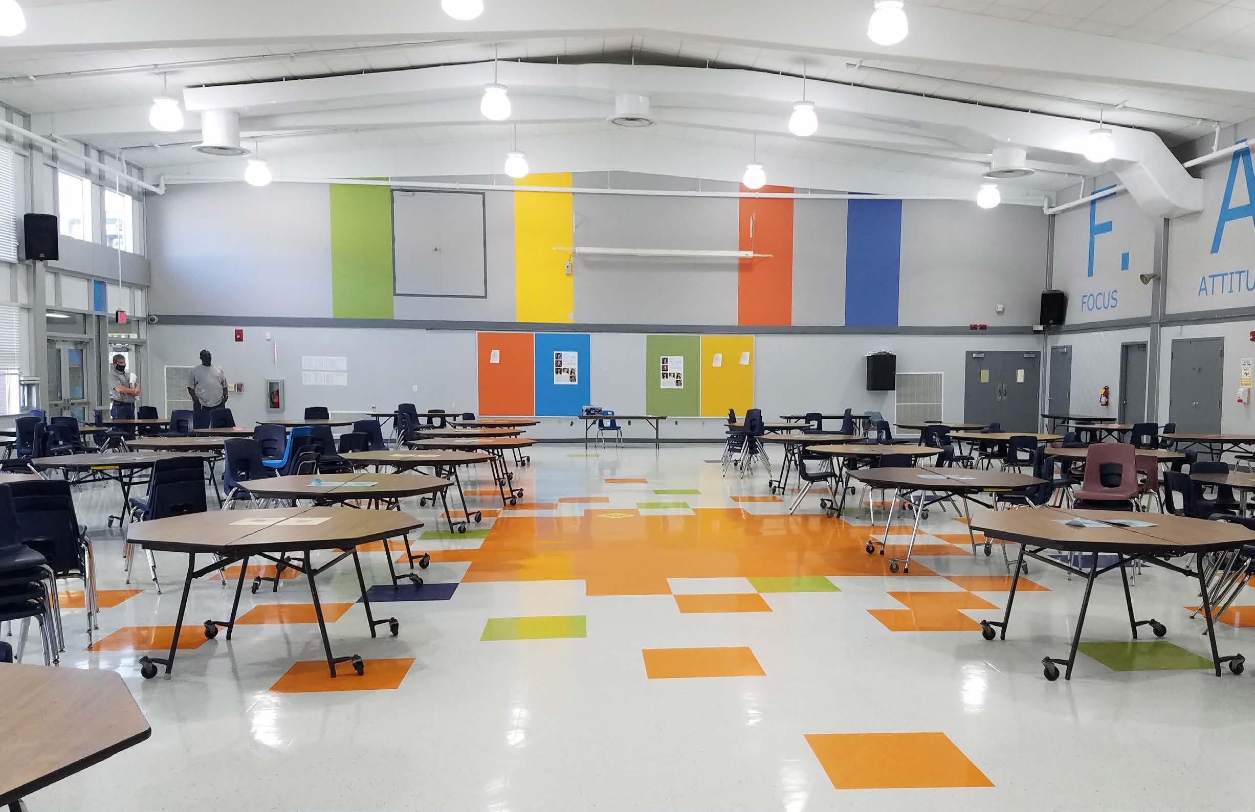
Central High School is a 168,000 gsf masonry building originally built in 1960 with major additions constructed in 1983, 1989, and 2003. The project included in Phase 1, the complete replacement of (1) the entire HVAC system and in Phase 2 all exterior windows and storefront systems. The new HVAC system for the Central High School has VAV air distribution with Series Fan-Powered VAV Terminal Boxes served by central station air handling units for classrooms, offices, and media center. The new HVAC system should be designed to maintain slight positive building pressure at all times, including off-hours. The project later included in Phase 3 the complete interior rebranding of the school. The school was to get new interior finishes and exterior finishes that remained to be patched and repaired.
Designing an interior design concept for the entire school. Prepared finish boards and materials and coordinated the re branding scheme with the earlier phases that included renovation of HVAC systems and replacement of all windows and aluminum curtainwall systems.
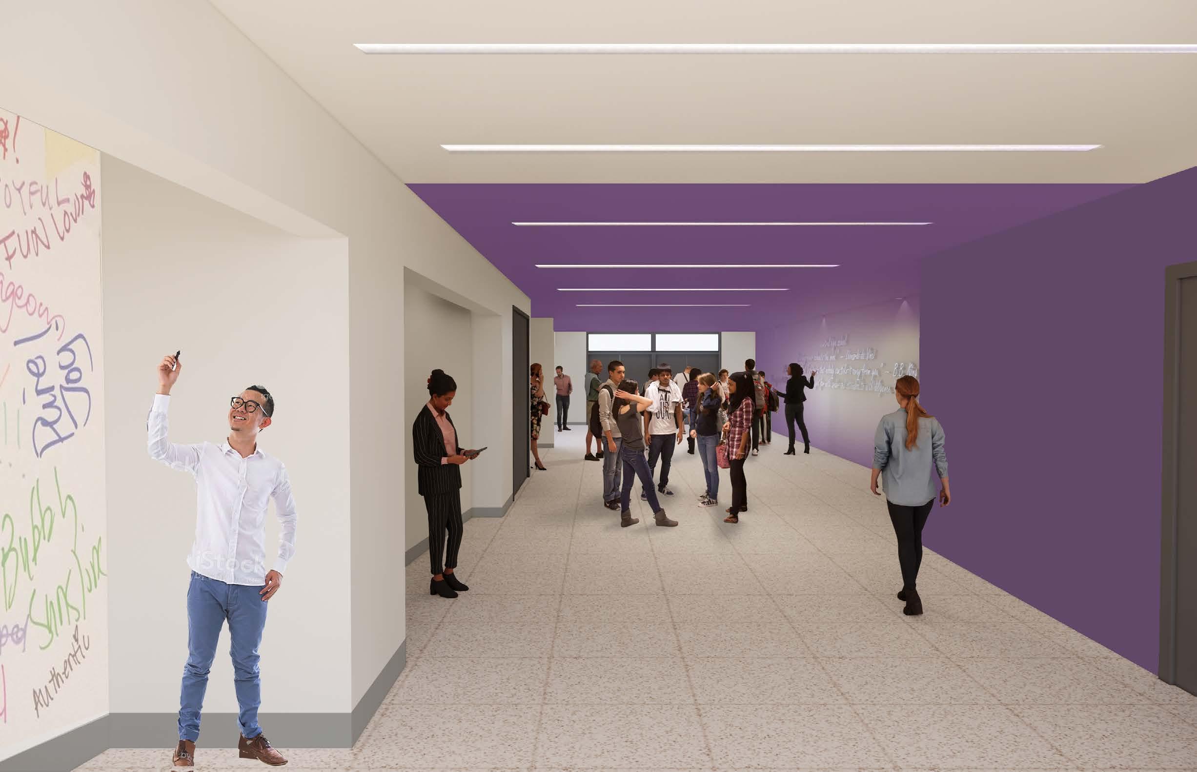
The rebranding theme included replacement of chalkboards with marker boards and smart boards, improved daylighting in learning spaces, use of sustainable materials. The central theme was to activate the common areas and hallways with areas for collaboration, display and presentations
CORRIDOR #1 - INTERIOR LIVING WALL ELEVATION
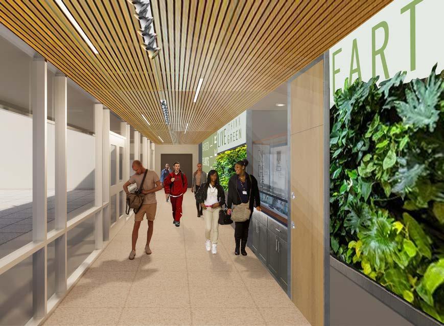
INSPIRATION WALL 301 SUPERGRAPHIC WALL 308
SCALE: 1/4" = 1'-0"


1.ANYWHERE "HVAC REPLACEMENT DRAWINGS" ARE REFERRED TO IN THESE DRAWINGS, IT REFERS TO THE PHASE 1& 2 CENTRAL HIGH SCHOOL HVAC REPLACEMENT AND BUILDING MODERNIZATION PROJECT THAT PRECEDES THE PHASE 3 BRANDING RENOVATION.
2.THERE ARE EIGHT (8) BUILDING AREAS WITH DIFFERENT FINISH COLOR THEMES. REFER OVERALL PLAN FOR BUILDING AREAS. REFER AREA PLANS FOR COLOR THEME. FIELD VERIFY EXISTING CONDITIONS FOR PRICING AND QUANTITIES.


3.EACH ROOM IS DESIGNATED BY A ROOM TYPE ON THE AREA PLAN. ROOM TYPE DETERMINES SCOPE OF WORK.

4.EXISTING CMU BLOCK PIERS AND STEEL TUBE COLUMNS ARE SHOWN IN TYPICAL CLASSROOM ELEVATIONS TO PROVIDE INSTRUCTION ON TYPICAL TREATMENT. THESE BUILDING ELEMENTS ARE NOT PRESENT IN ALL CLASSROOMS.
5.INFORMATION SHOWN ON THE DRAWINGS PERTAINING TO EXISTING CONDITIONS HAS BEEN OBTAINED FROM AVAILABLE BUILDING DRAWINGS OR GENERAL FIELD OBSERVATIONS AND MAY NOT INDICATE ACTUAL EXISTING CONDITIONS IN DETAIL OR DIMENSION. THE CONTRACTOR IS RESPONSIBLE FOR DETERMINING ACTUAL EXISTING CONDITIONS PRIOR TO PRICING AND PERFORMANCE OF ANY WORK. SHOULD CONDITIONS BE DISCOVERED THAT PREVENT EXECUTION OF THE WORK AS INDICATED OR THAT DO NOT MATCH DOCUMENTS, THE CONTRACTOR SHALL IMMEDIATELY NOTIFY THE ARCHITECT IN WRITING AND AWAIT DIRECTION BEFORE PROCEEDING WITH WORK. COORDINATE DOCUMENTS FOR PHASE 1, 2 & 3 WORK DURING PRICING.
6.COORDINATE TESTING AND ABATEMENT OF HAZARDOUS MATERIAL WITH SCHOOL SYSTEM FOR EACH PHASE OF WORK.
7.ALL FLOOR, CEILING AND WALL MOUNTED DEVICES, FIXTURES AND ASSOCIATED BLOCKING THAT MUST BE REMOVED FOR WORK MUST BE REINSTALLED AND MADE OPERATIONAL. UNLESS OTHERWISE INDICATED. BLOCKING AND APPURTENANCES NO LONGER REQUIRED ARE TO BE REMOVED AND WALL PATCHED AND FINISHED TO MATCH SURROUNDING. NEW BLOCKING TO BE INSTALLED FOR SUPPORTS FOR FUTURE INTERACTIVE SMART BOARD INSTALLATION.
8.HVAC RENOVATION WORK TO BE COORDINATED WITH BRANDING RENOVATION.
9.PATCH AND REPAIR EXISTING GYPSUM BOARD WALLS PRIOR TO PAINTING. ESTIMATE 15% OF EXISTING GYPSUM BOARD WALLS TO BE REPLACED WITH NEW GYPSUM BOARD. INCLUDE ALLOWANCE OF 15% OF TOTAL COST. THIS DOES NOT INCLUDE LOCATIONS FOR BLOCKING FOR INTERACTIVE SMART BOARDS.
10.PATCH AND REPAIR EXISTING CMU MASONRY WALLS PRIOR TO PAINTING. ESTIMATE 80% OF MASONRY WALLS TO BE UNPAINTED GLAZED BLOCK AND 20% OF MASONRY WALLS TO BE UNGLAZED BLOCK.
11.REPAIR CRACKS IN EXISTING TERRAZZO PRIOR TO CLEANING TERRAZZO. ESTIMATE 10% OF EXISTING TERRAZZO TO BE CRACKED. INCLUDE ALLOWANCE OF $10,000.
12.FOR ALL AREAS WHERE NEW RESILIENT FLOORING IS TO BE INSTALLED, PATCH AND REPAIR FLOORING AFTER REMOVAL OF EXISTING FLOOR FINISH AND PRIOR TO APPLICATION OF NEW FLOOR FINISH. PREPARE SUBFLOOR FOR NEW FLOOR FINISH PER MANUFACTURER'S INSTRUCTIONS. COORDINATE HAZARDOUS MATERIAL REMOVAL TO MEET SCHOOL SYSTEM REQUIREMENTS.
13.GENERAL WAYFINDING SIGNS TO BE LEFT AS IS.
1.ANYWHERE "HVAC REPLACEMENT DRAWINGS" ARE REFERRED TO IN THESE DRAWINGS, IT REFERS TO THE PHASE 1& 2 CENTRAL HIGH SCHOOL HVAC REPLACEMENT AND BUILDING MODERNIZATION PROJECT THAT PRECEDES THE PHASE 3 BRANDING RENOVATION.
2.THERE ARE EIGHT (8) BUILDING AREAS WITH DIFFERENT FINISH COLOR THEMES. REFER OVERALL PLAN FOR BUILDING AREAS. REFER AREA PLANS FOR COLOR THEME. FIELD VERIFY EXISTING CONDITIONS FOR PRICING AND QUANTITIES.
3.EACH ROOM IS DESIGNATED BY A ROOM TYPE ON THE AREA PLAN. ROOM TYPE DETERMINES SCOPE OF WORK.
4.EXISTING CMU BLOCK PIERS AND STEEL TUBE COLUMNS ARE SHOWN IN TYPICAL CLASSROOM ELEVATIONS TO PROVIDE INSTRUCTION ON TYPICAL TREATMENT. THESE BUILDING ELEMENTS ARE NOT PRESENT IN ALL CLASSROOMS.
5.INFORMATION SHOWN ON THE DRAWINGS PERTAINING TO EXISTING CONDITIONS HAS BEEN OBTAINED FROM AVAILABLE BUILDING DRAWINGS OR GENERAL FIELD OBSERVATIONS AND MAY NOT INDICATE ACTUAL EXISTING CONDITIONS IN DETAIL OR DIMENSION. THE CONTRACTOR IS RESPONSIBLE FOR DETERMINING ACTUAL EXISTING CONDITIONS PRIOR TO PRICING AND PERFORMANCE OF ANY WORK. SHOULD CONDITIONS BE DISCOVERED THAT PREVENT EXECUTION OF THE WORK AS INDICATED OR THAT DO NOT MATCH DOCUMENTS, THE CONTRACTOR SHALL IMMEDIATELY NOTIFY THE ARCHITECT IN WRITING AND AWAIT DIRECTION BEFORE PROCEEDING WITH WORK. COORDINATE DOCUMENTS FOR PHASE 1, 2 & 3 WORK DURING PRICING.
6.COORDINATE TESTING AND ABATEMENT OF HAZARDOUS MATERIAL WITH SCHOOL SYSTEM FOR EACH PHASE OF WORK.
7.ALL FLOOR, CEILING AND WALL MOUNTED DEVICES, FIXTURES AND ASSOCIATED BLOCKING THAT MUST BE REMOVED FOR WORK MUST BE REINSTALLED AND MADE OPERATIONAL. UNLESS OTHERWISE INDICATED. BLOCKING AND APPURTENANCES NO LONGER REQUIRED ARE TO BE REMOVED AND WALL PATCHED AND FINISHED TO MATCH SURROUNDING. NEW BLOCKING TO BE INSTALLED FOR SUPPORTS FOR FUTURE INTERACTIVE SMART BOARD INSTALLATION.
8.HVAC RENOVATION WORK TO BE COORDINATED WITH BRANDING RENOVATION.
9.PATCH AND REPAIR EXISTING GYPSUM BOARD WALLS PRIOR TO PAINTING. ESTIMATE 15% OF EXISTING GYPSUM BOARD WALLS TO BE REPLACED WITH NEW GYPSUM BOARD. INCLUDE ALLOWANCE OF 15% OF TOTAL COST. THIS DOES NOT INCLUDE LOCATIONS FOR BLOCKING FOR INTERACTIVE SMART BOARDS.
10.PATCH AND REPAIR EXISTING CMU MASONRY WALLS PRIOR TO PAINTING. ESTIMATE 80% OF MASONRY WALLS TO BE UNPAINTED GLAZED BLOCK AND 20% OF MASONRY WALLS TO BE UNGLAZED BLOCK.
11.REPAIR CRACKS IN EXISTING TERRAZZO PRIOR TO CLEANING TERRAZZO. ESTIMATE 10% OF EXISTING TERRAZZO TO BE CRACKED. INCLUDE ALLOWANCE OF $10,000.
12.FOR ALL AREAS WHERE NEW RESILIENT FLOORING IS TO BE INSTALLED, PATCH AND REPAIR FLOORING AFTER REMOVAL OF EXISTING FLOOR FINISH AND PRIOR TO APPLICATION OF NEW FLOOR FINISH. PREPARE SUBFLOOR FOR NEW FLOOR FINISH PER MANUFACTURER'S INSTRUCTIONS. COORDINATE HAZARDOUS MATERIAL REMOVAL TO MEET SCHOOL SYSTEM REQUIREMENTS.
13.GENERAL WAYFINDING SIGNS TO BE LEFT AS IS.
KEYNOTES BY ROOM TYPE: REFER A-002.
1
MULTIPURPOSE ROOM - INTERIOR ELEVATION
ROOM – INTERIOR ELEVATION
2 SCALE: MULTIPURPOSE ROOM - INTERIOR ELEVATION


SCALE: MULTIPURPOSE ROOM - INTERIOR ELEVATION
MULTIPURPOSE ROOM – INTERIOR ELEVATION

Size : 20+ Acre
Design Start : 2017
Setting :Residential
The architectural standards proposed for the multifamily structures create a dynamic, cohesive and harmonious fit within the project as well as the overall community. The multifamily clusters are made up of “L” shaped buildings. The buildings act as a backdrop to the pedestrian and vehicular street patterns reinforcing and activating the space with building elements such as the outdoor balconies. The building configurations somewaht enclose the surface parking to aid in the screening of the parking from public view.
The exterior building material and color selctions were chosen based on their compatibility with the other residential building types within the project as well as the surrounding community. Permanence and sustainability were other key factors in the selection of the exterior materials.
Develop schematic design drawings for residential buildings at different phases of this project. Prepare graphic materials and designs for studies and/or presentations to the client. Develop design concepts, narratives, Revit models, 3D renderings, plans, sections, exterior elevations, and virtual reality presentations, as necessary, to effectively convey the design intent to clients.
10/12/2018


Architecture
Multi-Family Building
SCHEMATIC FRONT ELEVATION
SCHEMATIC

SCHEMATIC FRONT ELEVATION


Size : 100,000sf

Design Start : 2015
Constructions Start : 2017
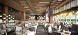
Setting : Hospitality + Sport › Hotel Restaurant Sports Center Wellness/Spa

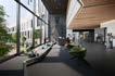
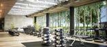
DMAC’s bold and progressive design for the new expansion of Midtown Athletic club seeks to create a new statement and revitalize the stretch of Elston Ave. creating an exciting and vibrant ‘Midtown Corridor’, acting as a beacon to the City’s premier Athletic Club. The project includes a 100,000sf expansion to their facility, to include multiple swimming pools, progressive fitness areas, spinning, yoga & pilates studios, lockers rooms, spa and a 3000 sf restaurant. The new design that also has a 25,000 outdoor pool deck would provide dramatic views of the city and integrate green design elements like roof gardens and vegetation.
Responsibility
Assists senior staff in verifying site details to support the design. Works with the project manager and project designer in creating buildings that serve the client’s needs and respond to their desired image, space, and aesthetic.


Size : 42-floor, 168-meter (551 ft) tall
Design Start : 2015
Constructions Start : 2016
Setting : Mixed -use skyscraper
Kula Belgrade is a 42-floor, 168-meter tall mixed-use skyscraper located in the Belgrade Waterfront on the bank of the Sava River, becoming the tallest building in the country. The tower will have a direct approach to a waterfront promenade, located in close proximity to Belgrade Fortress.
The tower, combining residential, commercial, hospitality and entertainment offerings, is made of concrete presenting steel structures on the podium on the ground floor, on secondary structures supporting the façade and on the top crown located on the top of the tower and developing for its last three floors.
The Kula Belgrade tower is the new landmark of the Serbian capital and is part of the 1.8 million square metre Belgrade Waterfront development, featuring world-class residences and offices, hotels, educational institutions, modern healthcare amenities, as well as a 1.8-kilometre long public waterfront edge and public parks.

Responsibility
Preparation of accurate architectural presentations, designs, details, and construction documents in REVIT, including plans, exterior elevations, and interior details.

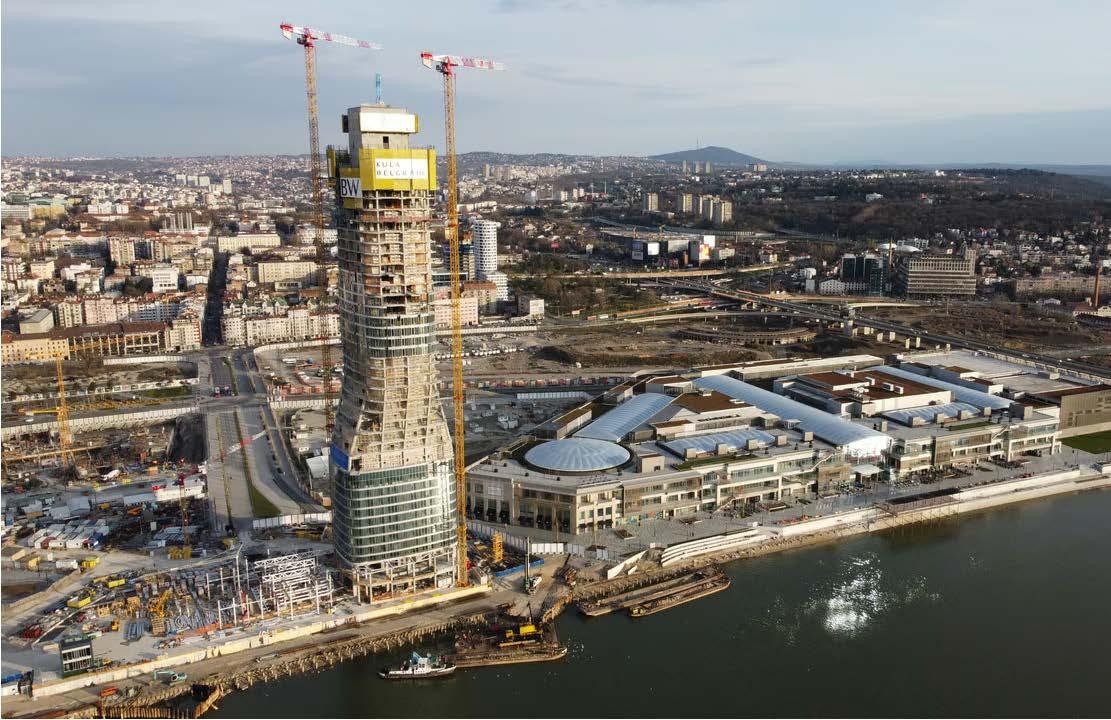
Note: As this project is under construction, the data is based on the most reliable information currently available.
Official Name Kula Belgrade
Name of Complex Belgrade Waterfront
Structure Type Building
Status Under Construction
Country Serbia
City Belgrade
Building Function Residential / Hotel
Proposed 2015
Construction Start 2016
Height: Architectural 168 m / 551 ft
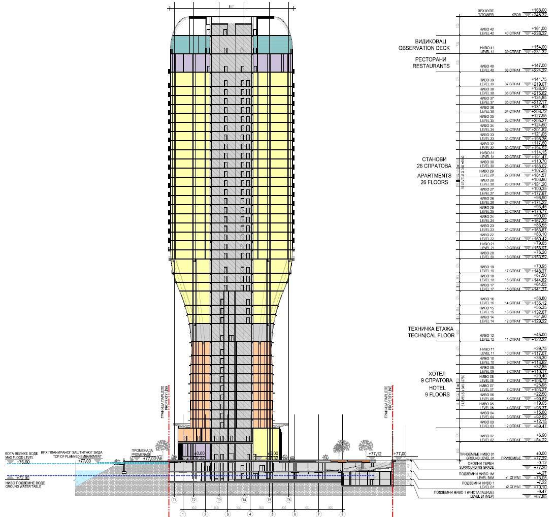
Floors Above Ground 42
Tower GFA 47,000 m² / 505,904 ft²
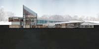
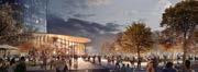
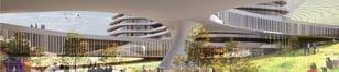
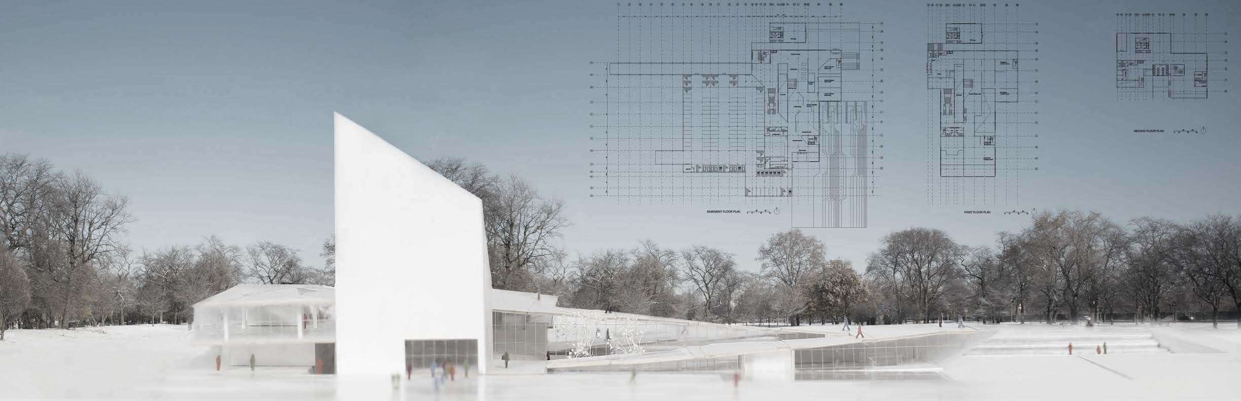
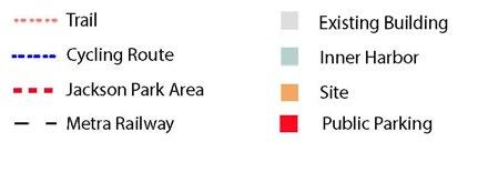
The Barack Obama Foundation recently issued an RFP proposing a new standard for Presidential Libraries. Differentiating itself from other Presidential Libraries, I design will create an innovative place of engagement and vibrant community hub.
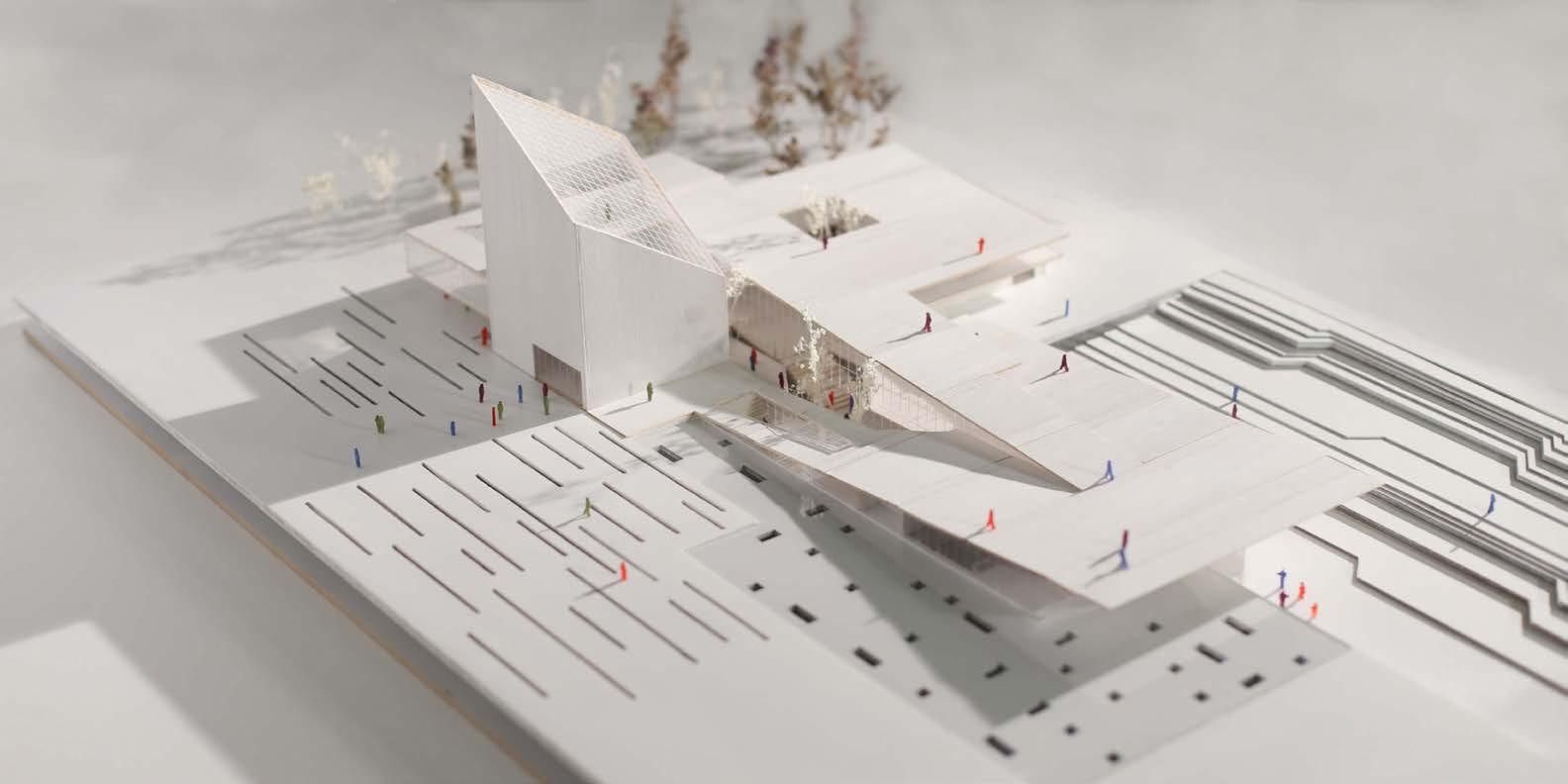
The building will be multi-level new construction not to exceed 70,000SF. The site will also include significant public space connections to public transportation and commu nity thoroughfares.

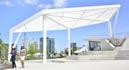
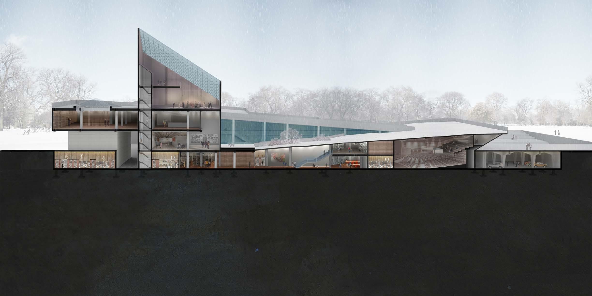
The different sizes of rectangles and squares cavities on the walkways are designed to create different lighting effects during different times of the day. At day time, the sun will create skylights down into the parking garage. At night, the lights in the parking garage will illuminate the walkways from below.


The glass and steel are the predominant materials of the projects and the underground parking are complemented with concrete and steel structure.The structure of underground parking garage is directly related to the design of the aboveground walkways. The “Y” columns support are made with steel and concrete.


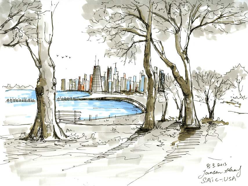
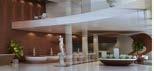
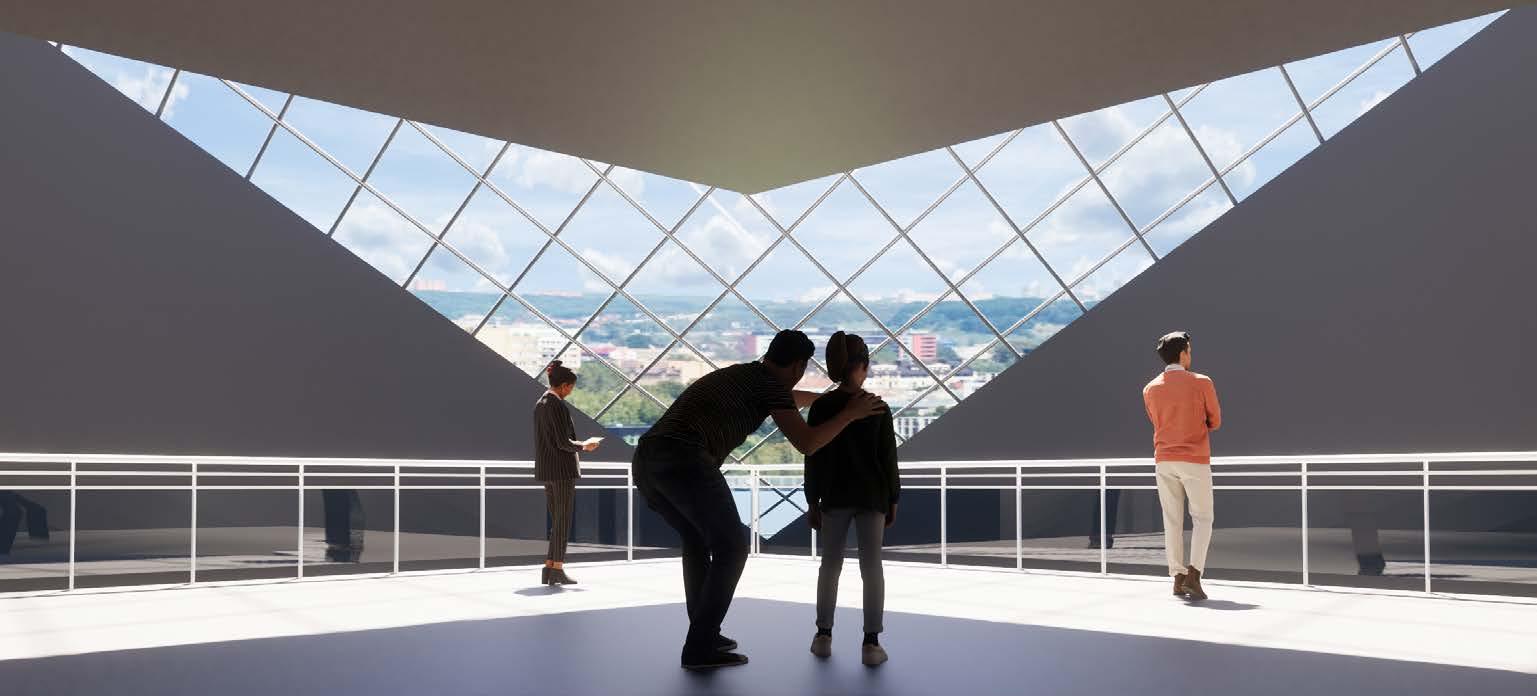
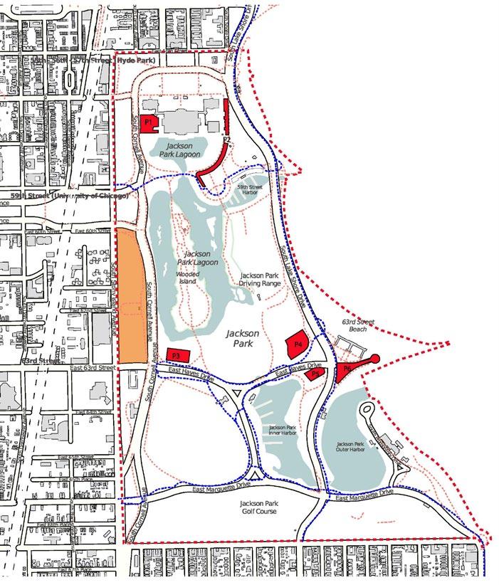
The Museum’s Sky Room, located at the highest point, provides an opportunity for visitors to contemplate while enjoying breathtaking panoramic views of Lake Michigan towards the East, downtown Chicago’s towering skyscrapers in the North, and the West and South sides of Chicago.
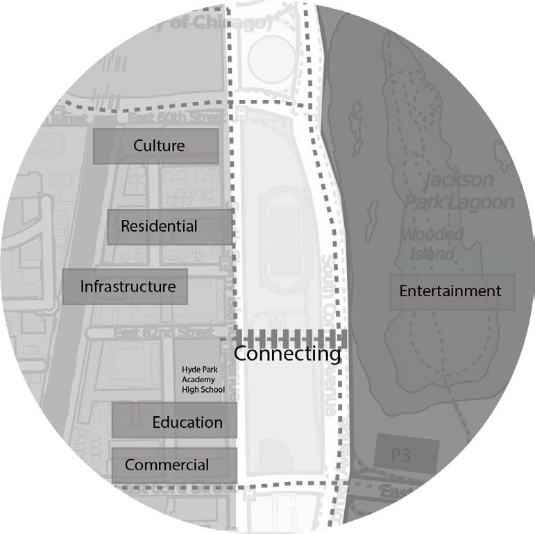
This library serves as a bridge of education to business and social interaction; and potentially acts as a model that not only reshapes the site and surrounding neighborhood, but also the concept of what a Presidential Library can be in the future.

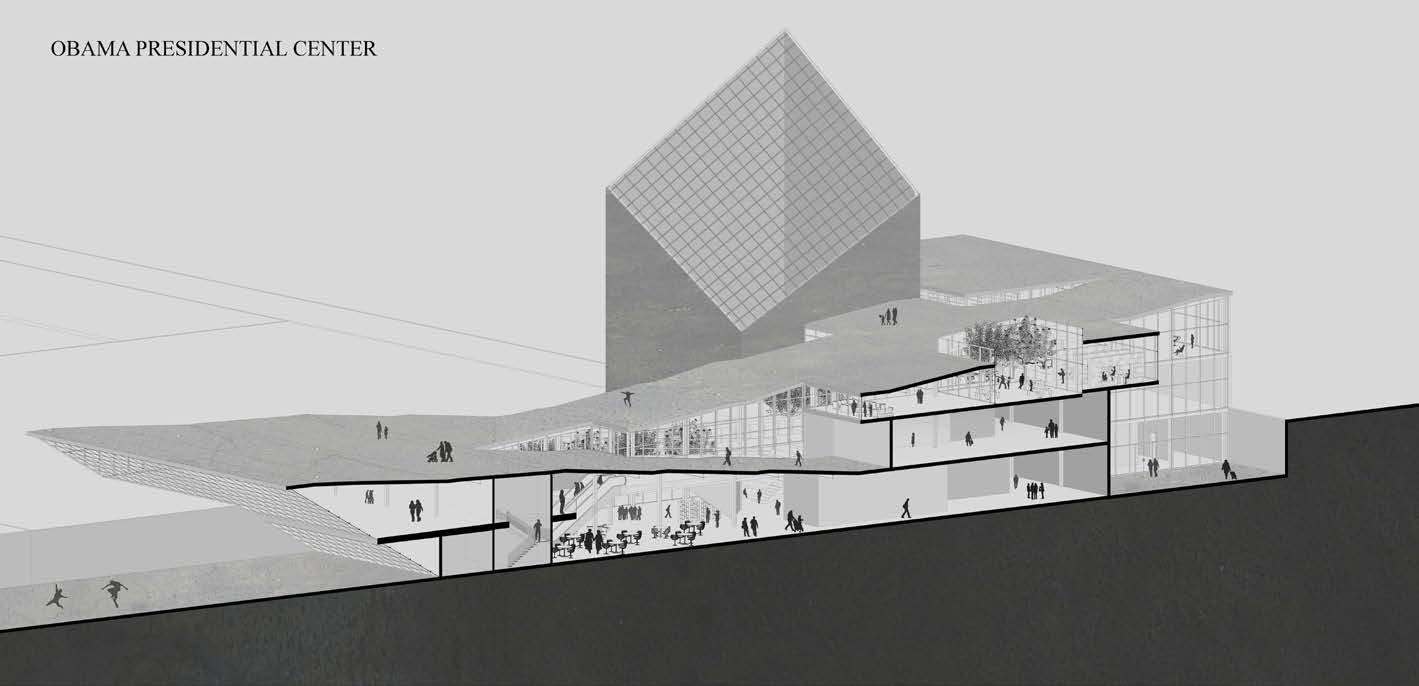
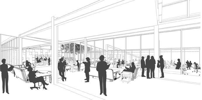
Natural light creates a connection between the interior and exterior spaces.
The library’s interior space has been meticulously crafted with a stepped design that progressively widens the view as one ascends the floors, facilitating an interactive relationship between individuals and the interplay of space, light, and surrounding scenery.

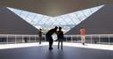
The diamond-shaped roof design of the main library building not only allows natural light to illuminate the interior space but also offers a magnificent view of Jackson Park’s picturesque scenery.

The new Museum building in the South Side will serve as a significant landmark, inviting visitors to Jackson Park and highlighting the Center as a historical civic hub. The design of the Museum embodies the concept of upward movement from the grassroots.

The forthcoming Chicago Public Library branch will present interactive digital media zones and child-friendly amenities, informative and vocational resources for adults, and a reading room open for everyone to relish. This exceptional collaboration is a pioneer in its category and will furnish almost all residents of the South Side with nearby public library access, with a walking distance.

The courtyard, in the center of a building, allows natural light to flow into the surrounding interior spaces, creating a brighter and more inviting atmosphere. Additionally, the design of the courtyard can provide a visual and physical connection between different levels or sections of the building, encouraging exploration and movement throughout the space. This dynamic and interconnected layout can create a more engaging and lively environment for visitors.


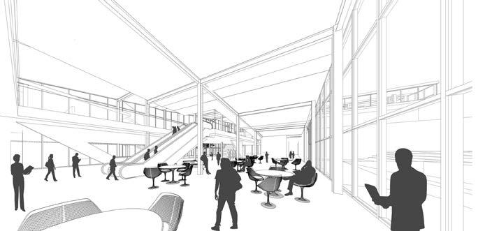
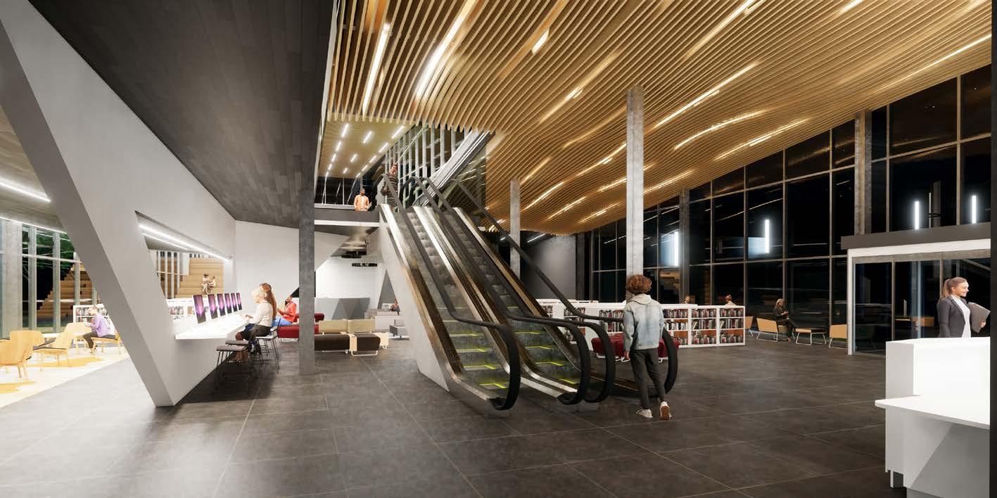
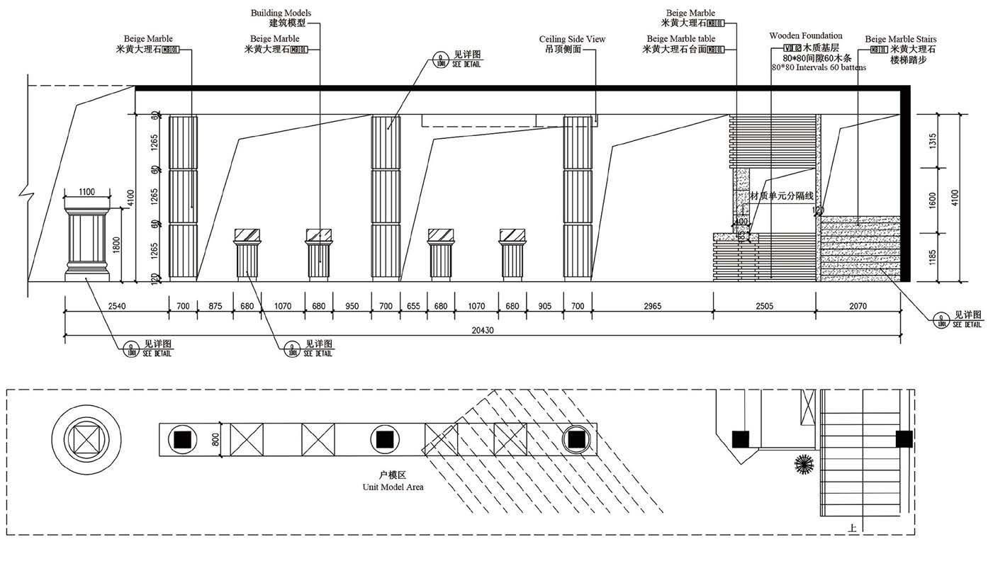
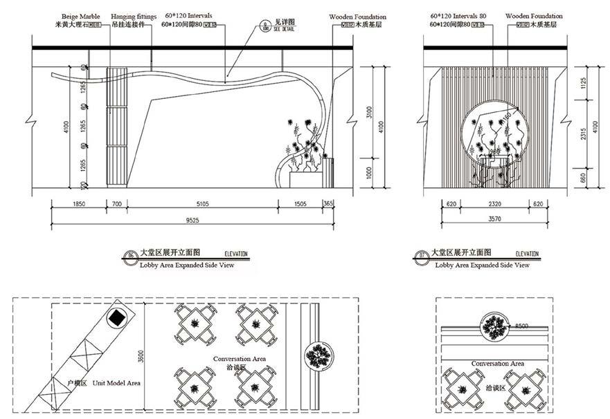
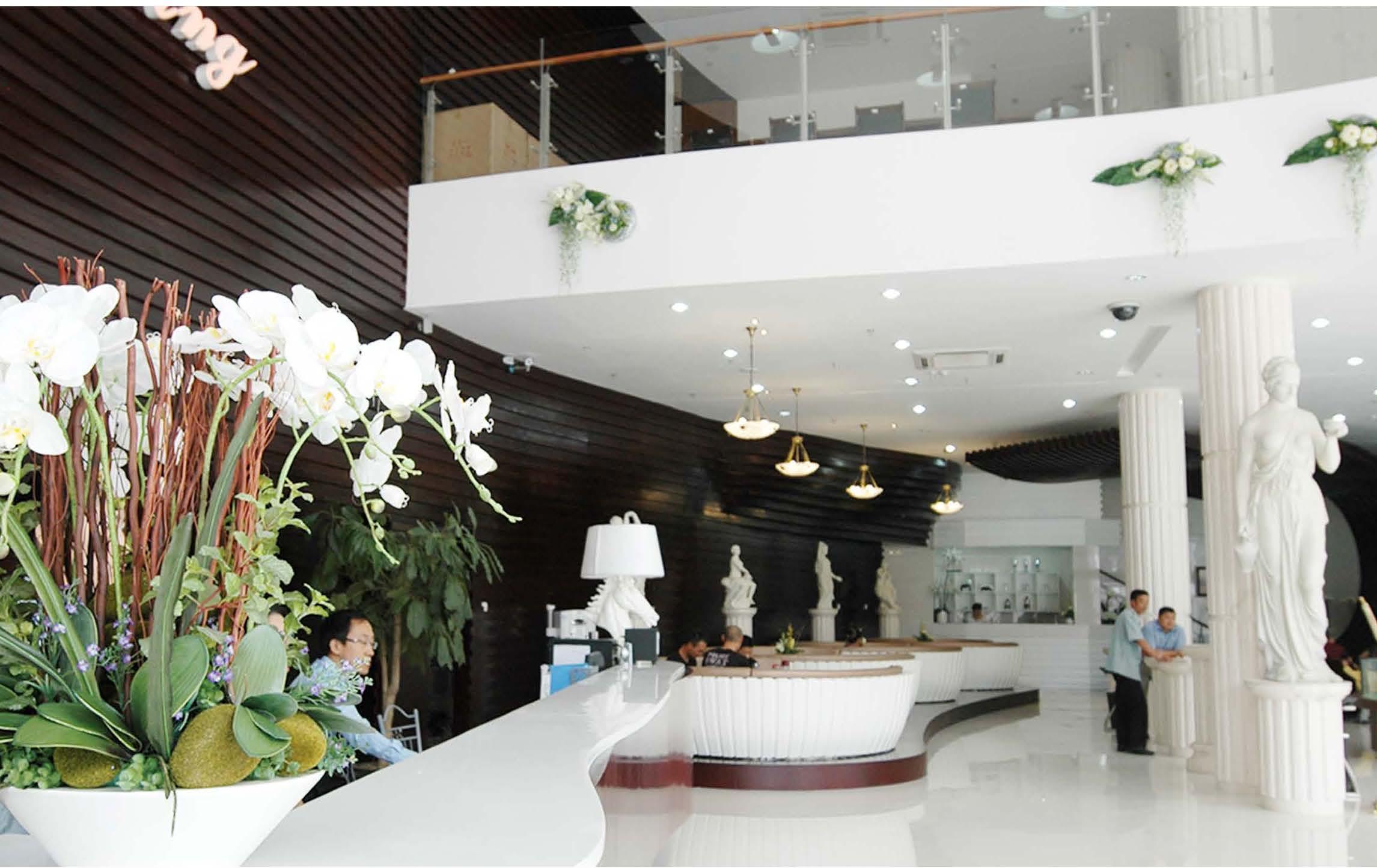
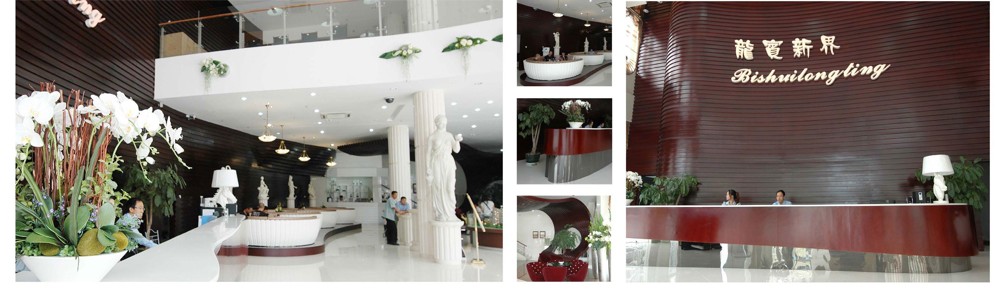
Lianjian is a suburban county on the eastern coast of Fujian province, China. Due to its abundant amount of wet land resources in the Ming Jing River, Liangjian is flourished with rich fish resources. Not only does this contribute to economic growth, it further allows industries to develop and create more employment opportunities. And in 2009, I participated in the “LianJiang sales Department Overall Design and Planning”.
Design inspiration from the building’s location on the Lian Jiang River and its close relationship to the local fishing industry, I used waves as a motif, creating the image of the department using flexible, wavy lines.


Architecture Grad Studio 5
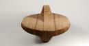
Through a series of hands-on technical exercises and material investigations, I chose cardboard as my primary design material in my furniture design course, and I was excited to explore its endless possibilities. Cardboard is an incredibly versatile material that is widely used in various fields. Its sustainability and ease of processing made it a preferred material for many industries. In addition, the unique honeycomb geometry structure of cardboard provided incredible strength and flexibility for furniture design. I utilized computer 3D modeling and laser cutting to achieve my design concept.
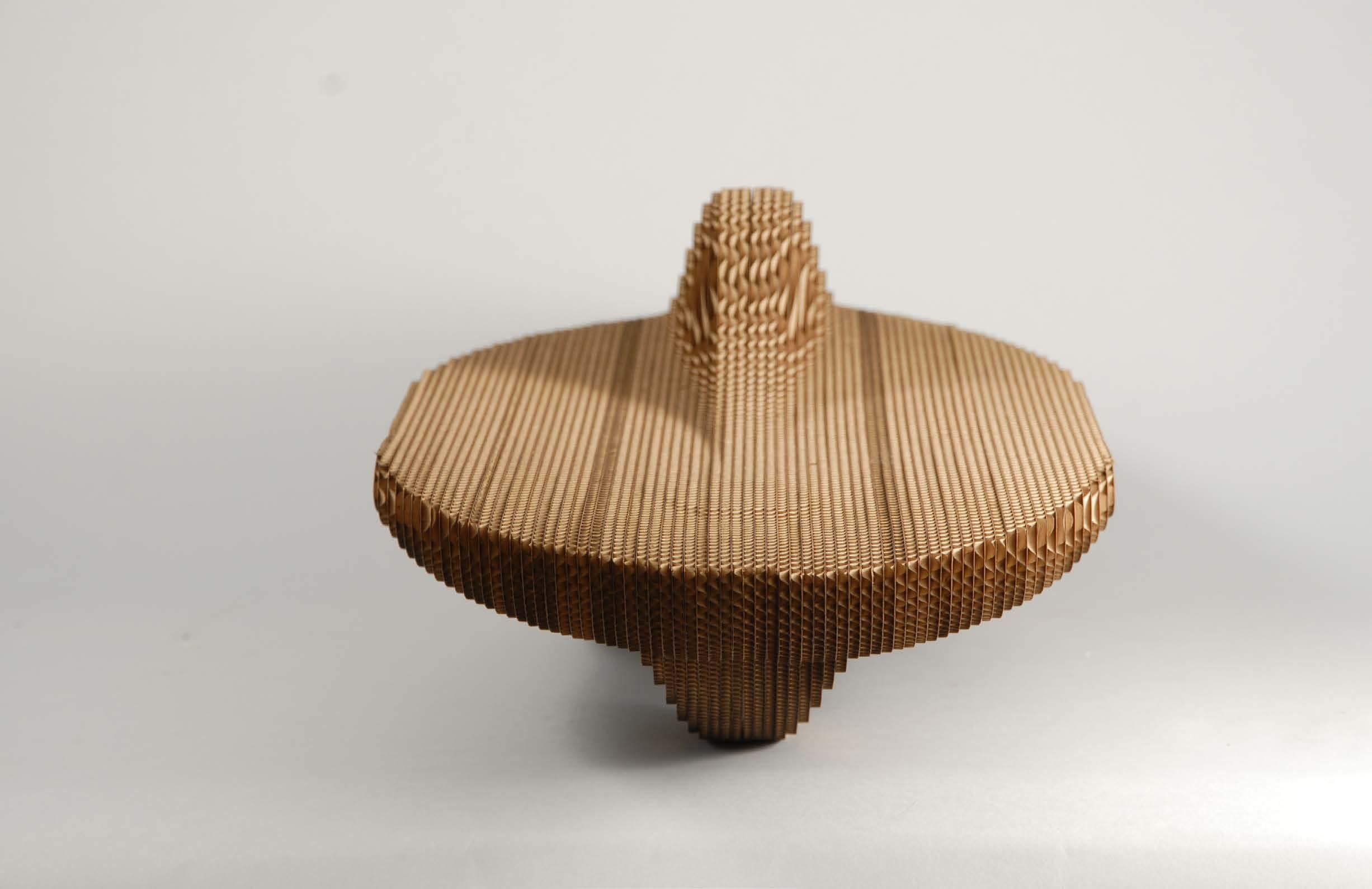
Laser cutting technology is a powerful tool that has revolutionized the way architects and designers create physical models, mock-ups, and prototypes. By using computer-aided design software (CAD), architects can create precise 2D and 3D drawings that can be easily translated into laser cutter-readable files. These files can then be used to create intricate and detailed physical models and prototypes using a laser cutter. Laser cutters use a high-powered laser beam to cut, etch, or engrave a wide variety of materials such as wood, plastic, metal, and even stone. One of the main benefits of laser cutting technology is its ability to create extremely intricate and precise designs with ease.
I was able to create complex geometric patterns, intricate textures, and detailed engraving with the laser cutter, which would have been difficult or impossible to achieve with traditional methods. This allowed me to quickly and accurately create a series of physical models of my furniture designs.

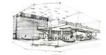
During my four-year college experience, I took professional sketching courses to enhance my ability to represent three-dimensional space through techniques like sketching plaster casts or live models. These courses helped me refine my hand-drawing skills.

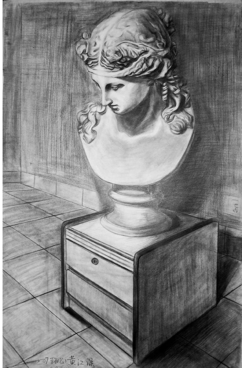

During my graduate studies in architecture, I persisted in practicing sketching. By portraying architecture and landscapes, I consistently enhanced my comprehension of objects, space, and light. Sketching also enabled me to further cultivate my proficiency in visual representation, thereby facilitating more effective expression of my design concepts.
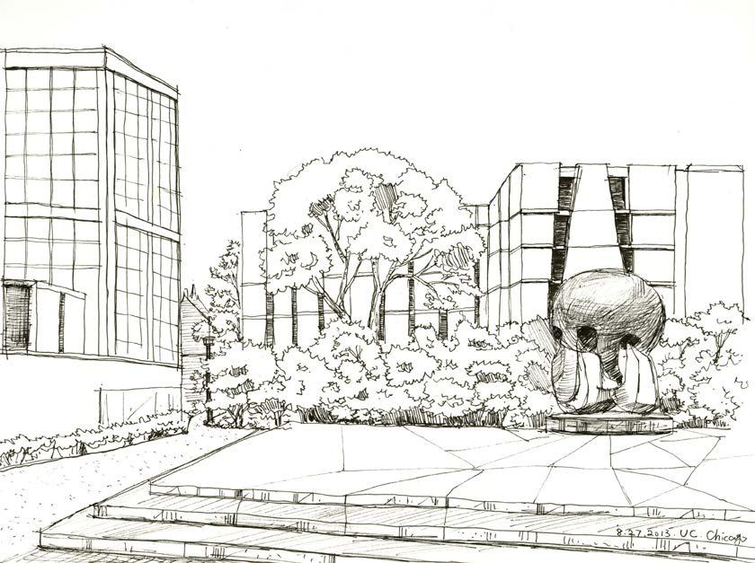
In my opinion, Sketching is a visual art that can help you improve your ability to express visually. Through sketching, you can learn how to accurately observe objects and depict observed details on paper. Sketching can help you better understand three-dimensional space and represent it in your drawings. This is crucial for architecture and interior design, which involve designing and utilizing space. sketching is highly beneficial for architecture and interior design, as it can help improve hand-eye coordination, visual expression ability, spatial awareness, creativity, and drawing skills, allowing you to better express your design ideas and concepts.