1.3 FACAD ECONCEPT




Building Envelope Design intentions and approaches:


Lorem ipsum dolor sit amet, consectetuer adipiscing elit. Nam cursus. Morbi ut mi. Nullam enim leo, egestas id, condimentum at, laoreet mattis, massa. Sed eleifend nonummy diam Praesent mauris ante, elementum et, bibendum at, posuere sit amet, nibh. Duis tincidunt lectus quis dui viverra vestibulum Suspendisse vulputate aliquam dui. Nulla elementum dui ut augue. Aliquam vehi cula mi at mauris. Maecenas placerat, nisl at consequat rhoncus, sem nunc gravida justo, quis eleifend arcu velit quis lacus. Morbi magna magna, tincidunt a, mattis non, imperdiet vitae, tellus. Sed odio est, auctor ac, sollicitudin in, consequat vitae, orci. Fusce id felis. Vivamus sollicitudin metus eget eros.


Base on the idea of providing a reliable and effective building envelope, the curtain wall is the most common solution which allows enough daily sunlight and great views facing the bay. We applied two kinds of glazing systems to the project, unitized system for tower including office and hotel division, and cable net system for the podium to allow maximum strengths and transparency on the ground level.
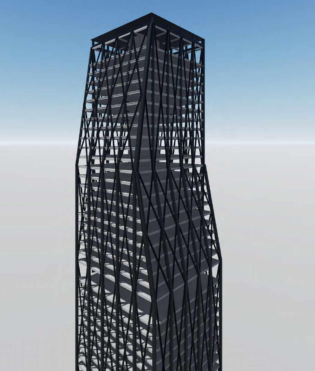
The unitized system is fixed at the top but flexible at the bottom, connected by stack joint, to follow the slight movements by lateral force. The façade is behind diagrid members, fundamentally connected and supported by the structural columns sitting around the tower. Such decisions of letting the diagonal exterior frame to be exposed are to ensure the lightweight of façade and avoid extra structural pressure. Additionally, to dissolve the contrast between vision and spandrel panel, we are using “shadow box” to detail the spandrel panel and hide the floor slab behind it. All the essential installations such as fire stops and insulation are considered and applied to the façade. To ensure the aesthetic experiences of users and clients, we also considered the room for finishing elements, for instance, the gap for pelmet and suspended ceiling to hide the structure bondeck above.


As the floor slabs have variations on the area because of the core gets smaller on higher levels, the façade of the building has gradient slopes. To make sure of the feasibility of gradient enclosure, we customize some connecting elements’ profiles while keeping structural strengths to follow the slope. Such as the frame of the glazing and the fixing bracket which connects façade with slabs.


Pellentesque habitant morbi tristique senectus et netus et malesuada fames ac turpis egestas In posuere felis nec tortor. Pellentesque faucibus. Ut accumsan ultricies elit. Maecenas at justo id velit placerat molestie. Donec dictum lectus non odio. Cras a ante vitae enim iaculis al iquam. Mauris nunc quam, venenatis nec, euismod sit amet, egestas placerat, est. Pellentesque habitant morbi tristique senectus et netus et malesuada fames ac turpis egestas Cras id elit. Integer quis urna. Ut ante enim, dapibus malesuada, fringilla eu, condi mentum quis, tellus. Aenean porttitor eros vel dolor. Donec convallis pede venenatis nibh. Duis quam. Nam eget lacus. Aliquam erat volutpat. Quisque dignissim congue leo. Mauris vel lacus vitae felis vestibulu m volutpat. Etiam est nunc, venenatis in, trist ique eu, imperdiet ac, nisl. Cum sociis natoque penatibus et magnis dis parturient montes, nascetur ridiculus mus. In iaculis facilisis massa. Etiam eu urna. Sed porta. Suspendisse quam leo, molestie sed, luctus quis, feugiat in, pede. Fusce tellus. Sed metus augue, convallis et, vehicula ut, pulvinar eu, ante. Integer orci tellus, tristique vitae, consequat nec, porta vel, lectus. Nulla sit amet diam. Duis non nunc. Nulla rhoncus dictum metus. Curabitur tristique mi condimentum orci. Phasellus pellentesque aliquam enim. Proin dui lectus, cursus eu, mattis laoreet, viverra sit amet, quam. Curabitur vel dolor ultrices ipsum dictum tristique Praesent vitae lacus. Ut vel it enim, vestibulum non, fermentum nec, hendrerit quis, leo. Pellentesque rutrum malesuada neque


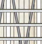
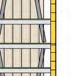
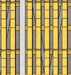
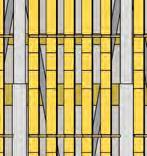
For the shading system, we mainly applied the system two sides of the building, north, and west since the site is not facing direct north. This could allow us to save the shading on the east façade, which is facing the bay, giving the most view to the users. As all of the shading systems, we having been supported by the structural columns, which means the shading system has the distance to the façade, (the diagrid members is between the shading system and curtain wall), we applied different shading systems for the facades following the basic rule of horizontal for North and vertical for West. For the North façade, the horizontal shading consists of two main parts, shading and capping. The capping is a timber frame supported sloped surface sitting upon the horizontal shading, this could make the shading more effective in summer while hiding the spandrel panel. For the West façade, to work to the site, we applied 45-degree vertical shading systems, the vertical panels are double of floor to floor height, hanging under a horizontal frame, this could allow the universal gap between each shading unit, even for where is the mechanism floor.
Nunc tempus felis vitae urna. Vivamus porttitor, neque at volutpat rutrum, purus nisi elei fend libero, a tempus libero lectus feugiat felis. Morbi diam mauris, viverra in, gravida eu, mattis in, ante. Morbi eget arcu. Morbi porta, libero id ullamcorper nonummy, nibh ligula pulvinar metus, ege t consectetuer augue nisi quis lacus. Ut ac mi quis lacus mollis aliquam. Curabitur iaculis tempus eros. Curabitur vel mi sit amet magna malesuada ultrices. Ut nisi erat, fermentum vel, congue id, euismod in, elit. Fusce ultricies, orci ac feugiat suscip it, leo massa sodales velit, et scelerisque mi tortor at ipsum. Proin orci odio, co mmodo ac, gravida non, tristique vel, tellus. Pellentesque nibh libero, ultricies eu, sagittis non, mollis sed, justo. Praesent metus ipsum, pulvinar pulvinar, porta id, fringilla at, est. Phasellus felis dolor, scelerisque a, tempus eget, lobortis id, libero. Donec scelerisque leo ac risus. Praesent sit amet es t. In dictum, dolor eu dictum porttitor, enim felis viverra mi, eget luctus massa purus quis odio. Etiam nulla massa, pharetra facilisis, volutpat in, imperdiet sit amet, sem. Aliquam nec erat at pur us cursus interdum. Vestibulum ligula augue, bibendum accums an, vestibulum ut, commodo a, mi. Morbi ornare gravida elit. Integer congue, augue et malesuada iaculis, ipsum dui aliquet felis, at cursus magna nisl nec elit Donec iaculis diam a nisi accumsan viverra. Duis sed tellus et tortor vestibulum gravida. Praesent elementum elit at tellus Curabitur metus ipsum, luctus eu, malesuada ut, tincidunt sed, diam Donec quis mi sed magna hendrerit accumsan. Suspendisse risus nibh, ultricies eu, volutpat non, condimentum hendrerit, augue. Etiam eleifend, metus vitae adipiscing semper, mauris ipsum i aculis elit, congue gravida elit mi egestas orci. Curabitur pede.
Melbourne School of Design APPLIED ARCHITECTURAL TECHNOLOGY Subject Co ordinator: Dr Gior gio Marfella
Author
Student ID 123456
Given Name Family Name
Fanshunze YANG 800376
Melbourne School of Design APPLIED ARCHITECTURAL TECHNOLOGY Subject
Coordinator: Dr Giorgio Marfella PART 2
GENERAL ARRANGEMENT DRAWINGS




N WIN D C L IMATE: ME L BOURNE 3pm ANNUAL 9am ANNUAL Images source: Australian Bureau of Meteorology, Wind Roses CALM 8% CALM 3% ABPL90118 Applied Architectural Technology Final Submission T eam Member T eam Member T eam Member Tutor Tutorial N. KAI LIN FANSHUNZE YANG SHAUN LIM Noel Tighe 05 Due Date Drawing A1.1 825663 800376 1155246 19June 2020 SITE PLANS AND DESIGN RESPONSE Southern Cross Station Central Equity Apartments Marvel Stadium View Docklands View Port Phillip Bay View Melbourne CBD View Flagstaff Gardens View Southern Cross Station View 241.7m SOUTHERN CROSS STATION Summer Sun LonsdaleStreet Spencer Street LittleLonsdaleStreet LittleLonsdaleStreet LonsdaleStreet View(Bay) View(Bay) View(Bay) View(Bay) View(Bay) View View View View View SITE PLAN 1:2500 @ A2 TRAM, TRAIN AND PEDESTRIAN CIRCULATION TOWER HEIGHT CIRCULATION & ACCESS SHADOW DIAGRAM RESPONSE TO VIEW VIEW FROM TOWER SUBTRACT PUBLIC SPACE SUN PATH Not to Scale 03 WIND RESPONSE A1.1 Not to Scale 02 WIND ROSE DIAGRAMS A1.1 Not to Scale 01 SITE RESPONSE A1.1


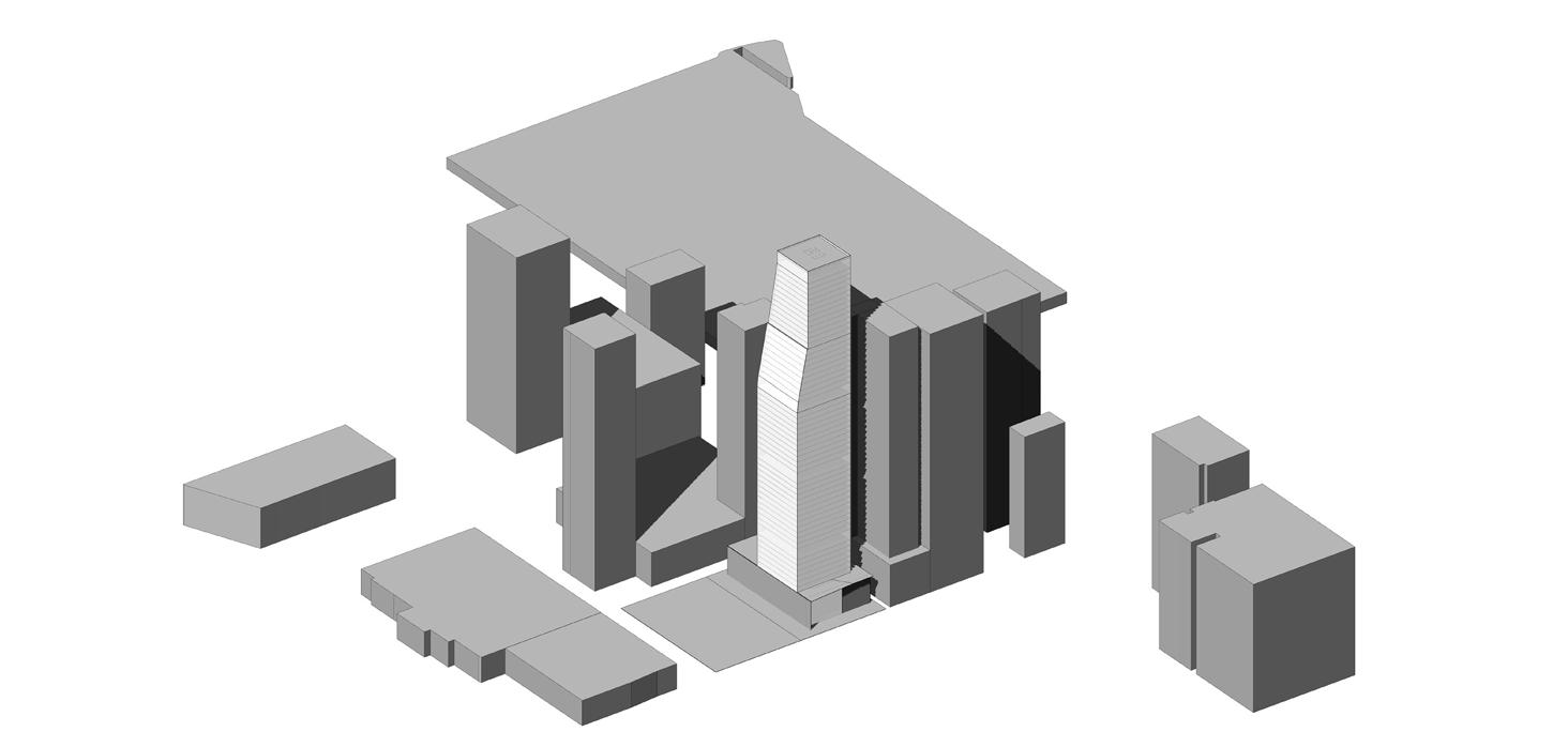
Our skyscraper is a celebration of spatial freedom through responding towards views of Port Phillip Bay and West Melbourne from the CBD. Due to the unrestricted views from the Medium to High Rise portion of the site, our design embraces these perspectives and implements public viewing spaces for the residents of the tower.
ABPL90118 Applied Architectural Technology Final Submission T eam Member T eam Member T eam Member Tutor Tutorial N. KAI LIN FANSHUNZE YANG SHAUN LIM Noel Tighe 05 Due Date Drawing A1.2 825663 800376 1155246 19June 2020 MASSING CONCEPTS Not to Scale 01 PHYSICAL MODEL A1.2 Not to Scale 03 TOWER PLATE AND CORE DEVELOPMENT A1.2 Not to Scale 02 ARCHITECTURAL RENDER A1.2
The skyscraper also responds towards the relationship between Lonsdale Street and Little Lonsdale Street. The skyscraper acts as a transitionary space for vehicular access from Little Lonsdale into Lonsdale Street. There is a service entrance and underground parking access from Little Lonsdale Street, major drop off points to the Office and Hotel buildings are accessible from Lonsdale Street. Through the extrusion and subtraction of forms, the tower achieves a unique form that provides character to the Melbournian skyline. With a 242 metre height, the skyscraper towers over its neighbours.
The total height of the project is 272.8 meters. According to the set back policy, the set back from site boundaries to secondary street is 16.368 meters.

UNDERGROUND
PODIUM GF GF 20 4365 2882 66.02%


PODIUM MECHANICAL FLOOR F 1F 8.4 1600
LOW RISE 2F-19F 18 4.2 1600 1240 77.50%
LOW RISE MECHANICAL FLOOR 20F 8.4 1600


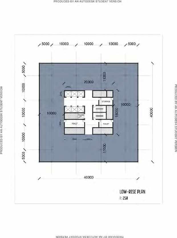
HIGH RISE 21F-31F11 4.2 1600 1343.5 83.96%
HIGH RISE MECHANICAL FLOOR 32F 8.4 1600
SKY LOBBY 32F (SHARE) 8.4 1600 1240 77.50%
SKY RISE (LOWER FLOORS) 33-41F 9 4.2 1450 (AVERAGE) 1297 89.45%
SKY RISE (HIGHER FLOORS) 42-53F 12 4.2 1129(AVERAGE) 1027 90.90%
SKY


Mechanical Floor 2 F Mechanical Floor 54 F Mechanical Floor 32 F Mechanical Floor 20 F 20000 20.000 Ground Floor F 3 F 4 F 5 F 8 F 9 F 10 F 11 F 12 F 13 F 14 F 15 F 16 F 17 F 18 F 19 F 21 F 22 F 23 F 24 F 25 F 26 F 27 F 28 F 29 F 30 F 31 F 33 F 34 F 35 F 36 F 37 F 38 F 39 F 40 F 41 F 42 F 43 F 44 F 45 F 46 F 47 F 48 F 49 F 50 F 51 F 52 F 53 F 55 F 6 F 7 F 28.400 32.600 36.800 41.000 45.200 49.400 53.600 57.800 62.000 66.200 70.400 74.600 78.800 83.000 87.200 91.400 95.600 99.800 104.000 112.400 116.600 120.800 125.000 129.200 133.400 137.600 141.800 146.000 150.200 154.400 158.600 167.000 171.200 175.400 179.600 183.800 188.000 192.200 196.400 200.600 204.800 209.000 213.200 217.400 221.600 225.800 230.000 234.200 238.400 242.600 246.800 251.000 255.200 263.600
EFFICIENCY TABLE level FLOORS FLOOR HEIGHT (m)GROSS FLOOR AREA (Sqm)NET LETTABLE AREA (Sqm) EFFICIENCY
CARPARK SERVICE
272.800 4200 4200 4200 4200 4200 4200 4200 4200 4200 4200 4200 4200 4200 4200 4200 4200 4200 4200 4200 4200 4200 4200 4200 4200 4200 4200 4200 4200 4200 4200 4200 4200 4200 4200 4200 4200 4200 4200 4200 4200 4200 4200 4200 4200 4200 4200 4200 4200 4200 4200 8400 9200 8400 8400 8400 0.000 40000 10000 7500 22500 1 3 6 10 15 25 M
UNDERGROUND
B 4 4300
CARPARK B2-3 2.5 4300
RISE MECHANICAL FLOOR 54F 8.4 984.25 CROW 55F 9.2 TOTAL 59 FLOORS 83575 80.88
Underground Car park Entrance OFFICE RECEPTION SITTING AREA + FRONT YARD OFFICE RECEPTION HOTEL LOBBY SHOP LITTLE LONSDALE STREET LONSDALE STREET Merriman Ln DOCKSIDE TOWER WILLIAM ANGLISS INSTITUTE OF TAFE 1:250 on A2 DROP OFF SHOP A B C D E F G H A B C D E F G H 1 2 3 4 5 6 7 8 9 11 12 13 14 1 2 3 4 5 6 7 8 9 15 10 15 11 12 13 14 10 PRODUCED BY AN AUTODESK STUDENT VERSION PRODUCED BY AN AUTODESK STUDENT VERSION PRODUCED BY AN AUTODESK STUDENT VERSION Podium Office Hotel Crown PODIUM PLAN 1:500 6 A1.3 LOW RISE PLAN 1:500 5 A1.3 MID RISE PLAN 1:500 4 A1.3 SKY RISE PLAN 1:500 2 A1.3 HIGH RISE PLAN 1:500 3 A1.3 ABPL90118 Applied Architectural Technology Final Submission Tutorial N. Tutor Noel Tighe 05 Drawing A1.3 T eam Member KAI LIN 825663 T eam Member FANSHUNZE YANG 800376 T eam Member SHAUN LIM 1155246 Due Date 19June 2020 ARCHITECTURAL PLANS AND SECTION
PLOT RATIO 13.75 %


C3 C4 C3 C3 Underground Car park Entrance OFFICE RECEPTION SITTING AREA + FRONT YARD Goods Lift (low) OFFICE RECEPTION HOTEL LOBBY SHOP LITTLE LONSDALE STREET LONSDALE STREET Merriman Ln DOCKSIDE TOWER WILLIAM ANGLISS INSTITUTE OF TAFE Podium Floor Plan Ground Floor 1:250 on A2 DROP OFF SHOP A B C D E F G H A B C D E F G H 1 2 3 4 5 6 7 8 9 11 12 13 14 1 2 3 4 5 6 7 8 9 15 10 15 11 12 13 14 10 PRODUCED BY AN AUTODESK STUDENT VERSION PRODUCED BY AN AUTODESK STUDENT VERSION PRODUCED BY AN AUTODESK STUDENT VERSION PRODUCED BY AN AUTODESK STUDENT VERSION 13610 15 M PODIUM FLOOR PLAN 1 : 200 1 A2.1 ABPL90118 Applied Architectural Technology Final Submission T eam Member T eam Member T eam Member Tutor Tutorial N. KAI LIN FANSHUNZE YANG SHAUN LIM Noel Tighe 05 Due Date Drawing A2.1 825663 800376 1155246 19June 2020 Typical Podium Floor Framing


C1: 1200 WC C2: 500 WC 440 C3: 400 WC 328 C4: 200 UC 60 = COLUMN IN SHEAR WALL EB1: 700 WB 150 B1: 700 WB 150 B2: 610 UB 125 B3: 460 UB 74 SL1: BONDEK 590mm WIDTH 120mm Thick C2: 500 WC 440 C3: 400 WC 328 C4: 200 UC 60 = COLUMN IN SHEAR WALL EB1: 700 WB 150 B1: 700 WB 150 B2: 610 UB 125 B3: 460 UB 74 SL1: BONDEK 590mm WIDTH 120mm Thick SKY RISE HOTEL FLOOR LEVEL 39 1:200 GOODS LIFTS B2 B2 B2B2 B2B2 B2B2 B2 B2 B2B2 B2B2 B2B2 B1 B1B1 B1 B1 B1 B1B1 B1 B1 B3B3B3 B3B3 B3 B3B3 B3B3B3 B3B3 B3 B3B3 B1 B1 B1 B1 B1 B1 B2 B2 B2 B2 B2 B2 B2 B2 B2 B2 B2 B2 B1 B1 B1 B1 B1 B1 EB1 EB1 EB1 EB1 C1 C1 C1 C1 C1 C1 40500 4500 3000 3000 3000 4500 2250 2250 9000 3000 3000 3000 4500 4500 9000 C1 C1 C1 C1 C1 C1 C1 C1 C1 C1 C4 C4 C4 C4 C4 C4 C D E F G C D E F G 3 5 7 8 10 12 PRODUCED BY AN AUTODESK STUDENT VERSION 9000 9000 9000 9000 9000 9000 9000 9000 9000 9000 2250 3000 8875 4500 13375 13075 3000 2250 2250 590 B2B2 B2B2 B2B2 B2B2 B2B2 B2B2 B2B2 B2B2 B2B2 B2B2 B1 B1 B1 B1 B1 B1 B1 B1 B3 B2 B2 B2 B2 B2 B2 B2 B2 B1 B1 B1 B1 B1 B1 B1 B1 B1 B1 B1 B1 HIGH RISE OFFICE FLOOR LEVEL 22 1:200 SL1 SL1 SL1 EB1 EB1 EB1 EB1 EB1 EB1 EB1 EB1 EB1 EB1 EB1 EB1 EB1 EB1 EB1 EB1 EB1 EB1 EB1 EB1 C1 C1 C1 C1 C1 C1 C1 C1 C1 C1 C1 C1 C2 C2 C2 C2 C2 C2 C2 C2 C2 B3 B3B3 B3B3 B3B3 B C D E F 3 5 7 8 10 12 9000 9000 9000 9000 9000 G 10 12 B C D E F G PRODUCED BY AN AUTODESK STUDENT VERSION PRODUCED BY AN AUTODESK STUDENT VERSION PRODUCED BY AN AUTODESK STUDENT VERSION Mechanical Floor 2 F Mechanical Floor 54 F Mechanical Floor 32 F Mechanical Floor 20 F 20.000 Ground Floor 1 F 3 F 4 F 5 F 8 F 9 F 10 F 11 F 12 F 13 F 14 F 15 F 16 F 17 F 18 F 19 F 21 F 22 F 23 F 24 F 25 F 26 F 27 F 28 F 29 F 30 F 31 F 33 F 34 F 35 F 36 F 37 F 38 F 39 F 40 F 41 F 42 F 43 F 44 F 45 F 46 F 47 F 48 F 49 F 50 F 51 F 52 F 53 F 55 F 6 F 7 F 28.400 32.600 36.800 41.000 45.200 49.400 53.600 57.800 62.000 66.200 70.400 74.600 78.800 83.000 87.200 91.400 95.600 99.800 104.000 112.400 116.600 120.800 125.000 129.200 133.400 137.600 141.800 146.000 150.200 154.400 158.600 167.000 171.200 175.400 179.600 183.800 188.000 192.200 196.400 200.600 204.800 209.000 213.200 217.400 221.600 225.800 230.000 234.200 238.400 242.600 246.800 251.000 255.200 263.600 0.000 1 3 6 10 15 25 45 M 13610 15 M Sky Rise Plan High Rise Plan OVERALL SECTION 1 500 1 A2.2 TOWER FLOOR FRAMING 1 : 200 2 A2.2 ABPL90118 Applied Architectural Technology Final Submission T eam Member T eam Member T eam Member Tutor Tutorial N. KAI LIN FANSHUNZE YANG SHAUN LIM Noel Tighe 05 Due Date Drawing A2.2 825663 800376 1155246 19June 2020 Overall Section and Typical Tower Floor Framing


ABPL90118 Applied Architectural Technology Final Submission T eam Member T eam Member T eam Member Tutor Tutorial N. KAI LIN FANSHUNZE YANG SHAUN LIM Noel Tighe 05 Due Date Drawing A2.3 825663 800376 1155246 19June 2020 TYPICAL FLOOR SECTIONS Melbourne Schoo of Design APPLIED ARCHITECTURAL TECHNOLOGY Subject Coordinator: Dr Giorgio Marfella 1 50 01 TYPICAL HOTEL FLOOR SECTION A2.3 1 50 02 TYPICAL OFFICE FLOOR SECTION A2.3 192.200 39 F 70.400 12 F 66.200 11 F 40 F196.400 700 WB 150 EDGE BEAM CONCRETE FLOORPLATE 700 WB 150 EDGE BEAM INSULATION LAYER SPANDREL PANEL VISION PANEL STRUCTURAL COLUMN INSULATION LAYER SPANDREL PANEL VISION PANEL HANGER WIRE SUSPENDED CEILING PANEL SUSPENDED CEILING PANEL AIR SUPPLY VENT STRUCTURAL COLUMN CONCRETE FLOORPLATE AIR SUPPLY VENT 1 3 6 10 15 M Corridor space with drop down bulk head near the service core containing the maintenance ducts for the level. Social break out spaces are feasible due to the wide span of the typical hotel floorplate. Hotel room space are located near the vision panels to allow natural lighting to improve quality of interior living space.




ABPL90118 Applied Architectural Technology Final Submission T eam Member T eam Member T eam Member Tutor Tutorial N. KAI LIN FANSHUNZE YANG SHAUN LIM Noel Tighe 05 Due Date Drawing A2.4 825663 800376 1155246 19June 2020 Structural Concept & 3D Modelling OVERALL STRUCTURE NORTH WESTERN FACADE NOT TO SCALE 1 A2.4 TOWER DIAGRID STRUCTURE NORTH-WESTERN FACADE NOT TO SCALE 2 A2.4 PODIUM STRUCTURAL CONCEPT NOT TO SCALE 3 A2.4




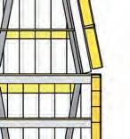


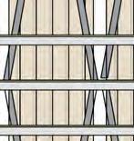












1 3 6 10 15 25 45 M 1 3 6 10 15 25 45 M ABPL90118 Applied Architectural Technology Final Submission T eam Member T eam Member T eam Member Tutor Tutorial N. KAI LIN FANSHUNZE YANG SHAUN LIM Noel Tighe 05 Due Date Drawing A3.1 825663 800376 1155246 19June 2020 Overall Elevations NORTH OVERALL ELEVATION 1:500 1 A3.1 WEST OVERALL ELEVATION 1:500 2 A3.1
Horizontal


4200 3000 1200 900 1500 1500 1500 1050 1000 1500 1050 1000 615 150 750 300 3000
North West Corner High Rise Office Level 22 1:100
Panel Mullions Vision Panel Triangular shading system cover the spandrel panel behind
AN AUTODESK STUDENT VERSION 4200 3000 1200 900 1500 1500 1500 10501000 1500 1050 1000 615 150750 300 3000
Horizontal shading panel with 150mm thickness West side 45 degree shading to block 83% of summer sun Triangular aluminum panels to cover the main structural columns Triangular aluminum panels to cover the diagrid system Spandrel
PRODUCED BY
shading panel with 150mm thickness
system
Panel Mullions Vision Panel Triangular shading system cover the spandrel panel behind
AUTODESK STUDENT VERSION 1000 800 30 1500 1500 1500 4000
West side 45 degree shading to block 83% of summer sun Triangular aluminum panels to cover the main structural columns Triangular aluminum panels to cover the diagrid
Spandrel
PRODUCED BY AN
PRODUCED BY AN AUTODESK STUDENT VERSION
1000 80030 150015001500 4000
Western side shading : Vertical panels 800mm deep horizontal 800mm deep spacing 1500mm Western North Corner High Rise Office Level 22 1:100
PRODUCED BY AN AUTODESK STUDENT VERSION
PRODUCED BY AN AUTODESK STUDENT VERSION PRODUCED BY AN AUTODESK STUDENT VERSION PRODUCED BY AN AUTODESK
Shading Cap hiding the Spandrel Colored Vision Panel Spandrel Panel ABPL90118 Applied Architectural Technology Final Submission T eam Member T eam Member T eam Member Tutor Tutorial N. KAI LIN FANSHUNZE YANG SHAUN LIM Noel Tighe 05 Due Date Drawing A3.2 825663 800376 1155246 19June 2020 Enlarged Elevations EXPLODED DIAGRAM - NORTH HORIZONTAL SHADING NOT TO SCALE 3 A3.2 NORTH WEST CORNER HIGH RISE OFFICE - LEVEL 22 1:100 1 A3.2 WESTERN NORTH CORNER HIGH RISE OFFICE - LEVEL 22 1:100 2 A3.2
Western side shading : Vertical panels 800mm deep horizontal 800mm deep spacing 1500mm
STUDENT VERSION


ABPL90118 Applied Architectural Technology Final Submission T eam Member T eam Member T eam Member Tutor Tutorial N. KAI LIN FANSHUNZE YANG SHAUN LIM Noel Tighe 05 Due Date Drawing A3.3 825663 800376 1155246 19June 2020 Facade Concept 3D Model WESTERN - SOUTHERN FACADE NOT TO SCALE 1 A3.3 NORTH - WESTERN FACADE NOT TO SCALE 2 A3.3 PODIUM FACADE NOT TO SCALE 3 A3.3
Melbourne School of Design APPLIED ARCHITECTURAL TECHNOLOGY Subject
PART
Coordinator: Dr Giorgio Marfella
3 DETAILED DESIGN DRAWINGS


HEAVY DUTY SPIDER 446/4M 200MM FIXED M10 CSK SCREW SPIDER ROUTEL COUNTERSUNK POINT FIXING (ROTULE TYPE)DETAIL BELOW WEATHER SEAL (TRANSPARENT SILICONE) 12MM WIDTH 18MM 7*19 STAINLESS WIRE ROPE 316 MARINE GRADE CABLE 4*RS PRO M10 X 40MM HEX SOCKET CAP SCREW STAINLESS STEEL Φ ″ Φ ″ ™ ” ® KRS 4.8х25–Neoprene Rubber PAD ASSIGNMENT 4A & 4B APBL90118 APPLIED ARCHITECTURAL TECHNOLOGY 2020 SEMESTER 1 DRAWN BY: KAI LIN STUDENT ID: 825663 INDIVIDUAL TASK DATE: PAPER06/06/2020 SIZE: A1ISSUE NO. 02 TITLE: RESOLVE THE STRUCTURAL GLASS FAÇADE DESIGN OF THE LOBBY/SIGNIFICANT AREA OF DRAWINGSHOPFRONTS; NO A4.2KRS 4.8х25A4.1 ELEVATION OF THE SPIDER20400.0 KRS 4.8х25 KRS 4.8х25ABPL AppliedArchitectural Technology Group Name: Number:Drawn By: Tutor N. KAI LIN 825663 Noel Tighe 05 Detailed Design - Drawing A4.2 HUNGRY ARCHITECTSTHE STRUCTURAL GLASS FAÇADE OF THE LOBBY/SIGNIFICANT AREA OF PODIUM SHOPFRONTS;DrawnNumber: ShaunShaun Lim NoelTighe05 A4.2 Office Facade Key Construction Details 19 JUNE 2020 6000 5500 9250 9000.0 5500 9000.0 9000.0 9000.0 9000.0 8880.0 22.5 20000.0 1500.0 1200.0 4700 4700 4500 20000 1200.0 75.0 1100 1500.0 1500.0 3000.0 4700 5000 1500.0 5000 1108.0 200.0 1200.0 466.0 3000.0 12940 1340.0 1460 900 1500.0 1710 1350 1810 1340.0 PODIUM PLAN 1:250 @ A1 PODIUM ELEVATION 1:250 @ A1 PODIUM RENDER PODIUM RENDER DETAILED ELEVATION OF SHOPFRONT 1:50 @ A1 SECTION BB 1:50 @ A1 SECTION AA 1:50 @ A1 BACK YARD, SEMI-OPEN SPACE FOR TOWER USERS MECHANICAL FLOOR FOOD COURT & PUBLIC GATHERING HALL ENTRY, CORRIDOR TO GROUND FLOOR HOTEL LOBBY LUXURY SHOPS RL 18660.00 RL 20000.00 18660.0 MECHANICAL FLOOR (DETAILS ON TASK 02, COMPLETED BY SHAUN LIM PRODUCED BY AN AUTODESK STUDENT VERSION PRODUCED BY AN AUTODESK STUDENT VERSION PRODUCED BY AN AUTODESK STUDENT VERSION ABPL90118 Applied Architectural Technology Group Name: Drawing: Scale: Drawn By: Tutor Tutorial N. KAI Shaun LIN Noel Tighe 05 Due Date Drawing A4.1 HUNGRY ARCHITECTS 825663 19June 2020 PODIUM FACADE: GENERAL ARRANGEMENT AS INDICATED @ A1

RWH 200, 104,6 KN CPACITY, 12, 2MM STROKE THREAD ROD SIZE M20 THREAD DIAMETER 20MM M20*60MM CONNECTING/COUPLING NUT HEX NUT 12MM STEEL PLATE M20*80MM CONNECTING/COUPLING NUT THREAD SIZE M20 THREAD DIAMETER 20MM TENSION RODS 12 EYE FITTING, MODEL G01-Φ12 TENSION ROD, FIT WITH DIAMETER 12MM ROD HEX SOCKET BUTTON SCREW ISO 7380 M20 4*M12 THREADED ROD, FASTENED INTO CONCRETE WITH HEAVY DUTY DROP-IN ANCHORS DYNASET™ DSM12SS STAINLESS STEEL AISI 316 AG50 GRILEE: A FRAME: THE 1/8” BAND AROUND THE CORE DELIVERS A MINIMALIST PROFILE, THIS FRAME STYLE ALSO HAS A 1/2” RETURN ON THE BOTTOM FOR SUPPORT AND ALLOWS FOR THE CORE TO BE LOOSE (REMOVABLE) OR 18MM THICK MARBLE TILES AS FLOOR FINISH 4MM THICK BOND COAT RAINTRAK® - THRESHOLD DOOR DRAINAGE 120 MM RTO 123L(NOMINAL WIDTH) 123MM DEPTH: 120MM M4*38MM CONCRETE WALL ANCHOR EQUAL ANGLE TO SUPPORT THE DUCTED PIPE HVAC SYSTEM, AIR VENTILATION 25MM THERMAL INSULATION OF RECTANGULAR DUCT WITH PAROC HVAC SLAB ALUCOAT AIR PATTERN, DIFFUSER ,FLOOR 0° DEFLECTION THE AIR DIFFUSER BETWEEN TWO VERTICAL CABLES MINIMIZE THE HOT AIR IMPACT TO STEEL COMPONENTS. M4 BOLTS, FASTEN THE UNEQUAL ANGLE STEEL PLATE 28MM WIDTH STAINLESS CABLE FERRULE STRUCTURAL SILICON FIXING ANCHOR BOLTS TO THE CONCRETE SETTING BLOCK ALUMINUM U-CHANNEL 19MM TOUGHENED GLASS 2° SLOPE LIQUID RUBBER 2MM WATERPROOFING LAYER 400 WC 270 G-6422 GREEN PIN® OPEN SPELTER SOCKET BN (MM) STRUCTURAL SILICONE FOR WATERPROOFING +RUBBER PAD AT THE EDGE OF ALUMINUM PANEL. MINIMIZE THE DAMAGE CAUSES BY FRICTION 55 EA 6MM SUPPORT THE ALUMINUM PLATE 75MM Z STEEL PLATE AS RAILING TO SUPPORT THE GLASS PANE M12 BOLTS AND 12MM STEEL PLATE TO FASTEN THE UNIVERSAL BEAM. 610 UB 125 AUTOMATIC DOOR DETAIL, FIX TO THE UNIVERSAL BEAM ABOVE. 6MM ALUMINUM CLADDING PANELS, FOLDED TO 90 DEGREE 400 WC 270 1200MM HEIGHT BALUSTRADES CLAMPED RIGID BASE TOP CAP U-CHANNEL 4MM THICKNESS 20MM STRUCTURAL SILICONE TO ADHERE THE CHANNEL HARWOOD OR EPOXY POLYSULPHIDE COMPOUND 100 UEA 12 AND 90EA 10 M8 ANCHOR BOLT TO ANCHOR IT TOP REINFORCEMENT 35MM BELOW THE CONCRETE SURFACE FOLDED EDGE BONDEK BLACK SPANDREL PANEL TO COVER THE CONCRETE FLOOR SLAB AND CEILING 200MM LENGTH 12MM THICKNESS STEEL PLATE TO FIX THE UNIVERSAL BEAM WITH M8 BOLTS 610UB125 PURLIN C150-20 H PEEL THE ALUMINUM PANEL TO SHOW THE VERTICAL STRUCTURAL COLUMN AND DETAILS BEHIND 12MM SILICONE TO SEAL THE ALUMINUM PANELS 12MM STEEL PLATE SLIDING RAIL FOOTING OF STEEL COLUMN CONNECTION WITH 25MM NON-SHRINK GROUT 1200MM 10MM THICK MARBLE FLOOR TILES BOND COATING 4MM THICK NON-SHRINK GROUT BASE PLATE + THREADED RODS THREADED ROD WITH 50MM COG 6MM THICKNESS ALUMINUM PPANEL CLADDING FIXED CASSETTE (SEALED) 75 35mm TOP HAT MOISTURE BABBIER 28*20*1.6 MM ALUMINUM ANGLE FIXED TO ALUMINUM FRAME WITH 10 TEK @450 CRS 55 EA 6 AS THE FRAME OF CLADDING FRAMEWORK OF CLADDING SYSTEM FRAMEWORK OF ALUMINUM CLADDING WELD TO THE UNIVERSAL BEAM Z PLATE TO CONNECT THE TOP CAP OF THE GLAZING INSTEAD OF SETTING BLOCK, GAP TO PREVENT DEFLECTION OF STRUCTURAL MATERIAL OR SLIP OF GLASS PANES. ANCHOR PLATE WITH COMPRESSION BARS FORMED METAL COPING WATERPROOFING SILICONE SEALANT 12MM STRUCURAL SILICONE USED TIE ROD HYDRAULIC CYLINDER CLEVIS CONNECTION TENSION ROD FALL 2 DEGREE HEAVY DUTY SPIDER 446/4M 200MM FIXED M10 CSK SCREW SPIDER ROUTEL COUNTERSUNK POINT FIXING (ROTULE TYPE)DETAIL BELOW WEATHER SEAL (TRANSPARENT SILICONE) 12MM WIDTH 18MM 7*19 STAINLESS WIRE ROPE 316 MARINE GRADE CABLE 4*RS PRO M10 X 40MM HEX SOCKET CAP SCREW STAINLESS STEEL FRONT ELEVATION OF THE SPIDER 10-24 *16MM HEX. HEAD SELF-DRILLING SCREW MIDWAY BETWEEN EMBOSSMENTS. MondoClad solid aluminium cladding panels 20*20*1.6 ALUMINUM ANGLE FIXED TO ALUMINIUM FRAME WITH #10 TEK SCREWS@ 450 CRS 75*35MM TOP HAT 55 EA 6MM THICKNESS 65 EA 8 6MM MondoClad® non-combustible certified to AS1530.1 MondoClad solid aluminium cladding panels CHROME BLACK ANODISED FINISH 18MM STEEL CABLE 12MM TOUGHENED GLASS PANE AS ROOF SSG SUPPORT STRUCTURAL SILICONE SEALANT EDGE FORM OF THE BONDEK BEND CORNER OF EDGE FORM WITH 90 DEGREE, OVERLAPPING BOTTOM FLANGES TOP MESH REINFORCEMENT SL1, COMPOSITE STEEL DECKING 120MM THICK CONTINUOUSLY SUPPORTED @ 3M MAX. C-SHAPE PURLIN 250-25 H RONDO 80MM (H) X 25MM (W) BRACKET –121 ROD TO TIMBER/STEEL RONDA 110MM (H) X 38MM (W) SUSPENSION CLIP - SUITS 125/127/128 TOP CROSS RAIL RONDA 200MM (L) X 21MM (W) SECTION JOINER – SUITS 125/127/128 TOP CROSS RAIL RONDA 16MM (H) X 38MM (FACE) FURRING CHANNEL 25MM TIMBER CEILING BOARD 610 UB 125 EDGE BEAM G-6422 GREEN PIN® OPEN SPELTER SOCKET BN (MM) ALUMINUM CHANNEL AND 5MM THICK RUBBER PAD TO PROTECT THE TOUGHENED GLASS PANE. STEEL PLATE WELD TO THE BOTTOM OF BEAM HORIZONTALLY MECHANICAL FLOOR DETAILS ON TASK 02, COMPLETED BY SHAUN LIM CUSTOMIZED SPACED FRAME STRUCTURAL SUPPORT 1000MM EXTEND OUT 600MM HEIGHT DIRECTLY FIX TO THE STRUCTURAL COLUMNS WITH BOTLS 18MM RADIUS CYLINDERS STRUCTURAL COLUMNS 340 875 25 380 350 128.0 120.0 4000.0 4000.0 1800 134.0 1800 200UB30 18MM CYLINDER AS SECONDARY STRUCTURE OF PODIUM MODULE. SUSPENDED LAMP 1300 266.0 56.0 700.0 1512.0 466.0 250.0 SECTION AA DETAIL TOP HORIZONTAL BEAM 1:20 @ A1 ISOMETRIC DRAWING OF PODIUM MODULE PLAN OF PODIUM MODULE STRUCTURE 1:50 @ A1 SECTION AA DETAIL BOTTOM 1:20 @ A1 DETAIL FRONT ELEVATION OF SPIDER FITTING 1:10 @ A1 DETAIL SECTION OF SPIDER FITTING 1:10 @ A1 BASE FLASHING SHOULD EXTEND 205-305MM ABOVE HIGHEST ANTICIPATED WATERLINE CANT STRIP CAP OR COUNTERFLASHING 600.0 PRODUCED BY AN AUTODESK STUDENT VERSION PRODUCED BY AN AUTODESK STUDENT VERSION PRODUCED BY AN AUTODESK STUDENT VERSION ABPL90118 Applied Architectural Technology Group Name: Drawing: Scale: Drawn By: Tutor Tutorial N. KAI Shaun LIN Noel Tighe 05 Due Date Drawing A4.2 HUNGRY ARCHITECTS 825663 19June 2020 PODIUM FACADE: DETAILS AS INDICATED @ A1
01 OFFICE FACADE ELEVATION 1 : 30 1 30 1 30 02 OFFICE FACADE SECTION 03 OFFICE FACADE PLAN A4.3 A4.3 A4.3 Not to Scale 04 FACADE ISOMETRIC A4.3 A4.4 A A4.4 D A4.4 B A4.1 02 A4.3 03 SINGLE GLAZED SPANDRAL SUSPENDED CEILING PANEL 700 WB 150 EDGE BEAM CONCRETE FLOORPLATE 1200 WIELDED STRUCTURAL COLUMN MECHANICAL FLOOR ALUMINIUM LOUVRES STRUCTURAL DIAGRID INSULATION BLANKET FIXED TO UNDERSIDE OF SLAB ON MECHANICAL FLOOR AIR SUPPLY VENT DOUBLE GLAZED UNITIZED VISION PANELS CURTAIN WALL FIXING BRACKET CURTAIN WALL FIXING BRACKET HORIZONTAL SHADING (NORTH FACADE) SPANDRAL PANEL 1200 WIELDED STRUCTURAL COLUMN STRUCTURAL DIAGRID DOUBLE GLAZED UNITIZED VISION PANELS HORIZONTAL SHADING (NORTH FACADE) MECHANICAL FLOOR ALUMINIUM LOUVRES ABPL90118 Applied Architectural Technology Group Name: Drawing: Scale: Drawn By: Tutor Tutorial N. SHAUN Shaun LIM Noel Tighe 05 Due Date Drawing A4.3 HUNGRY ARCHITECTS 1155246 19June 2020 TYPICAL OFFICE FACADE: GENERAL ARRANGEMENT AS INDICATED @ A1 31 F154.400 32 F158.600 31 F154.400 32 F158.600
OFFICE FLOOR CONNECTION 1 : 5 B A4.4 GLASS PANEL TRANSOM 1 5 C A4.4 SPANDREL TRANSOM 1 5 A4.4 A CLADDING CONNECTION FOR SHADING 1 5 D A4.4 HORIZONTAL SHADING FIXTURE 1 : 5 F A4.4 HORIZONTAL SHADING EXTRUDING FINS DETAIL 1 5 E A4.4 STEEL EDGE BEAM (700 WB 150) CAST-IN INSERT PRIMARY FLOOR ANGLE BRACKET ANCHOR BOLTS ALUMINIUM SILL COVER HOOK-ON BRACKET INSULATION LAYER SMOKE FLASHING REBATED IN CONCRETE SLAB INTERNAL C SECTION FRAME SCREW BOLTS ANCHOR BOLTS INTERNAL TRUSS STRUCTURE ALUMINIUM CLADDING INTERNAL C SECTION FRAME SPANDREL PANEL STACK HEAD JACKING BOLT SILL TRANSOM ALUMINIUM STACK JOINT ROLLER BLIND SUSPENDED CEILING PANEL ABUTTING ROLLER BLIND WATERPROOF SEALANT SPANDREL PANEL INSULATION LAYER VISION PANEL INTERNAL BOX TRUSS HIDDEN FIXING SCREW BOLT ANCHOR BOLTS STRUCTURAL COLUMN COLUMN FIXING PLATE EXTERNAL FIXING TAB STRUCTURAL COLUMN ANCHOR BOLTS SCREW BOLT STRUCTURAL COLUMN HIDDEN FIXING SCREW BOLTS ABPL90118 Applied Architectural Technology Group Name: Drawing: Scale: Drawn By: Tutor Tutorial N. SHAUN Shaun LIM Noel Tighe 05 Due Date Drawing A4.4 HUNGRY ARCHITECTS 1155246 19June 2020 TYPICAL OFFICE FACADE: DETAILS 1:5 @ A1

800 x 800 Structural Col. Hanger wire Diagrid members B2 610 UB 125 Finished ceiling level 45 F217.400 46 F221.600 47 F225.800 48 F230.000 2 A4.5 2 A4.5 3 A4.1 3 A4.1 1ELEVATION SCALE: 1:50 A4.5 2PLAN _ level 45 SCALE: 1:50 A4.5 3D Perspective A4.5 3SECTION SCALE: 1:50 A4.5 1234 9 M 5 A4.6 4 A4.2 ABPL90118 Applied Architectural Technology Group Name: Drawing: Scale: Drawn By: Tutor Tutorial N. FANSHUNZE Shaun YANG Noel Tighe 05 Due Date Drawing A4.5 HUNGRY ARCHITECTS 800376 19June 2020 TYPICAL HOTEL FACADE: GENERAL ARRANGEMENT AS INDICATED @ A1
Acoustic Insulation Spandrel PanelInsulation Pressure Equalised Chamber 400 WC 303 Fixing Bracket End Capping details Drained Cavity Rainscreen Seals void void Mullion CappingDiagrid Members Bolts Shading C Section- C150 20mm Linear Panel Capping Edge Beam - 700WB 150 Flashing Internal frame Diagrid Member Slab Rebate Fire Stop Smoke Flash Bracket Slab Bondeck Column Spandrel Panel Vision Panel Shading Service Pipe Pelmet Suspended Ceiling B1 700WB 150 Angles 40 x 40 Bracket 5Detail Floor Section SCALE: 1:10 A4.6 4Detail Floor Plan SCALE: 1:10 A4.6 ABPL90118 Applied Architectural Technology Group Name: Drawing: Scale: Drawn By: Tutor Tutorial N. FANSHUNZE Shaun YANG Noel Tighe 05 Due Date Drawing A4.6 HUNGRY ARCHITECTS 800376 19June 2020 TYPICAL HOTEL FACADE: DETAILS AS INDICATED @ A1


