
Carapace Pavilion: Coupling digital intelligence in conceptualization and manual labor in fabrication
KayMashiach Synthesis
ConstructedHistoriesEssay CarlosAndresLoraYuen
ShajayBhooshan
Abstract
The Carapace Pavilion is an architecture that will be situated in Joshua Tree National Park, originally designed as a prototype for a new typeofouthousewithinthepark.The project situates itself within the design process and ideology of Architectural Geometry (AG), a dogma focusingon the development of shapes that provide structural optimality and ease of fabrication paired with the acquirement of skills demanded by implementing such complexity produced by artificial intelligence and computational design1. The required competence and proficiency in machinic and robotic learning thus necessitates collaborative efforts in the design process.
Architectural Geometry has become more prevalent in recent years as individuals within the relevant industries are seeking to build more complex systems, therefore prompting a pursuit of efficient construction encompassing cost, ease of build, and innovative material.TheCarapacePavilionisan experiment in all these circumstances as it explores the creation of an anticlastic, doubly curved, tubular structure employing the use of Ultra-High-Performance Concrete (UHPC), one foam mold, andfiveconstituentpanels.Thegoal of this project is to understand the ways in which computational tools such as Grasshopper can assist in achieving both a structurally sound system,anefficientuseofmaterials,
1 Bhooshan, Shajay. “Architectural Geometry and Tacit AI”. London: Architectural Association Design Research Lab and Zaha Hadid Computation and Design Group, 2021. pp 1.
and aesthetic agency2. Designing a concrete shell provided a study of the procedures involved to implement digital intelligence as a human extension3 in design while still exercising hand-operated machines and manual labor in the fabricationprocess.
Constructing systems that deploy topological optimization4 reveals the lack of specialized skills within the industry as an obstacle when attempting to produce such systems –trainingorapprenticeshipsarethus requisite in the implementation of AG5.TheCarapacePavilionproposes suchlearningbyutilizingthehelpof countlessindividualsthatarerelated to each field needed, with each discipline experimenting with these new systems alongside one another. Thecompaniesinvolvedhavesought enter the production of complex systems, but lacking experience provedan obstacle towards entering this field. The Carapace Pavilion provided a suitable platform for interdisciplinary experimentation, expressed in both the process and outputofitsarchitecture. Thisessay seekstoaddresstheperformanceof operating with a digital design process and computational thinking6 paired with a craftsmen-oriented
2 Salazar, Jaime, and Manuel de Landa.
“Philosophies of Design: The Case of Modeling Software.” Essay. In Verb Processing: Architecture Boogazine, 132–42. Barcelona: Actar, 2001. pp 143.
3 Licklider, J. C. “Man-Computer Symbiosis.” IRE Transactions on Human Factors in Electronics HFE1, no. 1 (March 1960): 4–11. https://doi.org/10.1109/thfe2.1960.4503259. pp 2.
4 Dombernowskt, Per, and Asbjørn Søndergaard. “Three-Dimensional Topology Optimisation in Architectural ...” Three-dimensional topology optimisation in architectural and structural design of concrete structures. Accessed February 11, 2022.
http://fluxstructures.net/_artikler/artikel_iass.pdf p p 11.
5 Bhooshan, Shajay. “Architectural Geometry”. pp 2.
fabrication and elementary machinic involvement.
Keywords computationaldesign, fabrication, concrete shell, efficiency,structure
6 Kotnik, Toni. “Digital Architectural Design as Exploration of Computable Functions.” International Journal of Architectural Computing 8, no. 1 (2010): 1–16.
https://doi.org/10.1260/1478-0771.8.1.1 pp 3.
TableofContents
1Introduction_ page 5
2 Cooperative Formfinding_ page 6
A FivePanels–OneMold_ page 7
B Scalability_ page 7
C ShellThickness_ page 8
D Apertures_ page 10
3 Fabrication
A Formwork_ page 12
B UHPC_ page 13
4Conclusion
A Collaboration_ page 15
5Bibliography_ page 17
6List of Figures_ page 18
Introduction
The Carapace Pavilion is a project that I have a personal connection too, as myself and a team of 11 other students formulated and developed the design, shepherded collaborativeefforts,andenvisioned, supervised, and took part in fabrication. The Carapace Pavilion was introduced to the Joshua Tree National Park service by Douglas Nobleasaproposalforanewtypeof prefabricated outhouse. Doug Noble is the pioneer behind this project, being the co-founder of the Façade Tectonics Institute, director of the Building Science and Façade Tectonics graduate program at the UniversityofSouthernCalifornia,and Associate DeanforAcademicAffairs. Further, Noble established the Clipper Lab with Karen M. Kensek to supportresearchaboutcomputingin architecture and design. The Clipper Lab holds an undergraduate fourthyear topic studio at USC – the origin point for which this project was materializedfollowedathesisproject from a Building Science and Façade Tectonics student, Ivan Monsreal. Douglas Noble inspired hundreds of individuals to be involved in this pavilion, encouraging collaboration as being the most important system
in architectural development. Collaboration pulls upon the strengths of the individuals involved – the specific interests of participatory individuals provide the basisofwhattheycontribute.
The advent and implementation of Architectural Geometry inherently calls for the emergence of rationalization strategies, as highlighted by Austern, Capeluto, and Grobman’s review of computational design’s fabrication methods7. The Carapace Pavilion revealed the indispensable continuous dialogue between formfinding, design intent, fabrication, and constructability. Throughout this paper various design developments werereciprocallyweighedinrelation to the prospective fabrication and material constraints that were promptedfromtheoriginationofthe project. Specific guidelines positioned within the undergraduate Clipper Studio’s brief included UltraHigh-Performance Concrete as a requisite, computational design implications, and a single, reusable mold. Formal evolution emerged cooperatively with fabrication intention. Although the design approach was embedded in a digital process,thefabricationwasprimarily prescribed within the traditional craftsman procedures8. The fabrication practices maneuvered a generally renaissance point of view utilizing somewhat ‘archaic’ and industrial machinic appendages with
7 Austern, Guy, Isaac Guedi Capeluto, and Yasha Jacob Grobman. “Rationalization Methods in Computer Aided Fabrication: A Critical Review.” Automation in Construction 90 (March 14, 2018): 281–93.
https://doi.org/10.1016/j.autcon.2017.12.027. pp 283.
8 Salazar, Jaime, and Manuel de Landa. “Philosophies of Design”. pp 138.
a few exceptions. The resulting pavilion thus reviews and encourages capitalizing on economically and locally available tools, but further calls on disciplines with access to specific materials, equipment, and experience which would otherwise be beyond our reach9 .
Cooperative Formfinding
Our form finding search for the Carapace Pavilion necessitated explicit needs for the architectural outcome. In this, we had to set parameters to meet, expressly designing in a goal-oriented approach. Computer modeling becamethebestmethodtoevaluate our needs in a systematic and rigorous way. Thus, Ivan Monsreal wasinternallyfocusingongenerating a script that would enable us to achieve our desired outcome. The main thought that Doug Noble had when designing through computational and algorithmic modes is to define the body-plan10 thatemergesrelevantsolutionsboth structurally and aesthetically11 . Considered,wastheabilitytocreate multiple panels using one mold, generate an anticlastic curvature, determine scalability, explore variable material thicknesses, and introducinglightarchitecturally.
9 Pottmann, Helmut, Michael Eigensatz, Amir Vaxman, and Johannes Wallner. "Architectural geometry." Computers & graphics 47 (2015): 145164. pp 74.
10 Salazar, Jaime, and Manuel de Landa. “Philosophies of Design”. pp 136.
11 Dombernowskt, Per, and Asbjørn Søndergaard. “Topology Optimisation” pp 7.
Before undertaking computer modeling began, Noble provided us withaprompt:exploretherelevance of a structural, man-made object within a national park. Should the structure be disruptive, visually or parallel the dusty, rocky, desert of Joshua Tree National Park? Aside from being an experiment on fabrication, material, and collaboration12, the project also assesses the potential for architecture to exist in this type of setting – an unprecedented site, which has been limited to massproduced, prefabricated latrines. Even visitor’s centers remain right outside or adjacent to the threshold of National Parks. The team decided collectively to keep the language in line with the park on a multitude of levels. Biomimicry was not our intention,nordidtheformemergeas such, but visually imposing an orthogonal form felt contemptuous. Curvature and organic profiles were determined to fit into our vision and operativelanguage,especiallyaswe employedcomputationalmodeling13
Asapartofpre-rationalization,more specifically fabrication aware form finding14, the role of the joint author arose15. Utilizing the design algorithm from Grasshopper, we set up parameters to achieve structurally informed shape optimization16,providingvariabilityin
12 Salazar, Jaime, and Manuel de Landa. “Philosophies of Design”. pp 133.
13 Dombernowskt, Per, and Asbjørn Søndergaard. “Topology Optimisation”. pp 4.
14 Austern, Guy, Isaac Guedi Capeluto, and Yasha Jacob Grobman. “Rationalization.” pp 286.
15 Ibid. pp 287.
16 Ibid. 287. “It [Parametric co-rationalization] uses the inherent flexibility of parametric tools to calibrate the design as different fabrication constraints are discovered. Parametric design has long been associated with the production of non-
the specific elements that met constraint flexibility. The architectural output provided the backbone for any co-rationalized implementations in the Carapace determined in a collaborative effort between peers, disciplines, and fabrication. Specific design morphologies materialized to create an inclusive design dialogue that addresses the various architectural qualitiesweareusedtodealingwith.
Five Panels – One Mold
The interest was in complex geometries. A cylinder, or more specifically, a tube, was the ideal geometry for our pavilion. Utilizing computational modeling, we created a script that defined this tubular geometry. For structural performance as well as aesthetic sake, a circle is always structurally sufficient, lacking weak points, or joints.
The algorithm performed to enable the tubular structure to be divided into five panels – two roof panels, two wall panels, and one foundation panel.Informedbyavailablematerial resources, each panel could not be equal. A roof cantilever emerged from this input. The roof panels are the largest of the panels, measuring a length of 21 feet each. Thus, the sizeofthemoldwasdetermined.The Grasshopperscriptgeneratedforthis geometryseekstoseamlesslyattach any geometry given by applying a standard architecture [80,90]. It is a dynamic strategy, releasing the designer from the need to rationalize the design at any specific stage. It is typically a hybrid strategy, often mixing prerationalized assumptions and post-evaluated efficiency measures, allowing for manual or automatic optimization processes. Most of all it is a highly versatile strategy, able to accommodate many types of fabrication constraints in varied design sequences.”
circle as the formative shape. Any preferential input in terms of height, thickness, curvature, etc. ends up being adapted to the single mold approach. The output using “computer-aided geometric design” was thus paired with “constructionspecificinformation”17
17 Bhooshan, Shajay. “Collaborative Design: Combining Computer-Aided Geometry Design and Building Information Modelling.” Architectural Design 87, no. 3 (2017): 82–89. https://doi.org/10.1002/ad.2177. Pp 84.
18
Scalability
We determined an anticlastic geometry as applicable and thus followed the necessity to size the systemtoavarietyofconditions.As the algorithm for forming this architecture allowed us to input parameters, it enabled the exploration of the shapes as it implemented three circles determining overall forms. Larger
edge diameters in relation to the center proved anticlastic and vice versa. Implementing these parameters into the script, proved sizingasaswiftexploration.Thegoal was to make the Carapace as large as possible, exploiting structurally capabilities19.Althoughstructure isa necessary determination of sizing, two other variables materialized: human scale and transportation. Consideration was requisite to ensure the circles at the end were large enough to safeguard individuals from attempting to jump onthecantilevers20 .

21
After setting these human-centric parameters, we recognized the necessity to scale this form for transportation purposes. One option was transporting the panels to the site and assembling the pavilion. However, this required bringing welding tools, crane systems, and other machines disruptive to the surrounding ecosystem. The other option was to assemble the pavilion at the casting facility we were collaborating with, Clark Pacific,
19 Block, Phillipe, Tom van Mele, Matthias Rippmann, Francesco Ranaudo, Cristián Calvo Barentin, and Noelle Paulson. “Redefining Structural Art: Strategies, Necessities and Opportunities.” Structural Engineer 98, no. 1 (January 2020): 66–72. pp 68.
20 National Park Service, Management of National Park Service Programs. Department of the Interior and National Park Service: (2006). pp 126. Code 9.1.1.5, Siting Facilities to Avoid Natural Hazards
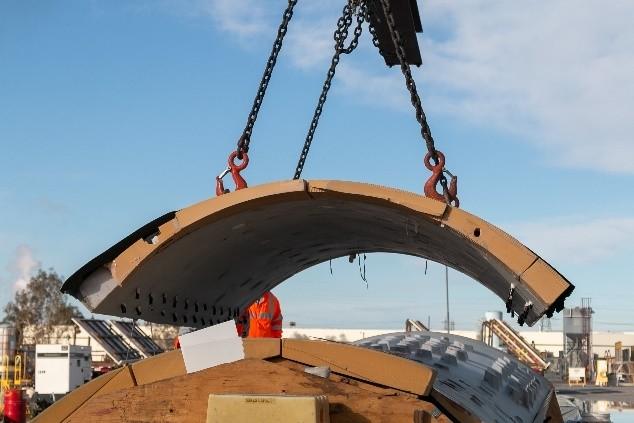
21 Douglas Noble, 2019. Untitled. [Digital Image]. Los Angeles, CA.
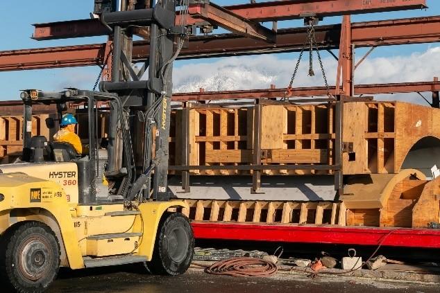
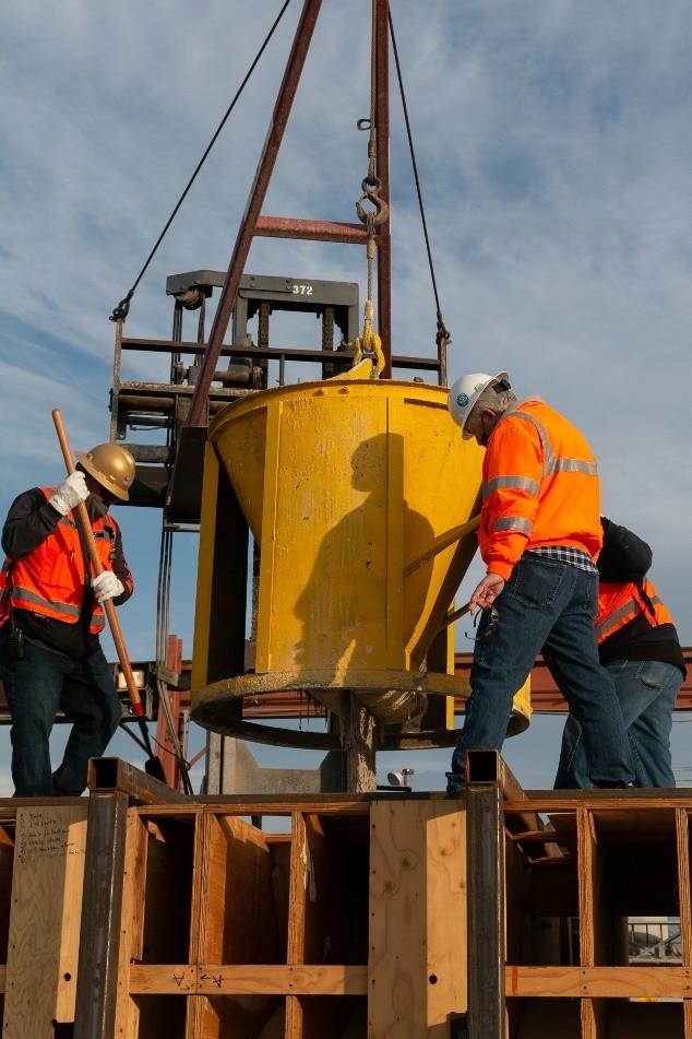
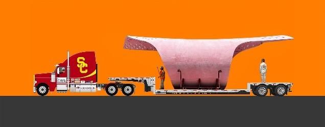 fig 1 | A construction drawing of the panel types as placed in the adaptablemold.
18 Kay Mashiach, 2019. Carapace fabrication drawing. [Digital Image]. Los Angeles, CA.
fig 2 | A collage of the built Carapace Pavilion in relation to human and transportation circumstances.
fig 1 | A construction drawing of the panel types as placed in the adaptablemold.
18 Kay Mashiach, 2019. Carapace fabrication drawing. [Digital Image]. Los Angeles, CA.
fig 2 | A collage of the built Carapace Pavilion in relation to human and transportation circumstances.
transporting it to Joshua Tree, and placing it on site. Either way, both options required the use of transporting with an oversized vehicle. The former solution was wider than a typical freeway lane, whereasthelatter,ifscaledcorrectly could meet the overpass height requirements and still fit widthwise withinalane.Thedeterminationwas that11.5-foot-diameterinthecenter and 13.5-foot-diameter at the edges wereidealvariablesforthispavilion. Resultant geometry was anticlastic, butthecurvatureitselfwasmildand graceful.
Shell Thickness
Ultra-High-Performance Concrete was chosen as the material of interest by Noble for its outstanding structuralcapabilities22.UHPCpushes the limits of formal expression with concrete, optimizing the amount of materialusedaswellasprovidingan ideal condition for complex shapes and free-form geometries23 . Exploitingthematerialtothehighest degree imparts extreme conditions including the absolute margins of thickness allowable24. Prerationalized25 in the algorithmic design generating process prompted an inclusion of a variable thickness componentlicensingprofileagency.
From the start, we collaboratively engaged an engineering company,
22 Block, Phillipe, Tom van Mele, Matthias Rippmann, Francesco Ranaudo, Cristián Calvo Barentin, and Noelle Paulson. “Redefining
Structural Art.” pp 69.
23 Pottmann, Helmut, Michael Eigensatz, Amir Vaxman, and Johannes Wallner. "Architectural geometry." pp 74 & 77.
24 Block, Phillipe, Tom van Mele, Matthias Rippmann, Francesco Ranaudo, Cristián Calvo Barentin, and Noelle Paulson. “Redefining
Structural Art.” pp 69.
25 Austern, Guy, Isaac Guedi Capeluto, and Yasha Jacob Grobman. “Rationalization.” pp 287.
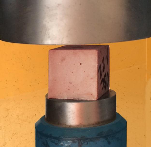
WalterP.Moore,tocomprehensively survey all possible structural capabilitiesofUHPC.LafargeHolcim, the company who developed the UHPC in the Carapace knew the strength capabilities, but never encounteredaprojectdealingwithit as the singular structural system. The engineers conservatively assumed the UHPC would attain 17,000 psi (117 MPa) compressive strength. Coupling determined compressive strength matched with our decisive structural shape optimality, the engineers calculated thatthepotentialminimumthickness applied to our shell structure is .5”. Removing the need for rebar as reinforcementprovidedasubstantial reduction in thickness. A typical thickness of concrete applied structurally ranges from 4.5” to 11”. Although these thicknesses are generalguidelines,itisonlyrelevant to vertical walls in a non-complex geometricalsystem.
FélixCandela’shyperbolicparaboloid vault employed in the underwater restaurant at L’Oceanogràfic in Valencia,Spainperformsathickness of ~2.5” that gradually increases towards the center and reaches a maximum of almost 9” at the intersection of ribs26. Although Candela’s projects are a larger scale than the shell structure of the Carapace, scalability doesn’t quite get employed in terms of concrete structural thickness. Clark Pacific evaluated a UHPC sample in a compressiontestafewmonthsafter wedeterminedourdesignandfound
26 Moreyra Garlock, Maria E., and Branko Glisic. “Thin Shell Concrete Structures of Félix Candela and Max Borges Jr..” Journal of the International Association for Shell and Spatial Structures 61, no. 1 (2020): 51–58.
https://doi.org/10.20898/j.iass.2020.203.031
that it reached a compressive strengthof25,000psi(172MPa).
Despite the allowed thickness of .5” applicable to our geometry, there werefurtherconstraintsthatneeded to be considered. Brainstorming methods such as a ‘male-female’ cast-in-place strategy or a side rail system led us to prescribe to a welding strategy. Noble involved the collaborative efforts of Jim Voss, the founderofthePCIFoundationaswell as JVI Inc., a company that develops connection hardware for precast/prestressed concrete. JVI developed an innovative connector calledthe‘Vector Connector’, meant as a flange connector to connect double tees within a precast structure.
29
Examining the vector connector’s implications in the Carapace, determined it as the most fitting proposal by far. Applying it to our model, with consultation and approval from the structural engineers displayed successful results but concluded that the shell thickness attheconnectionpointsis required to match the connectors, resulting in a 5.5” thickness. If modern, available fabrication systems matched the advancement of digital design complexity, the ultimate thickness of our structure would have been able to meet its absoluteminimumproperty.
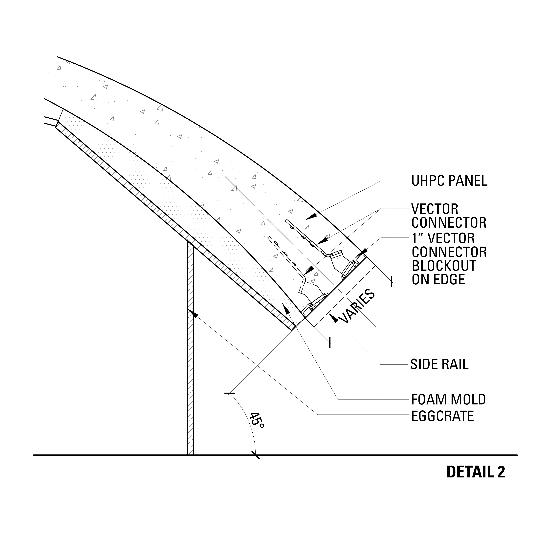
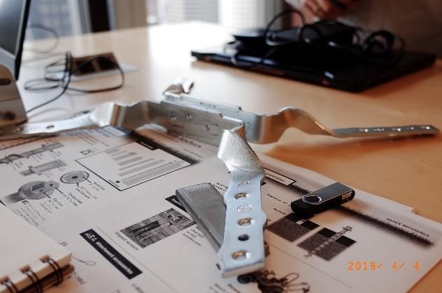 fig 3 | A UHPC block undergoing a compressive test at Clark Pacific.27
27 Douglas Noble, 2019. Carapace Stress Test [Digital Image]. Fontana, CA.
fig 4 | JVI Inc.'s Vector Connector28
Connector placements during castingproducedbyJVI.
28 Ivan Wong, 2019. JVI Vector Connector. [Digital Image]. Los Angeles, CA.
fig 3 | A UHPC block undergoing a compressive test at Clark Pacific.27
27 Douglas Noble, 2019. Carapace Stress Test [Digital Image]. Fontana, CA.
fig 4 | JVI Inc.'s Vector Connector28
Connector placements during castingproducedbyJVI.
28 Ivan Wong, 2019. JVI Vector Connector. [Digital Image]. Los Angeles, CA.
Although the determined edge thickness was optimized to meet 5.5”, we were able to reduce the thicknessatthecenterofthepanels due to our variable thickness rationalization embedded in the design algorithm30. We settled on a 1.5” thickness at the center of each panel. Collaborative efforts have provideduswithcontinuousdialogue and feedback loops to optimize the design process31, the structural integrity,andeaseoffabrication.The structural engineers evaluated the varied thickness strategy as ultimately advantageous in its compressiveperformance.
a basic architectural preference for its visual quality and functionality. Apertures enabled ventilation, sunlight, and reduction of material andloads33 .
Apertures
32
The Carapace pavilion originally prompted as a prototypical prefabricatedouthousesuggestedby Joshua Tree National Park Service, necessitates incorporating natural lighting conditions and ventilation systems in the case of an enclosed outhouse. Composing apertures was
30 Kotnik, Toni. “Digital Architectural Design as Exploration of Computable Functions.” pp 11. “The importance of an algorithmic description of the computational function, however, does not lie in the possibility of computing an optimal solution, but rather in the ability to control precisely the geometric relation between architectural elements under consideration.” (11)
31 Bhooshan, Shajay. “Architectural Geometry”. pp 3.
32 Douglas Noble, 2019. Untitled. [Digital Image]. Fontana, CA.
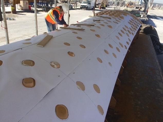
We devised a series of strategies, each exploring different shape and gridexpressionstakingadvantageof the computational tools that are highly accessible. We enabled a discrete, elementary script allowing us to test 2D geometric topologies that followed the formal and structural prescriptions of our resultant architecture35. With fabrication in mind, casting sharp corners revealed possible negative implications of panel removal from itsmold(seefig9).
33 Dombernowskt, Per, and Asbjørn Søndergaard. “Topology Optimisation”. pp 11.
34 Jeffery Cheung, 2019. Carapace Apertures [Digital Image]. Los Angeles, CA.
35 Ibid. pp 2.
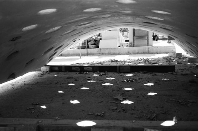
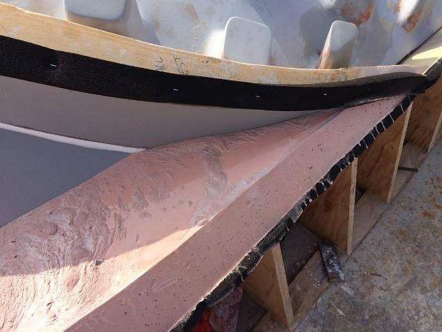
fig 6 | The resultant variable thicknessaftercasting.Requiring further fabrication driven design37, as brought to light by Brad Williams of Clark Pacific, we needed to consider the action of removing the cast. We designed the aperture systemasfiletedin2Danddecidedly applied it in 3D. However, our punctures in the shape were set perpendicularly to the curve. Removal of the cast with this figuration is unlikely. Resolving this meant we needed extrusion in an equivalent direction for all apertures -directionallyparalleltotheremoval.
These collaborative feedback loops display the absolute necessity of interdisciplinary dialogue throughout theentiredesignprocess40
Fabrication Formwork

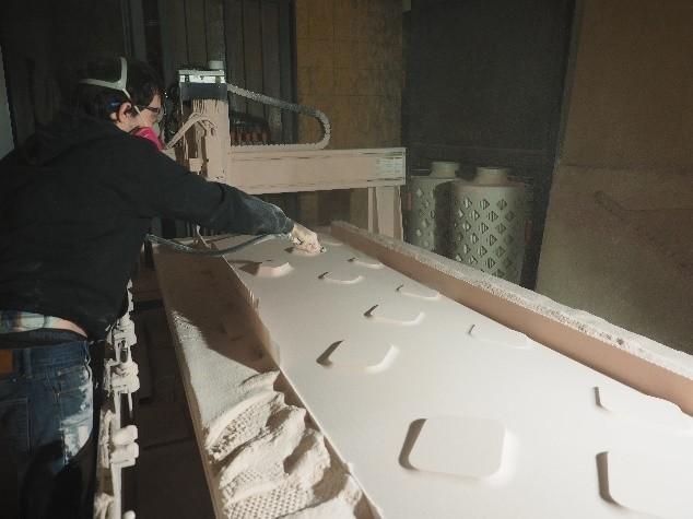
UHPCnecessitatedtheuseofamold that could evolve to fit the needs of variable panels. The development of the Carapace’s mold deployed the useofpolyurethanefoamandaCNC mill, a robotic fabrication system automating architectural
36 Douglas Noble, 2019. Untitled. [Digital Image]. Fontana, CA.
37 Austern, Guy, Isaac Guedi Capeluto, and Yasha Jacob Grobman. “Rationalization.” pp 286.
38 Douglas Noble, 2019. Failed Carapace Cast [Digital Image]. Fontana, CA.

39 Kay Mashiach, 2021. Shadow Play in the Carapace. [Digital Image]. Fontana, CA.
40 Dombernowskt, Per, and Asbjørn Søndergaard. “Topology Optimisation”. pp 7.
41 Douglas Noble, 2019. Untitled. [Digital Image]. Fontana, CA.
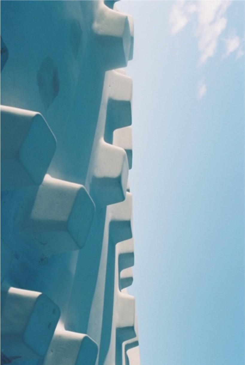
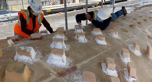
fig 8 | Test cast of the aperture andcavitysystems.36 fig 9 | Failed cast depicting the sharpcornerconditions.38 fig 10 | A roof panel after mold extraction.39 fig 11 | Cavities on the wall panels.41production42. Designing a mold flexible to different circumstances meant implicating removable blockouts. The aperture system provided a means of variability throughout the panels – each panel had its own corresponding set of blockouts. The wall and foundation panels contained cavities guided by the geometrical grid expression, while the roof panels enabled a mixtureofaperturesandcavities.
pour, a layer of silicon resin along with a layer of mold release was sprayed onto the mold with the relevantblockouts.
Aneggrate systemwas employedto produce the formwork for the Carapace Pavilion. We utilized computational tools in collaboration with Clark Pacific to employ an appropriate formwork structure. Unfortunately, calculations of predictive discrepancy were lacking, inducing mismatch with the foam mold. The eggrate needed to be rebuilt, causing a setback for construction.
43
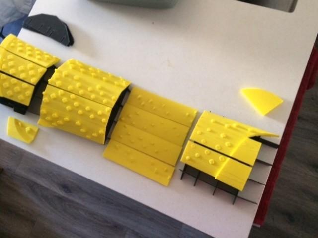
Asthegeometrywastoolargetobe castusingonefoamboard,asystem ofpanelizationwasdevised.Aseries of 16 foam panels comprised the total mold. Except for a few blockouts for cavities repeated on eachpanel,eachblockoutneededto be removable. The results were messy, though, as the bit did not permit a high resolution. Almost 30 student volunteers joined in to sand the mold as well as label and place blockouts accordingly. When casting each panel, the blockouts were then corresponded to a specific location onthemoldandattachedusingclay and silicon paste. Before each panel
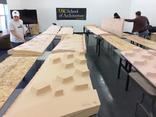 fig 12 | A 3D print of the speculative foam panelization andeggcrate.
42 Block, Phillipe, Tom van Mele, Matthias Rippmann, Francesco Ranaudo, Cristián Calvo Barentin, and Noelle Paulson. “Redefining Structural Art”. pp 68.
43 Douglas Noble, 2019. Untitled. [Digital Image]. Fontana, CA.
fig 13 | CNC milling of the foam panels.44
fig 14 | Foam panels laid out and sanded with the help of volunteers.45
44 Ivan Wong, 2019. Zach at the CNC Mill. [Digital Image]. Los Angeles, CA.
fig 12 | A 3D print of the speculative foam panelization andeggcrate.
42 Block, Phillipe, Tom van Mele, Matthias Rippmann, Francesco Ranaudo, Cristián Calvo Barentin, and Noelle Paulson. “Redefining Structural Art”. pp 68.
43 Douglas Noble, 2019. Untitled. [Digital Image]. Fontana, CA.
fig 13 | CNC milling of the foam panels.44
fig 14 | Foam panels laid out and sanded with the help of volunteers.45
44 Ivan Wong, 2019. Zach at the CNC Mill. [Digital Image]. Los Angeles, CA.
Ultra-High-Performance Concrete
CastingUHPCwas anexperimenton its own. Lafarge Holcim was in constant communication throughout the design conception and more importantly, during the casting
process49. They understood UHPC’s structural capabilities in a datadriven sense, recognizing the numerical performance, however never observing UHPC implemented in a purely structural capacity. LafargeHolcimwascuriousastothe performanceofcomplexity.
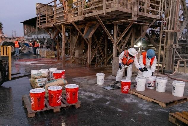
The ingredients sent by Lafarge Holcim included the very fine aggregate and separate from the steelfibers.Thisprovideduswiththe ability to determine our own structural expression: the percentage of fibers to aggregate that we include determines its structuralperformance. Ourmixwas 2:1 (not including water or pigment) of aggregate and steel fibers, respectively. The UHPC was mixed and poured onsite at Clark Pacific. Countless employees worked on this project for the mere experiencesake51 – learning to cast UHPC on a complex form was a huge opportunity52. The employees at Clark Pacific wielded their precast
49 Bhooshan, Shajay. “Collaborative Design: Combining Computer-Aided Geometry Design and Building Information Modelling.” Architectural Design 87, no. 3 (2017): 82–89. https://doi.org/10.1002/ad.2177. Pp 85.
50
pp 2.
51 Bhooshan,
fig 15 | Determining locations of foamblockouts46 fig 16 | Attempting toseamlessly attach blockouts in preparation foraroofpanelcast.47 fig17|Totalformworkonsite48 46 Douglas Noble, 2019. Carapace Blockout Organization. [Digital Image]. Fontana, CA. 47 Douglas Noble, 2019. Placing Blockouts. [Digital Image]. Fontana, CA. 48 Kay Mashiach, 2020. Clark Pacific Reveal Day [Digital Image]. Fontana, CA. fig 18 | Buckets of UHPC aggregate and steel fibers preppedforthefirstcastatClark Pacific.50 Kay Mashiach, 2020. UHPC for the Carapace’s First Pour. [Digital Image]. Fontana, CA.tools including specialty cranes, large scale pouring systems, and shake tables (for removing air bubbles). All these tools and machines helped us to better understandthediscrepancybetween UHPC and traditional concrete. We discovered in the first pour, that the metal fibers tended to fall to the bottom. Through a trial-and-error process53, we devised the optimal mix of UHPC’s constituent materials. Thenextpourprovedsuccessful.
Conclusion
Thegoalofthispaperwastooutline the process of implementing a concept such as Architectural Geometry in a small-scale project. Successfully relevant in both the worldofacademiaandtheindustry55 , the Carapace employed an interdisciplinary rigor that became self-evident in motivating a collaborative approach throughout architectural projects. After an indepth evaluation of the Carapace, the applicability and value of Architectural Geometry is quite evident.
Structural Art”. pp 67.
53
Though the automated process of planning fabrication as well as collaborative commentary and design proved effective in fabrication,ittookovertwoyearsto fabricate due to unforeseen issues that arose in its constructability paired with the pandemic. After a long process of fabrication, the Carapace is fully assembled and being prepared for transportation and installation in Joshua Tree NationalPark,expectedinMay2022.
fig 19 | Employees of Clark Pacific cast the UHPC in the formwork.54 52 Block, Phillipe, Tom van Mele, Matthias Rippmann, Francesco Ranaudo, Cristián Calvo Barentin, and Noelle Paulson. “Redefining Bhooshan, Shajay. “Architectural Geometry”. pp 3. 54 Kay Mashiach, 2020. Carapace First Pour. [Digital Image]. Fontana, CA. fig 20 | Completed fabrication of theCarapacePavilion.56 55 Austern, Guy, Isaac Guedi Capeluto, and Yasha Jacob Grobman. “Rationalization.” pp 288.Collaboration
Countless individuals, companies, and disciplines sought to provide collaborativeeffortsfortheCarapace Pavilion, as to impart their knowledge but even more so to capitalize on the experimentation engagement.TheCarapaceprovided an academic outlook on architecture which deals in innovation and deviation of the typical procedures recorded in the industry. However, the project also situated itself on a deliberate platform intended to explore the ability of implementing rigorous and complex systems in a real-worldpractice.
Recognition
Acknowledgementsmustbegivento everyone involved including Clark Pacific, JVI, Lafarge Holcim, Clark Construction, Cresset, PCI West, PCI Foundation, Walter P. Moore, and countless student and faculty volunteers. The Carapace recently won the 2022 Precast Concrete Institute Design Award for Best Custom Solutionaswellas the2021 American Institute of Architects, Los Angeles Citation Award for Installations.
57 “Reinforcement.” PCI Journal 67, no. 1 (January 2022).
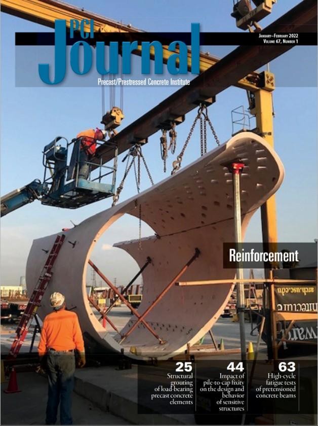 fig 21 | The cover of the PCI Foundation Journal featuring the CarapacePavilion.57
Bibliography
1 Austern, Guy, Isaac Guedi Capeluto, and Yasha Jacob Grobman. “Rationalization Methods in Computer Aided Fabrication:ACriticalReview.”
AutomationinConstruction 90 (March 14, 2018): 281–93.
https://doi.org/10.1016/j.autco n.2017.12.027.
2 Bhooshan, Shajay. “Architectural Geometry and Tacit AI.” London: Architectural Association Design Research Lab and Zaha Hadid Computation and Design Group,2021.
3 Bhooshan, Shajay. “Collaborative Design: Combining ComputerAided Geometry Design and Building Information Modelling.” Architectural Design 87, no. 3 (2017): 82–89.
https://doi.org/10.1002/ad.217 7
4 Billington, DavidP., andMaria, M. Garlock. “Thin shell concrete structures: the master builders.” Journal for the International Association for Shell and Spatial Structures 45,no.3(2004):147-155.
5 Block, Phillipe, Tom van Mele, MatthiasRippmann,Francesco Ranaudo, Cristián Calvo Barentin, and Noelle Paulson. “Redefining Structural Art: Strategies, Necessities and Opportunities.” Structural
Engineer 98, no. 1 (January 2020):66–72.
6 Dombernowskt, Per, and Asbjørn Søndergaard. “ThreeDimensional Topology Optimisation in Architectural ...” Threedimensional topology optimisation in architectural and structural design of concretestructures. Accessed February 11, 2022.
http://fluxstructures.net/_artikl er/artikel_iass.pdf.
7 Kotnik, Toni. “Digital Architectural Design as Exploration of Computable Functions.” International Journal of Architectural Computing 8, no. 1 (2010): 1–16.
https://doi.org/10.1260/14780771.8.1.1
8 Licklider, J. C. “Man-Computer Symbiosis.” IRE Transactions on Human Factors in Electronics HFE-1, no. 1 (March 1960): 4–11.
https://doi.org/10.1109/thfe2.1 960.4503259
9 Moreyra Garlock, Maria E., and Branko Glisic. “Thin Shell Concrete Structures of Félix Candela and Max Borges Jr..”
Journal of the International Association for Shell and Spatial Structures 61, no. 1 (2020): 51–58.
https://doi.org/10.20898/j.iass.
2020.203.031
10 National Park Service, Management of National Park Service Programs. Department oftheInteriorandNationalPark Service:(2006).
11 Pottmann, Helmut, Michael Eigensatz, Amir Vaxman, and Johannes Wallner. "Architectural geometry." Computers & graphics 47(2015):145-164.
12 Salazar, Jaime, and Manuel de Landa. “Philosophies of Design: The Case of Modeling Software.” Essay. In Verb Processing: Architecture Boogazine,132–42.Barcelona: Actar,2001.
List of Figures
fig 22 Aconstructiondrawingofthe panel types as placed in the adaptablemold.
Kay Mashiach, 2019. Carapace fabrication drawing. [Digital Image].LosAngeles,CA.
fig 23 A collage of the built Carapace Pavilion in relation to human and transportation circumstances.
Douglas Noble, 2019. Untitled. [Digital Image]. Los Angeles, CA.
fig 24 A UHPC block undergoing a compressivetestatClarkPacific.
Douglas Noble, 2019. Carapace Stress Test. [Digital Image]. Fontana,CA.
fig 25 JVIInc.'sVectorConnector
Ivan Wong, 2019. JVI Vector Connector. [DigitalImage].Los Angeles,CA.
fig 27 The resultant variable thicknessaftercasting.
Douglas Noble, 2019. Untitled [DigitalImage].Fontana,CA.
fig 28 Apertureideation
Jeffery Cheung, 2019. Carapace Apertures.[DigitalImage].Los Angeles,CA.
fig 29 Testcast oftheapertureand cavitysystems.
Douglas Noble, 2019. Untitled. [DigitalImage].Fontana,CA.
fig 30 Failed cast depicting the sharpcornerconditions.
Douglas Noble, 2019. Failed Carapace Cast. [Digital Image].Fontana,CA.
fig 31 A roof panel after mold extraction.
KayMashiach,2021. ShadowPlayin theCarapace. [Digital Image]. Fontana,CA.
fig 32 Cavitiesonthewallpanels.
Douglas Noble, 2019. Untitled. [DigitalImage].Fontana,CA.
fig 26 A detail of the Vector Connectorplacementsduringcasting producedbyJVI.
JVI Inc, 2019. Vector Connector in theCarapace. [Digital Image]. Lincolnwood,IL.
fig 33 A 3D print of the speculative foampanelizationandeggcrate.
Douglas Noble, 2019. Untitled. [Digital Image]. Los Angeles, CA.
fig 34 CNC milling of the foam panels.
Ivan Wong, 2019. ZachattheCNC Mill. [Digital Image]. Los Angeles,CA.
fig 35 | Foam panels laid out and sandedwiththehelpofvolunteers.
Douglas Noble, 2019. A little help from our Carapace friends. [Digital Image]. Los Angeles, CA.
fig 36 Determininglocationsoffoam blockouts
Douglas Noble, 2019. Carapace BlockoutOrganization. [Digital Image].Fontana,CA.
fig 37 Attempting to seamlessly attach blockouts inpreparation fora roofpanelcast.
Douglas Noble, 2019. Placing Blockouts. [Digital Image]. Fontana,CA.
Kay Mashiach, 2020. CarapaceFirst Pour.[DigitalImage].Fontana, CA.
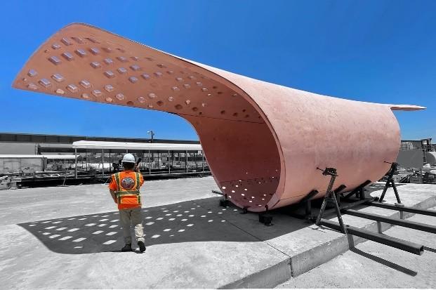
fig 41 Completed fabrication of the CarapacePavilion.
Douglas Noble, 2021. Final Assembly. [Digital Image]. Fontana,CA.
fig 42 The cover of the PCI Foundation Journal featuring the CarapacePavilion.
“Reinforcement.” PCIJournal 67, no. 1(January2022).
Kay Mashiach, 2020. Clark Pacific Reveal Day. [Digital Image]. Fontana,CA.
fig
Kay Mashiach, 2020. UHPC for the Carapace’sFirstPour. [Digital Image].Fontana,CA.
fig 38 Totalformworkonsite 39 Buckets of UHPC aggregate and steel fibers prepped for the first castatClarkPacific. fig 40 Employees of Clark Pacific casttheUHPCintheformwork.