kay mashiach portfolio 2018 - 2023 www.kaymashiach.com
contents
halokinesis AA DRL society nano AA DRL out of stock AA DRL timber tower USC SoA carapace pavilion USC SoA 01 02 03 04 05
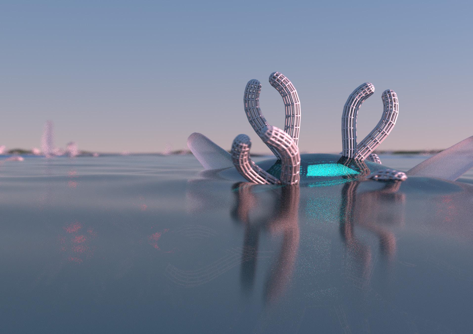
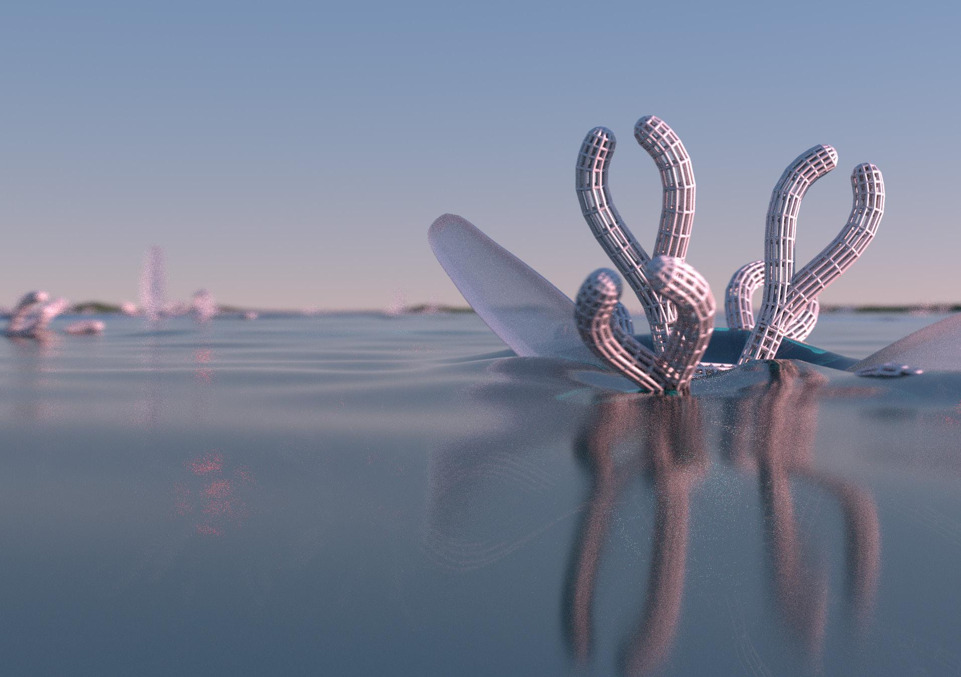
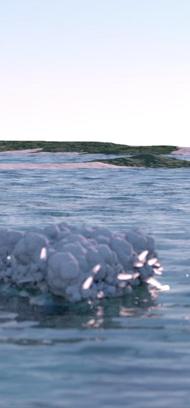
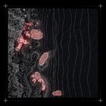
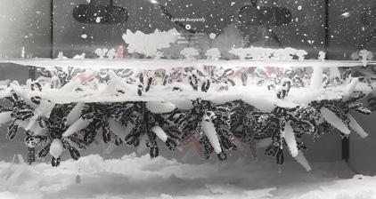
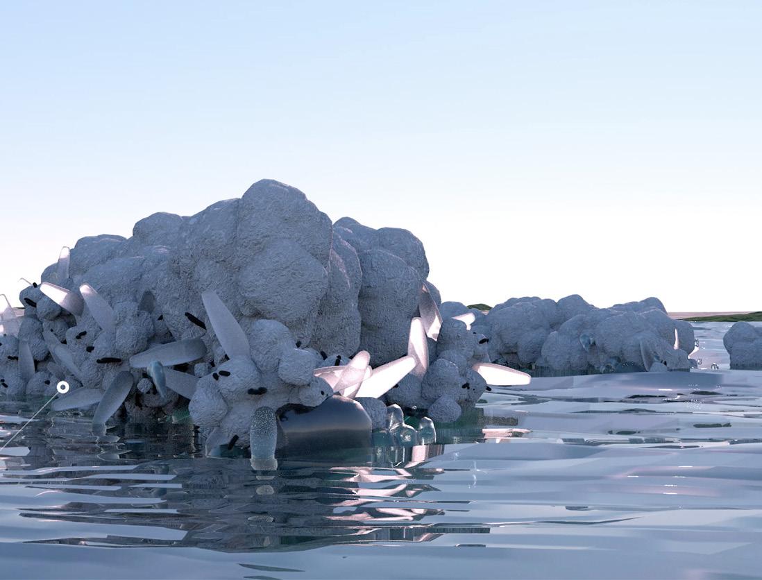
HALOKINESIS is an architectural endeavor that utilizes salt, a universal material, to re-balance coral colonies and locally eradicate coral bleaching within applicable locations.
HALOKINESIS is the magical ability to move salt with one’s mind, and thus, this project explores salt crystallization’s phenomenology by harnessing this power within our reality.
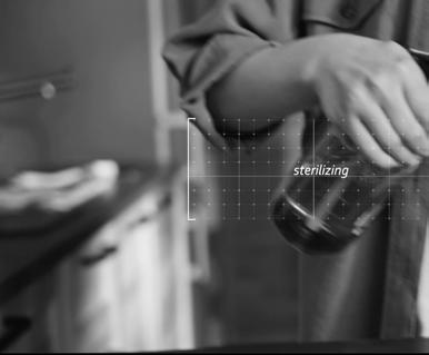
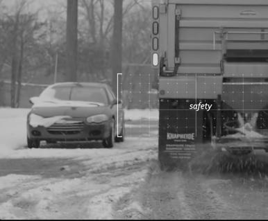
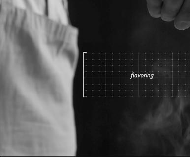

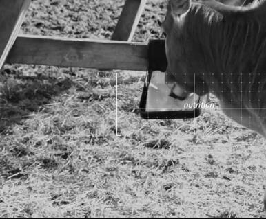
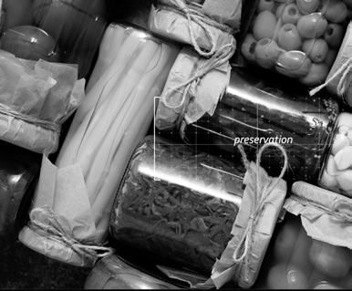
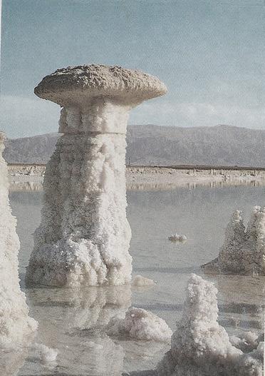
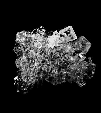
Salt, an essential and abundant element on earth, is known for its ubiquitous flavoring and preservation, while also denoted as a sterilizing agent. However, salt remains a vital element of life. Salinity’s decreasing ocean density in relation to its paradoxical attributes of sustaining and annihilating situates itself as a priority in investigating its usefulness and applications.
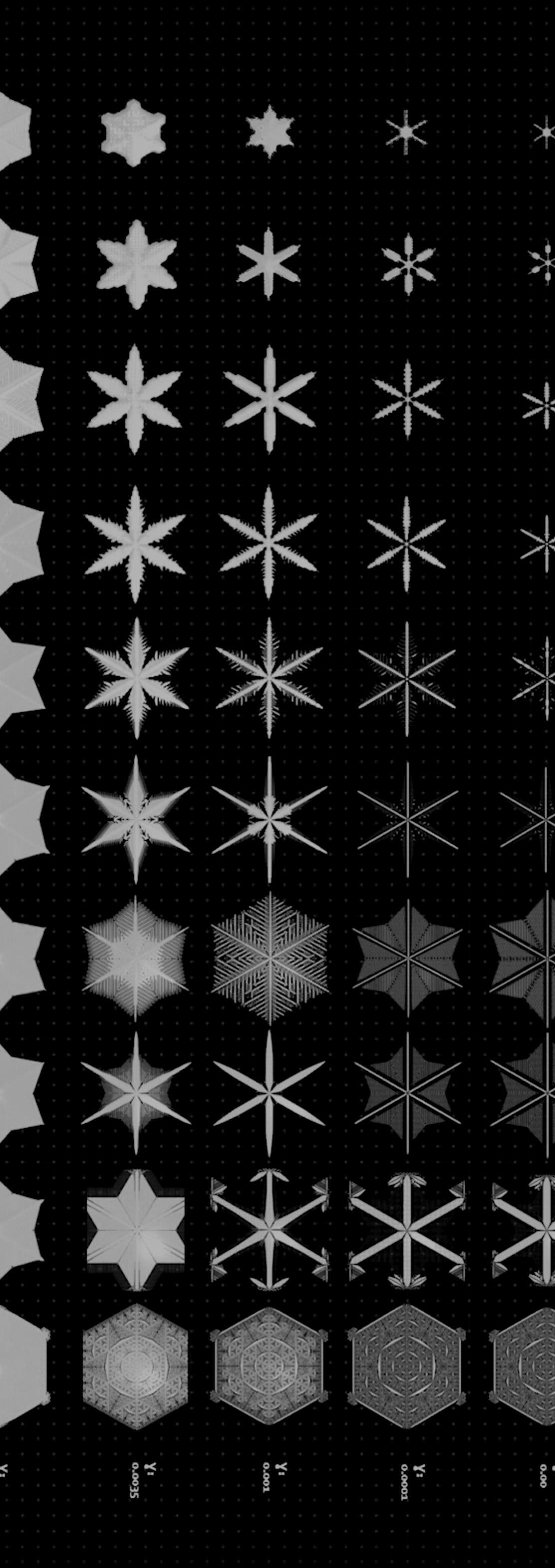
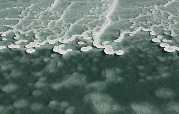
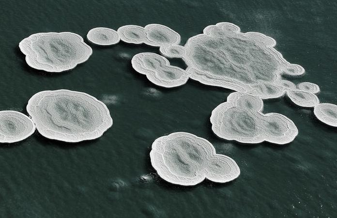
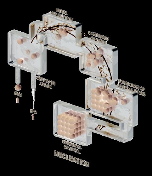
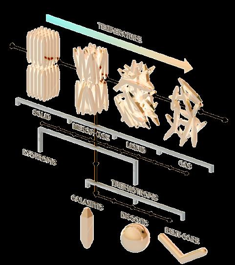
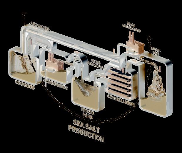
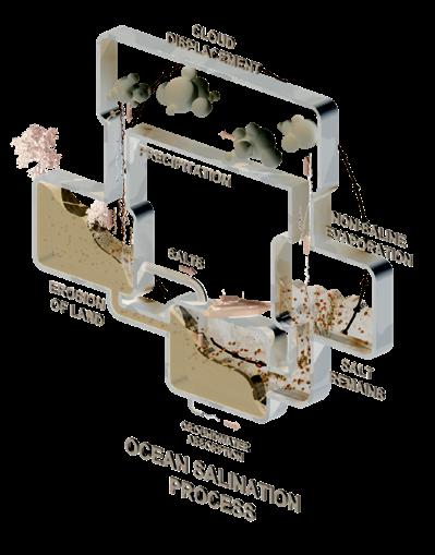
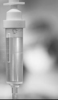
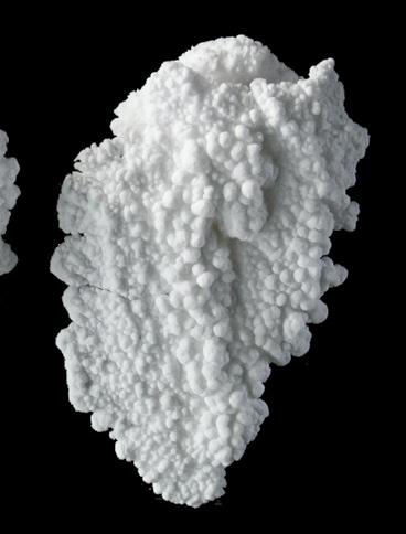
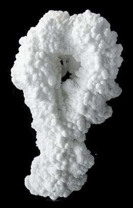
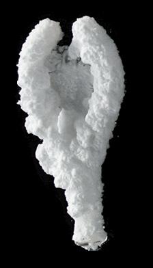
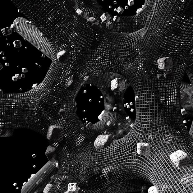
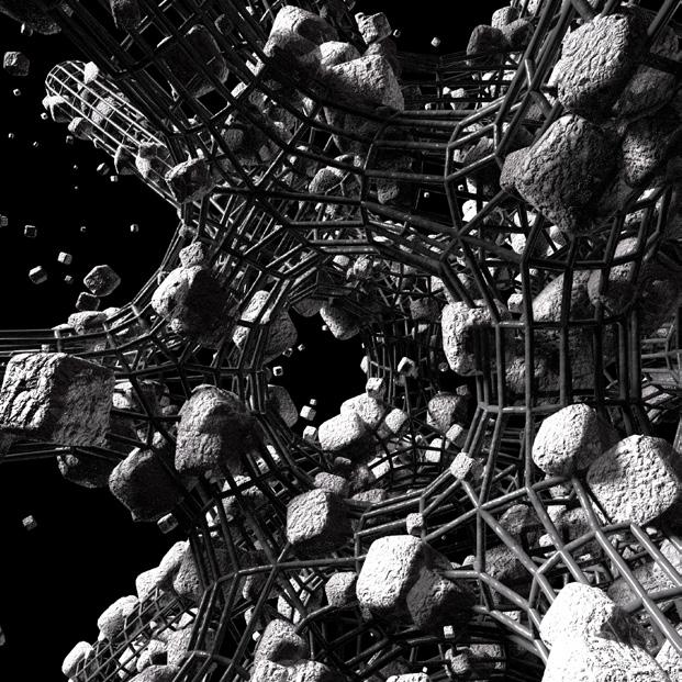
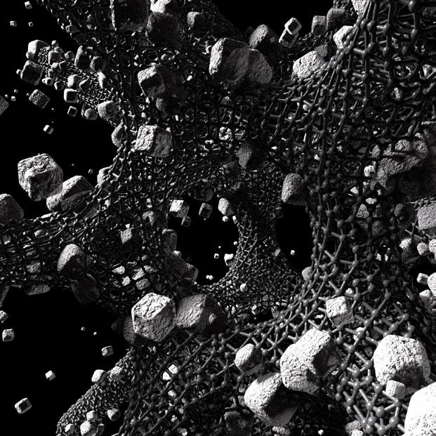
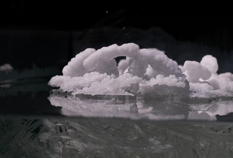
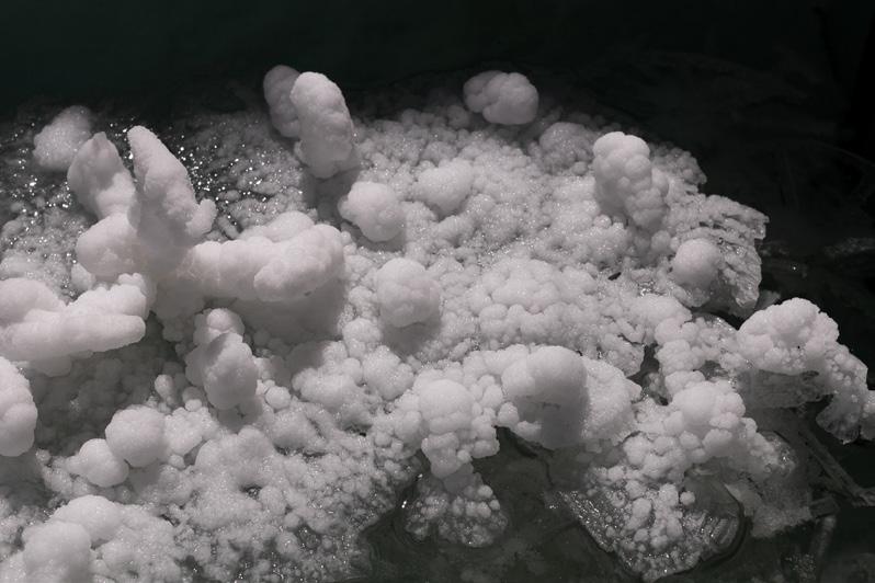
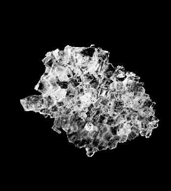
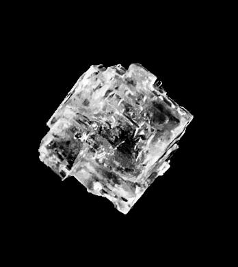
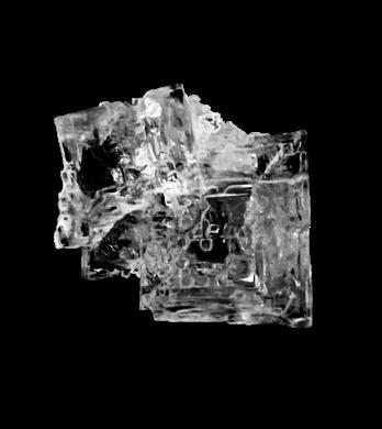
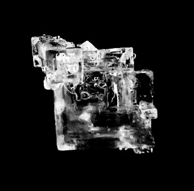
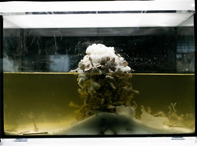
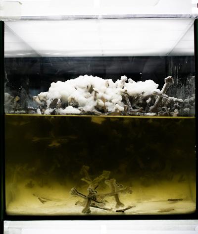
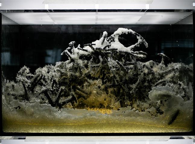
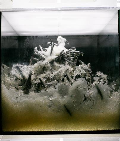
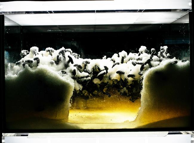
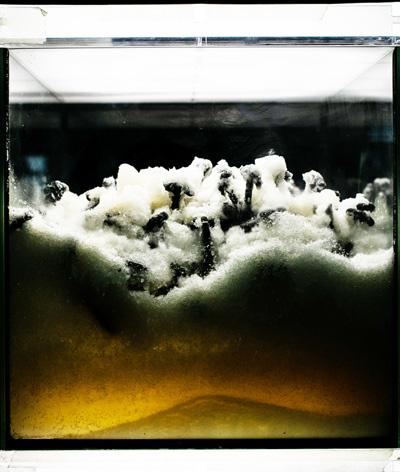
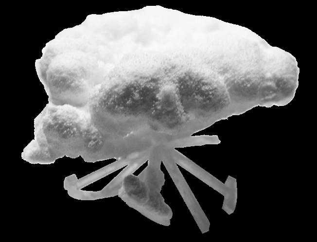
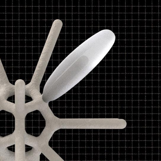
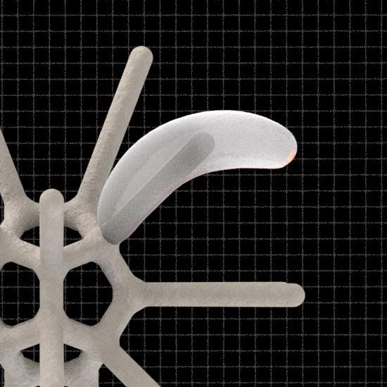
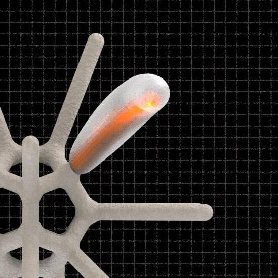
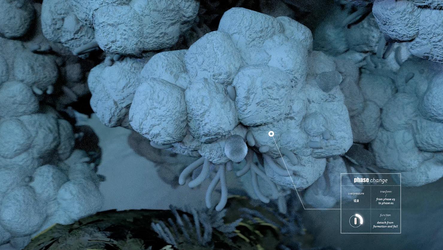
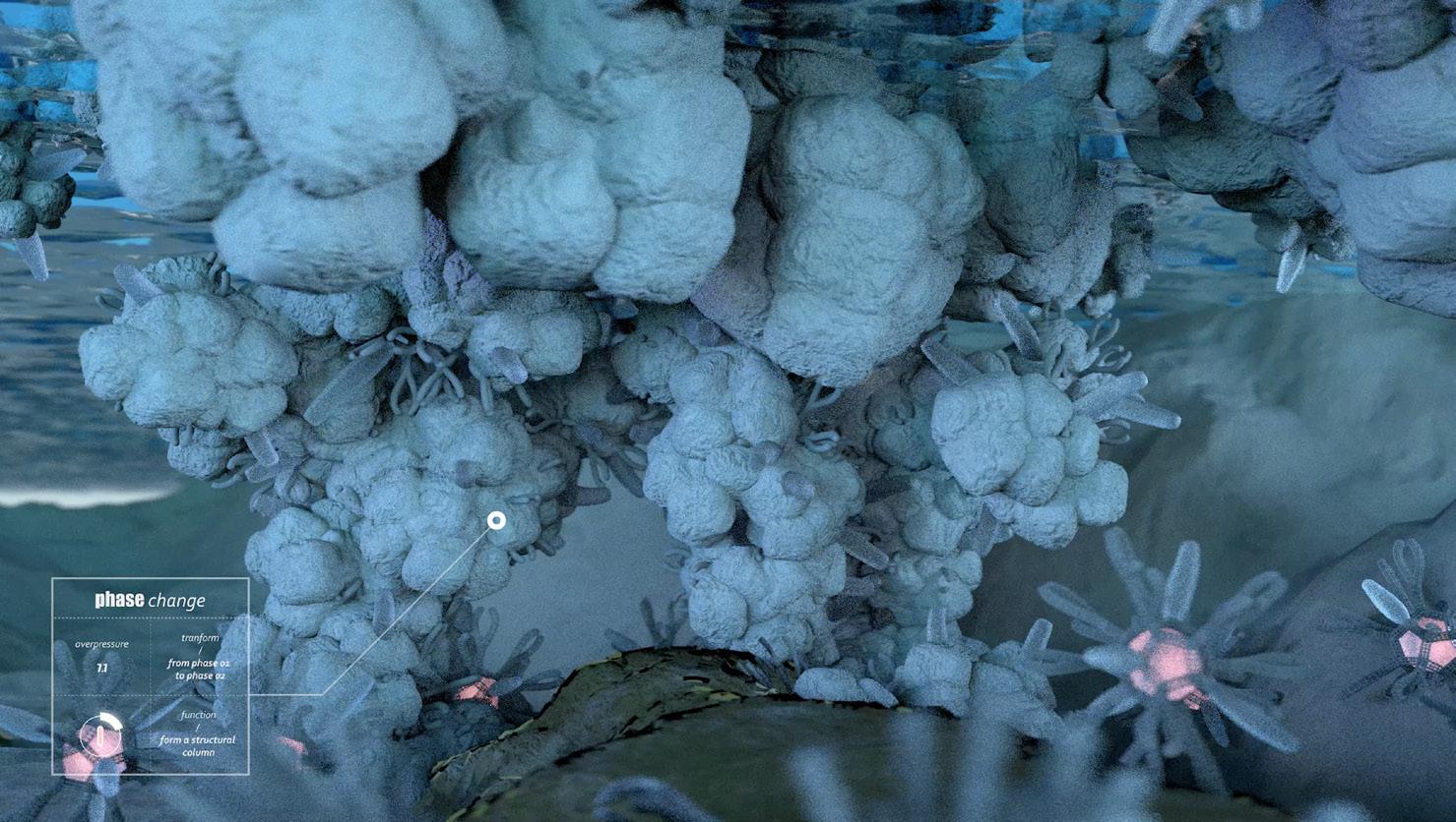
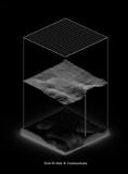
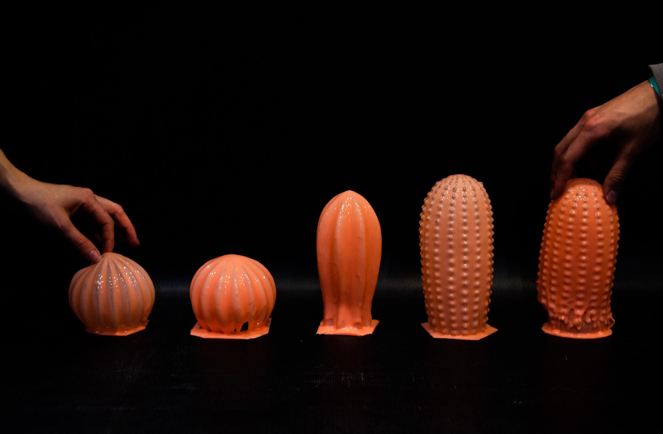
Our elemental was focused on salt. Focusing our experimental manifestations around appropriation of the origins of salt production processes, both natural and artificial, we revealed this element as holding an inherent nature of super-temporal growth. This required us to elicit interventions through controlling behavioral propagation. As we further identified salt to be a keystone to the ecological processes of the world, we took into consideration the circulation and movement of salt bodies on earth (halokinesis). Our HALOKINESIS relied on time, coupled with a responsive scaffold, growing crystals to achieve strength and formations. Salt tectonics, halokinesis, and crystallization are typically referred to as existing within a geological time scale.

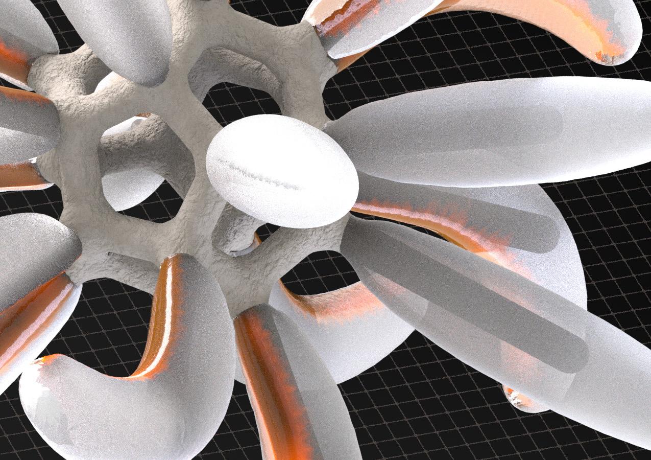
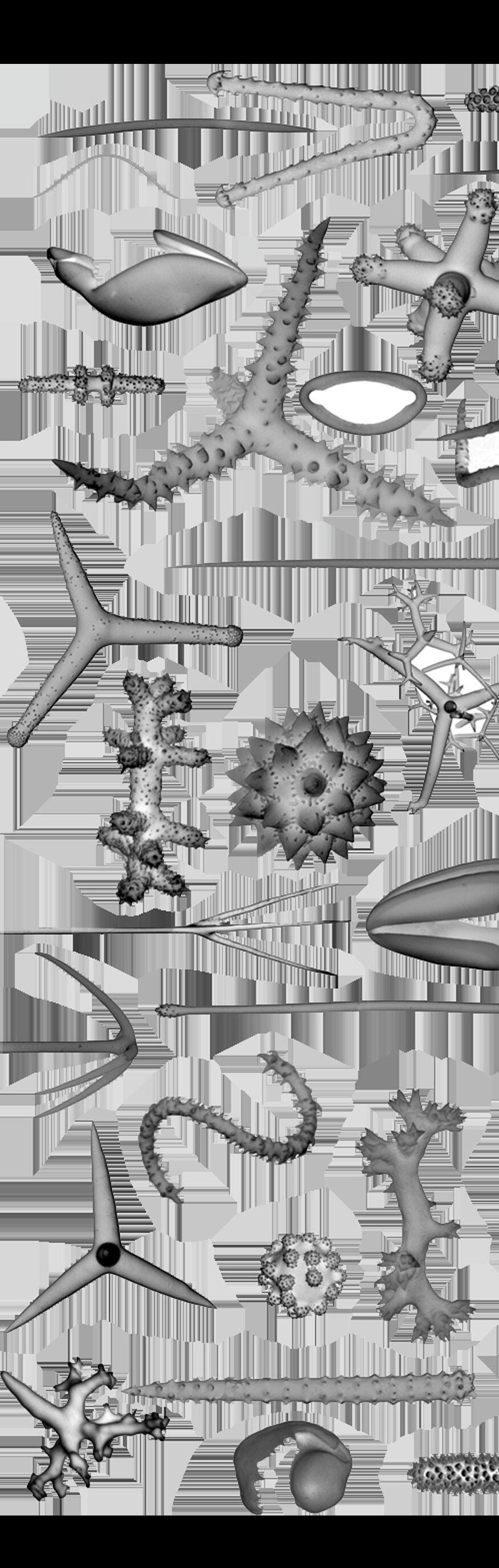
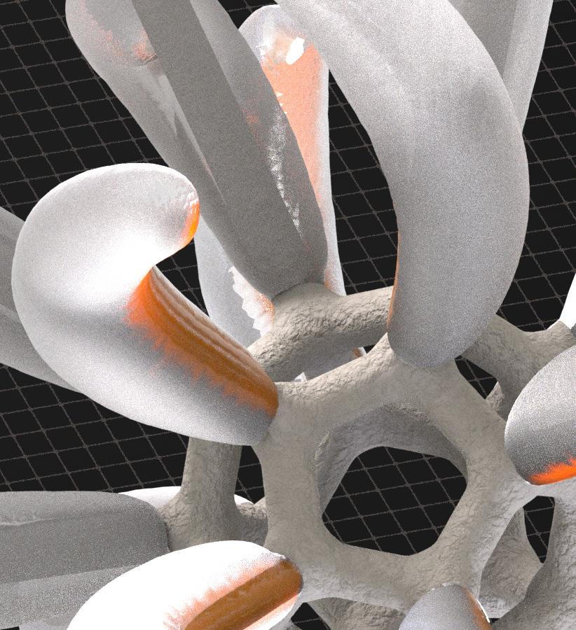
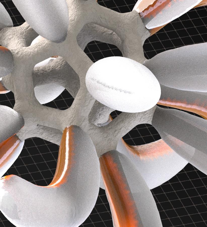
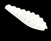
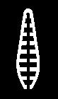
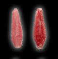
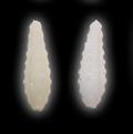
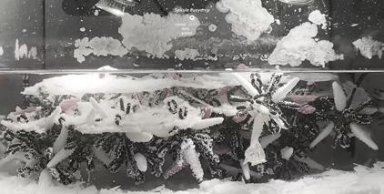
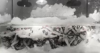
On the basis of research, we identified two different processes that would influence crystallization: solution-related and scaffold-related. Our controlled-variable approach led to the spicule scaffold, which outperformed all other scaffold types as spicules entangled with each other, forming robust structures.
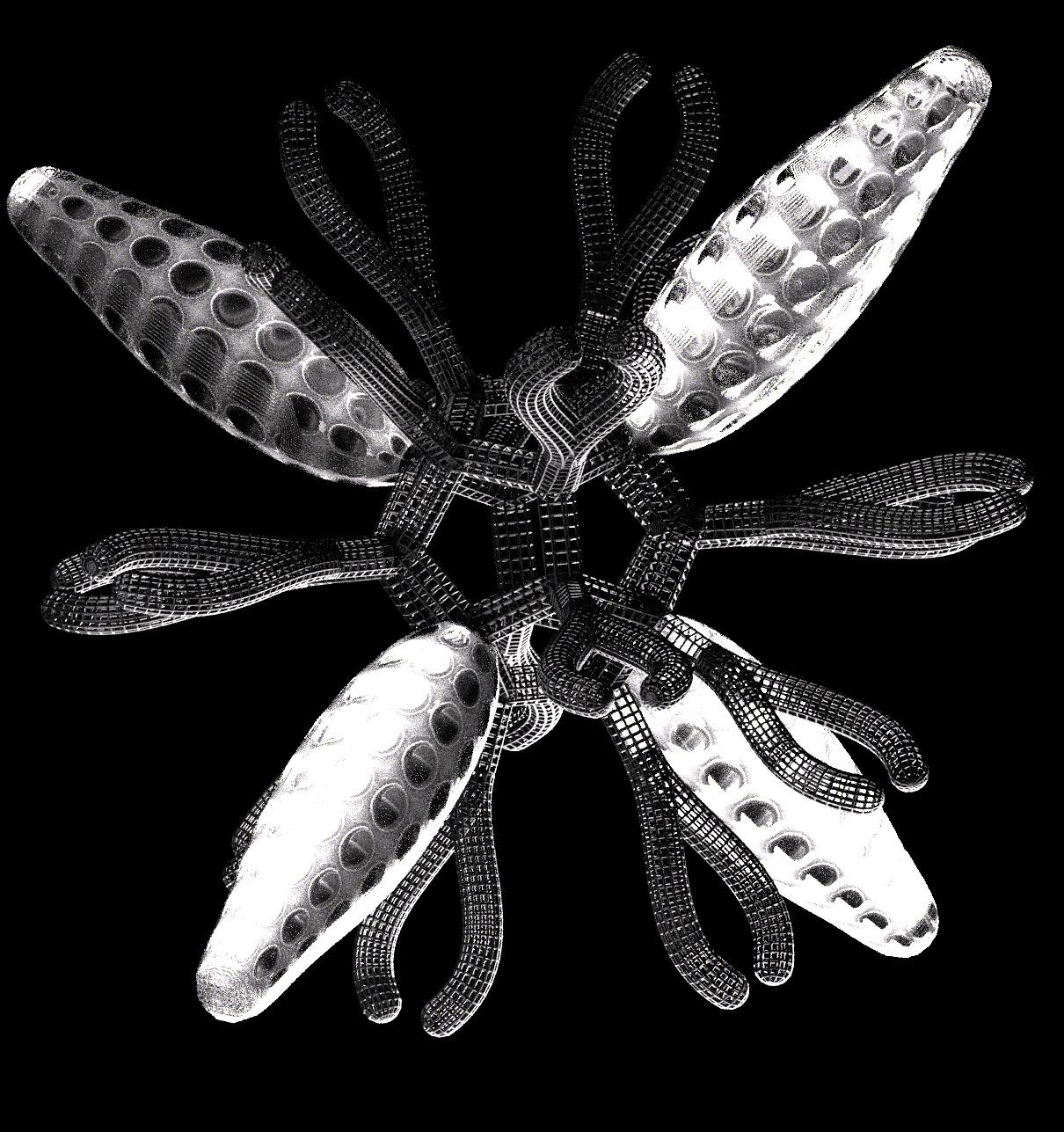
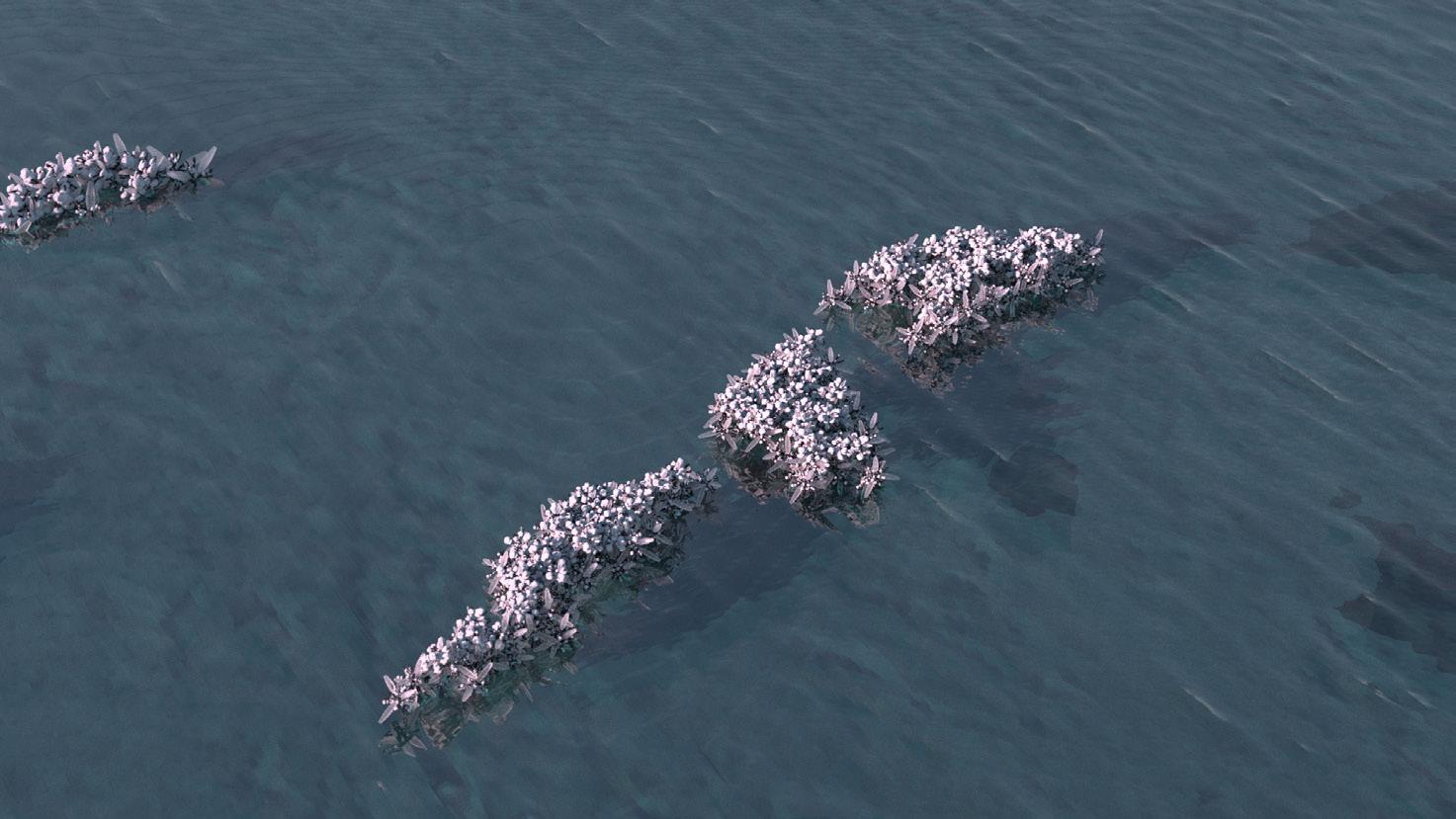
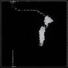
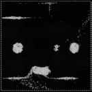
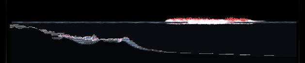
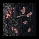
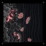
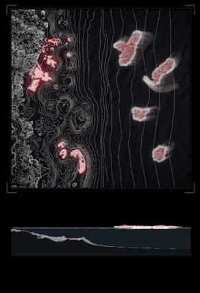
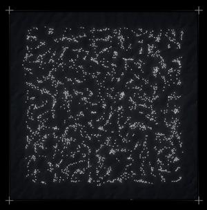
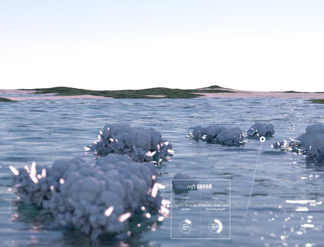
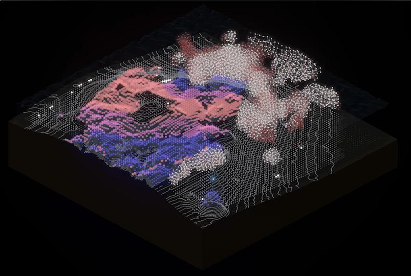
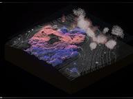
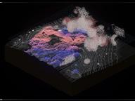
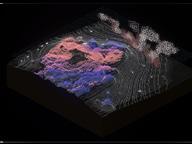
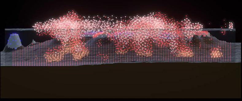
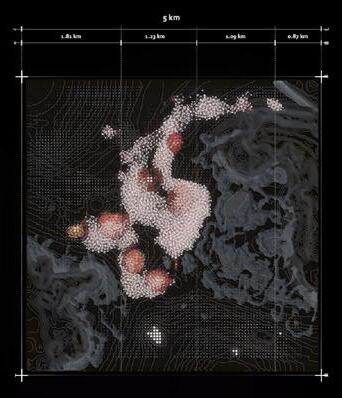
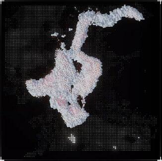
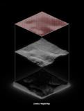
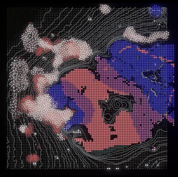
In the 'unlimited solution’ of the ocean, salt is in superabundance, becoming the site for HALOKINESIS. By designing and embedding intelligent systems, our goal was to create a system that receives environmental data to determine agent behavioral patterns, adapting to external forces from the continuous and substantial environmental variability. Following the information flow, a structure would be generated by the swarming behavior that constantly interacts with local organisms and terrain.
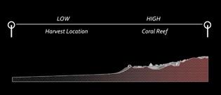
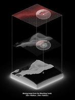
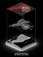
By implementing a cyclical system of crystallized agents that rehabilitate coral reefs through the introduction of higher salinity levels, HALOKINESIS gives agency to the scaffold in order to determine ideal formations.
https://issuu.com/kaymashiach/docs/phase_02_booklet_final_issuu

https://youtu.be/hBAt_7Z0UNY
halokinesis AA DRL
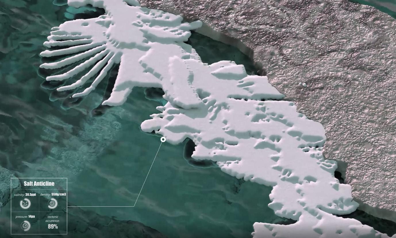

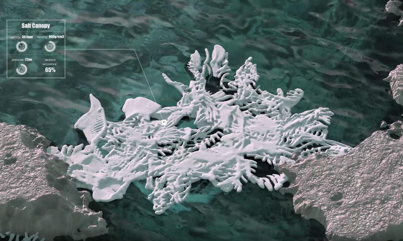

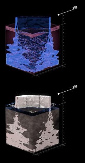
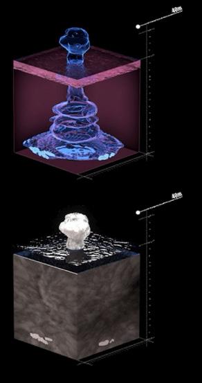
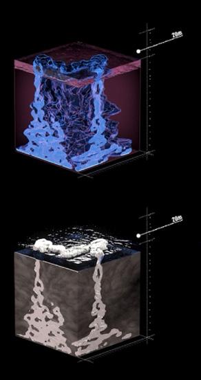


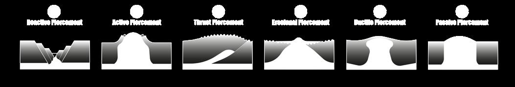
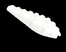
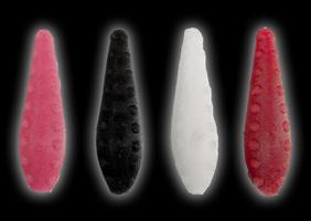
Salt Canopy Salt Wall Salt Anticline Salt Roller Salt Pillow Salt Sheet Salt Stock Salt Teardrop HALOKINESIS TYPOLOGIES SUBSURFACE PIERCEMENT salt+tectonics
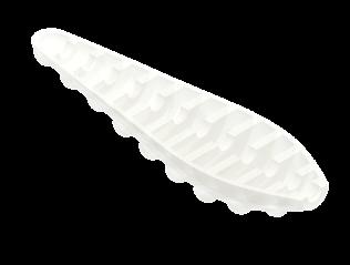
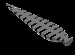
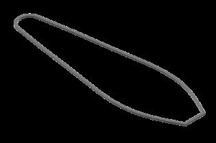
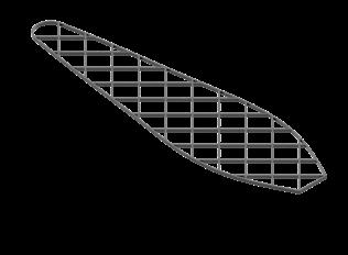
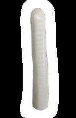
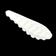
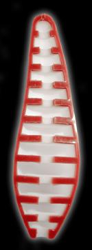
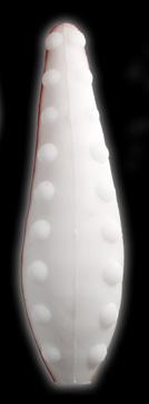
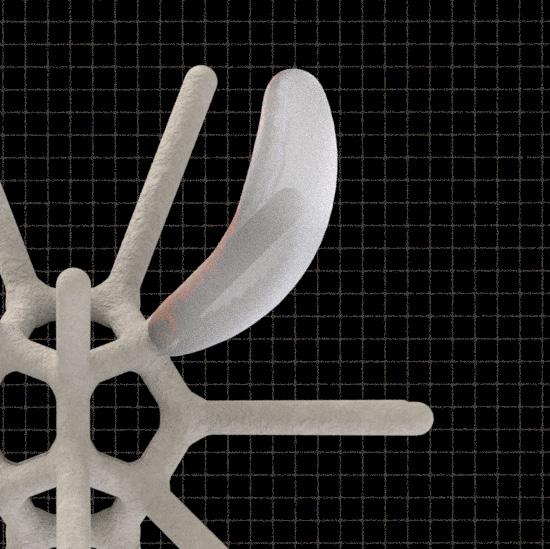
spicule+scaffold


COMBINED ARMS PNEUMATICS Branch Type T-End Branch Type _ Arc-End Branch Type _ Fork-End 2 DAYS 5 DAYS 8 DAYS 10 DAYS
CORE

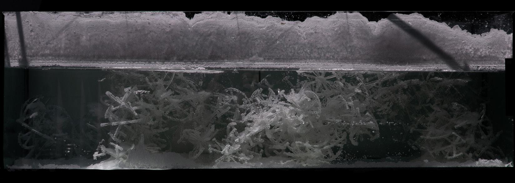
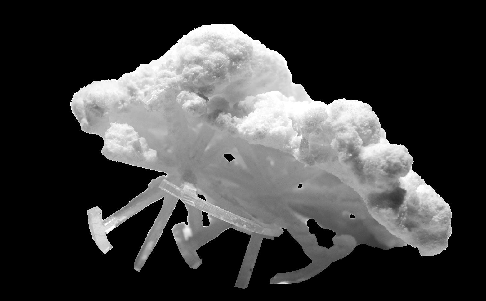
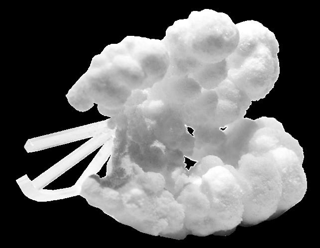
 crystallized spicule wall that is sustained under water
crystallized spicule bridge that can bear weight and withstand water impact
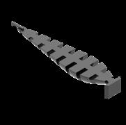
crystallized spicule cave that sustains a cavernous roof structure
1/2 spicule
1 spicule
3 spicules
crystallized spicule wall that is sustained under water
crystallized spicule bridge that can bear weight and withstand water impact
crystallized spicule cave that sustains a cavernous roof structure
1/2 spicule
1 spicule
3 spicules
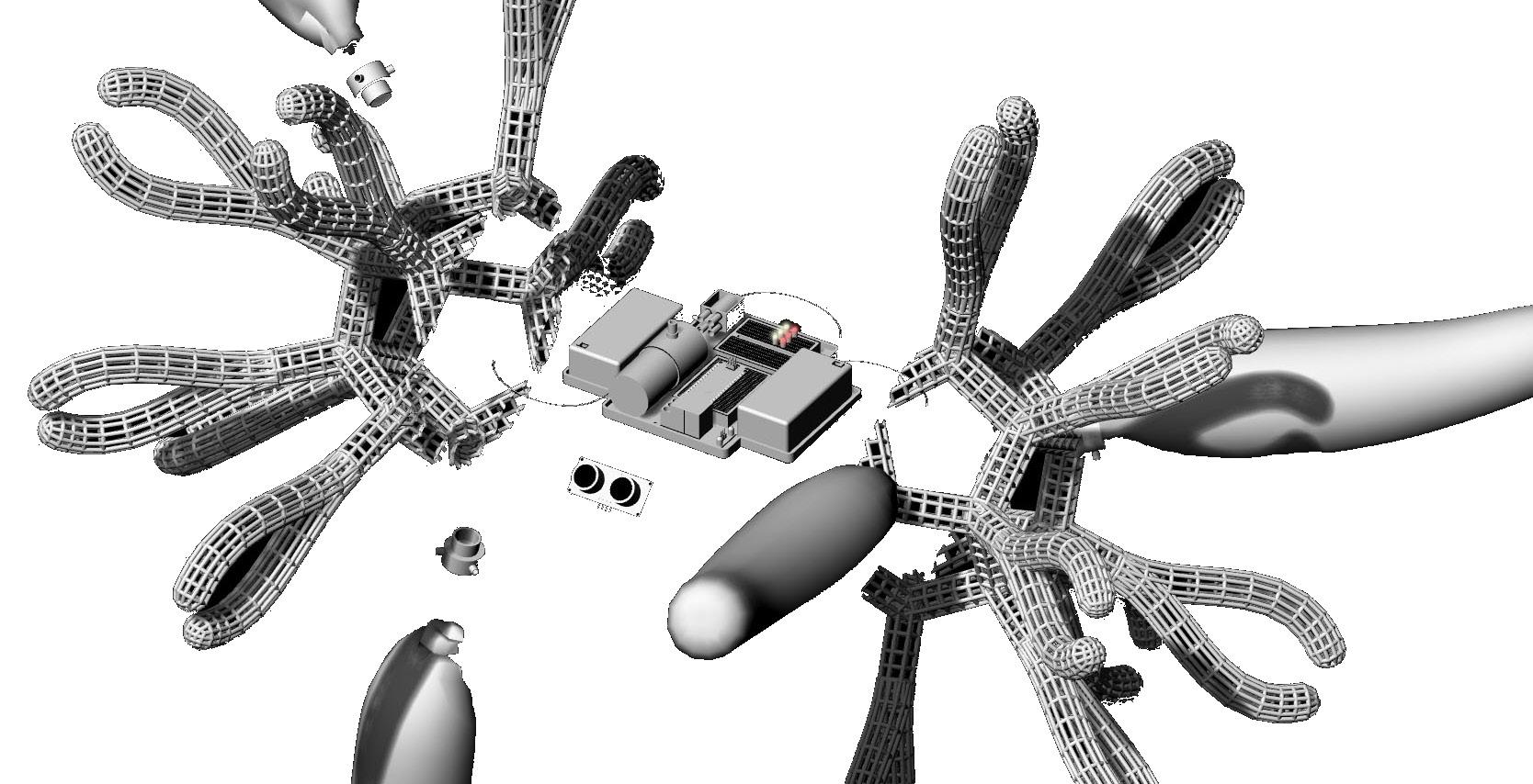


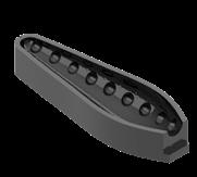
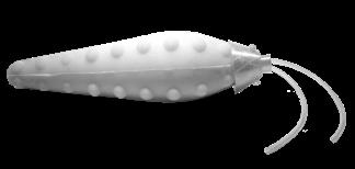
1 2 5 4 6 7 3 9 10 8 Air pump Air valve Ultrasonic sensor Batteries LED lights Arduino Nano Relay Connector Pneumatic Spicule 1 2 3 4 5 6 7 8 9 10 1.5x 23.3x 30x 6.4x 10x prototype 01 pneumatics raft pneumatics formational pneumatics prototype 02 pneumatics agent
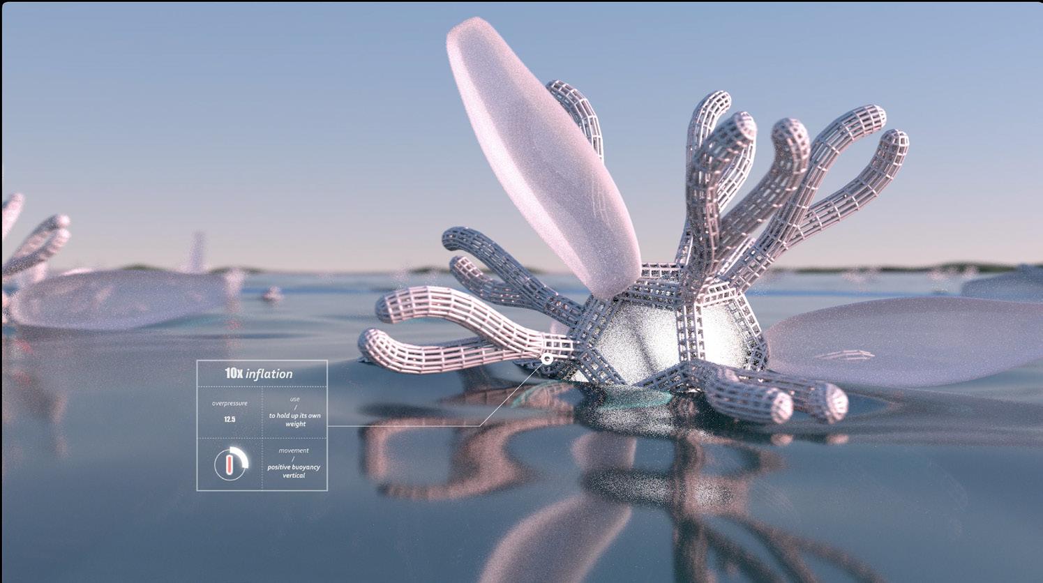
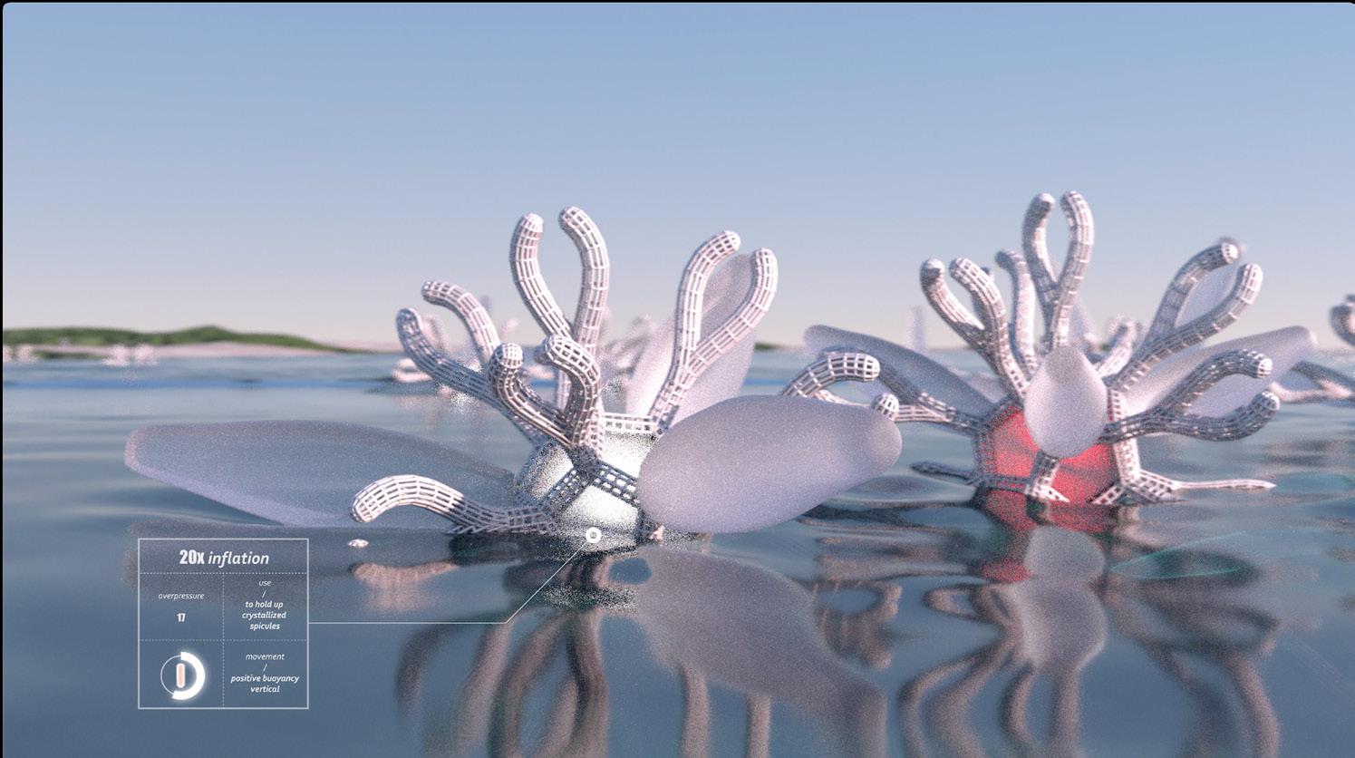
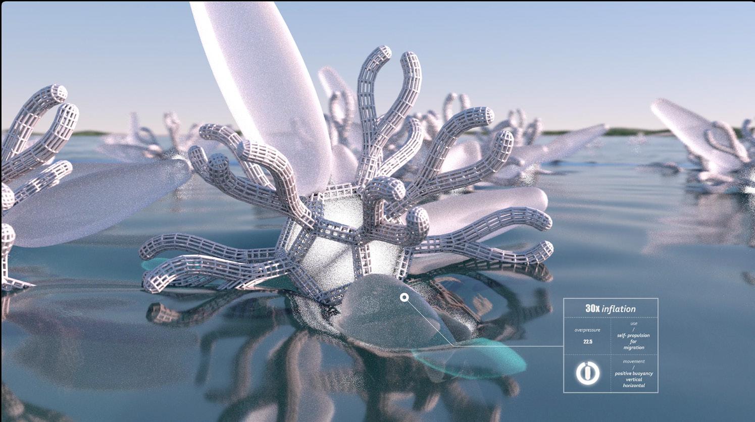


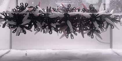
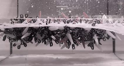
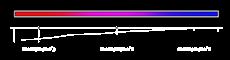
PHASE 00 negative buoyancy PHASE 02 positive buoyancy
01 neutral buoyancy PHASE 03 self-propulsion 01 1.5x negative buoyancy ability to lift multiple spicules ability to lift multiple crystallized spicules 6.4x neutral buoyancy 10x positive buoyancy 04 03 02
PHASE
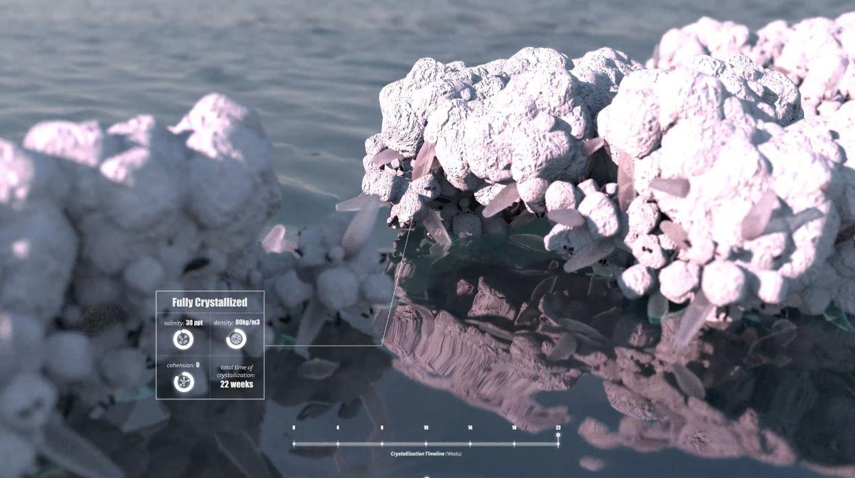
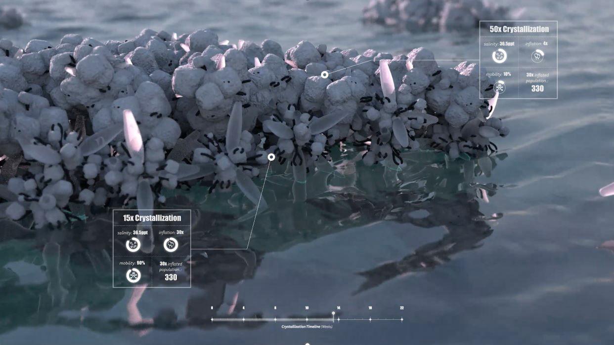


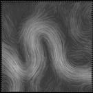
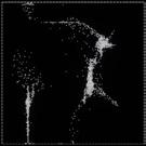
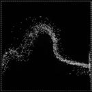
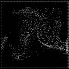
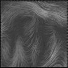
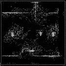
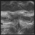

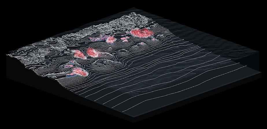
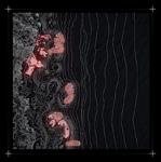
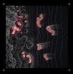
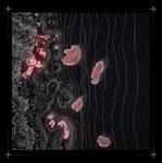


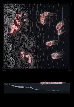
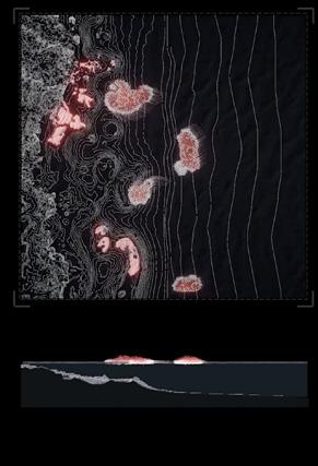

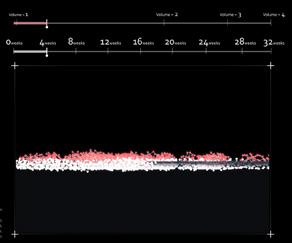
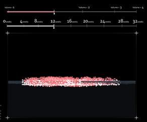
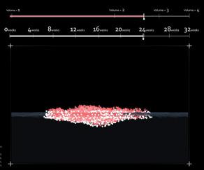
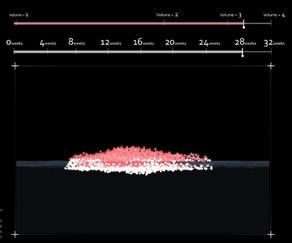
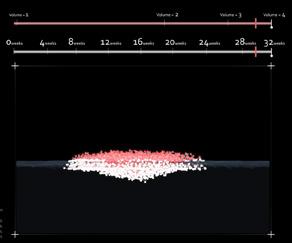


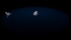
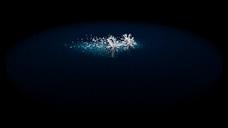

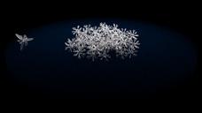


Current Variation_1 Current Speed = 1.21 m/s; Agent Population = 4000; Self - propulsion Force = 20; Current Variation_2 Current Speed = 0.85 m/s; Agent Population = 4000; Self - propulsion Force = 20; Current Variation_2 Current Speed = 0.85 m/s; Agent Population = 4000; Self - propulsion Force = 20; using heat lamp time 0 days _ estimated natural time 1 days using heat lamp time 2 days _ estimated natural time 4 days using heat lamp time 4 days _ estimated natural time 9 days using heat lamp time 12 days _ estimated natural time 20 days using heat lamp time 9 days _ estimated natural time 14 days 3 days 7 days 15 days 20 days 30 days Harvest Time = 4 weeks; Ratio = 1:0.1; Harvest Time = 12 weeks; Ratio = 1:0.7; Harvest Time = 24 weeks; Ratio = 1:2.6; Harvest Time = 28 weeks; Ratio = 1:3; Harvest Time = 32 weeks +; Ratio = 1:4+; curved path active spicules passive spicules 2 active spicules 1 passive spicules 50 active spicules 4 passive spicules 50 straight path active spicules 1 passive spicules 2 active spicules 1 passive spicules 50 active spicules 4 passive spicules 50 migration harvest


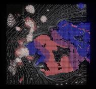

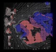
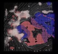
Time Frame _ 31 hours Time Frame _ 102 hours Time Frame hours Time Frame: 132 hours Time Frame: hours Time Frame: hours stigmergy+pollination migration
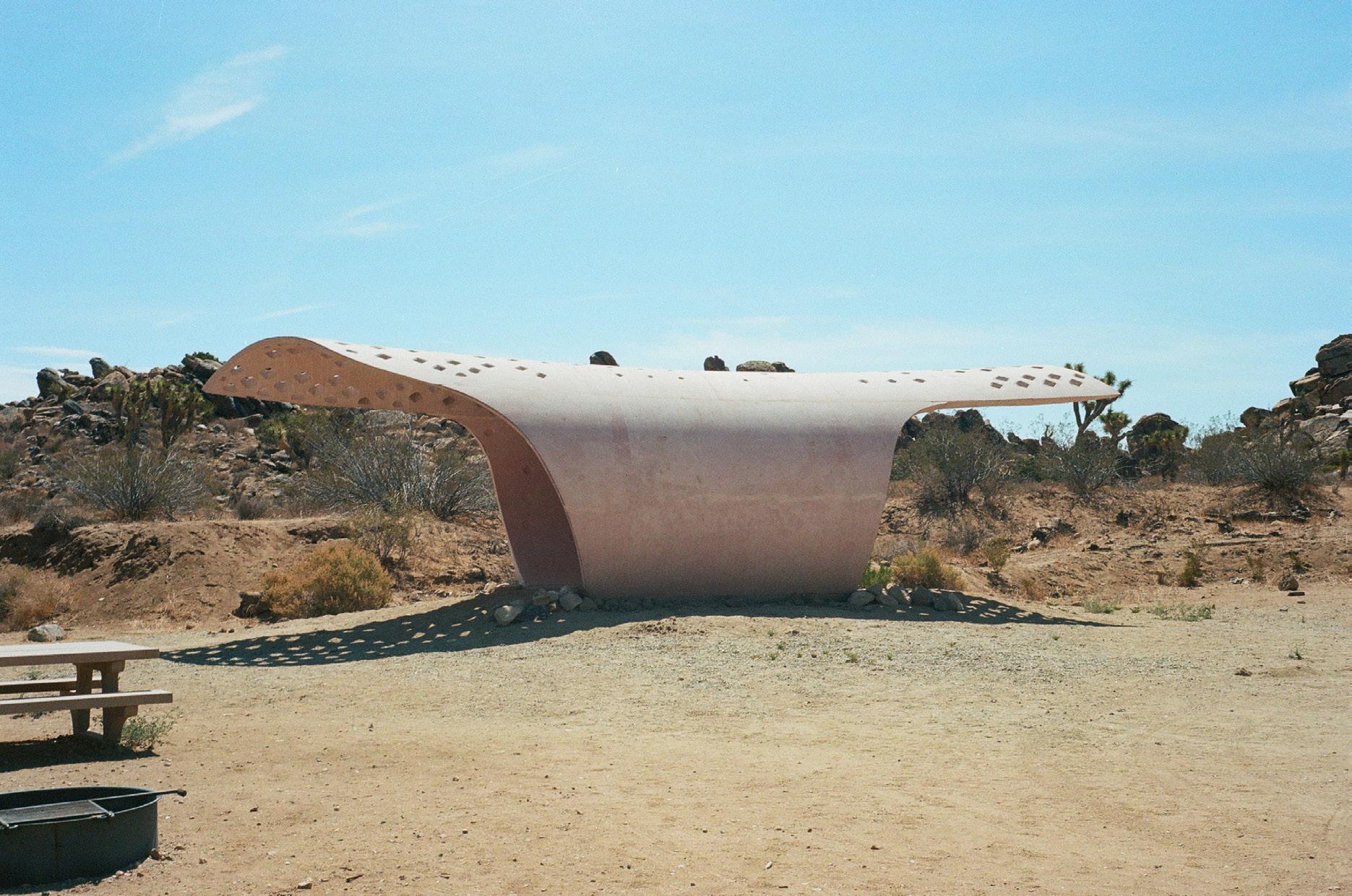
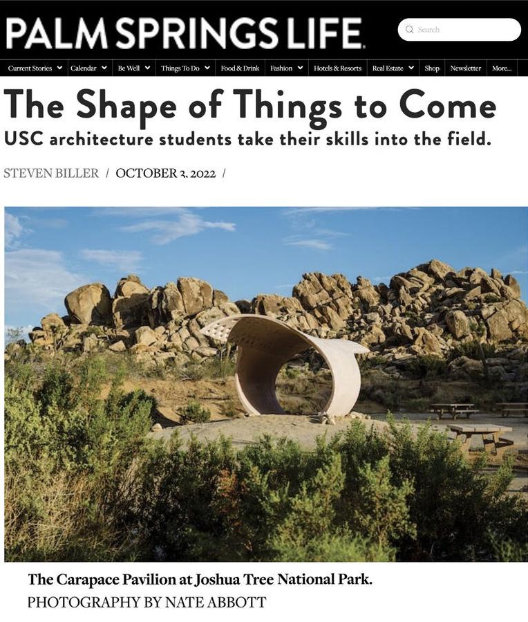
carapace pavilion
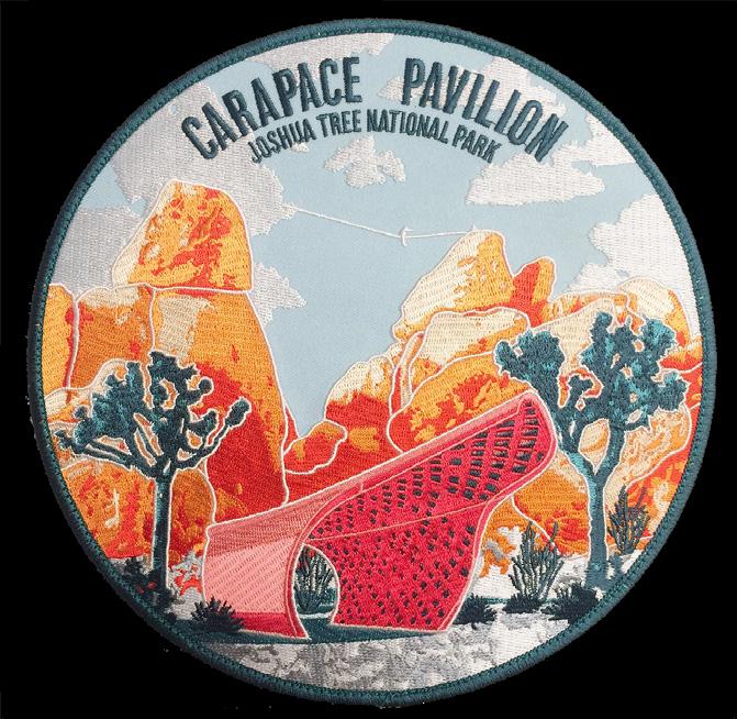
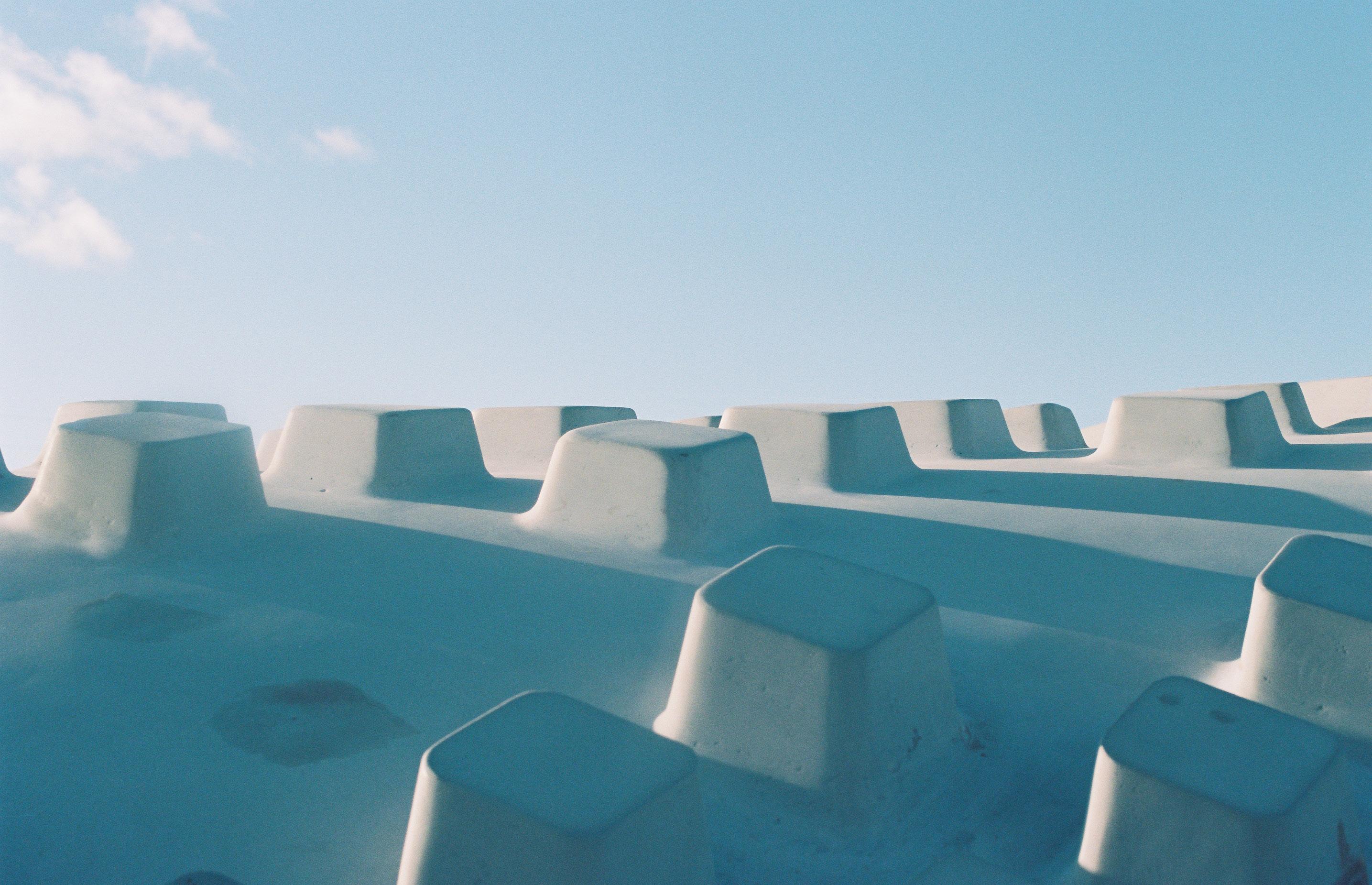
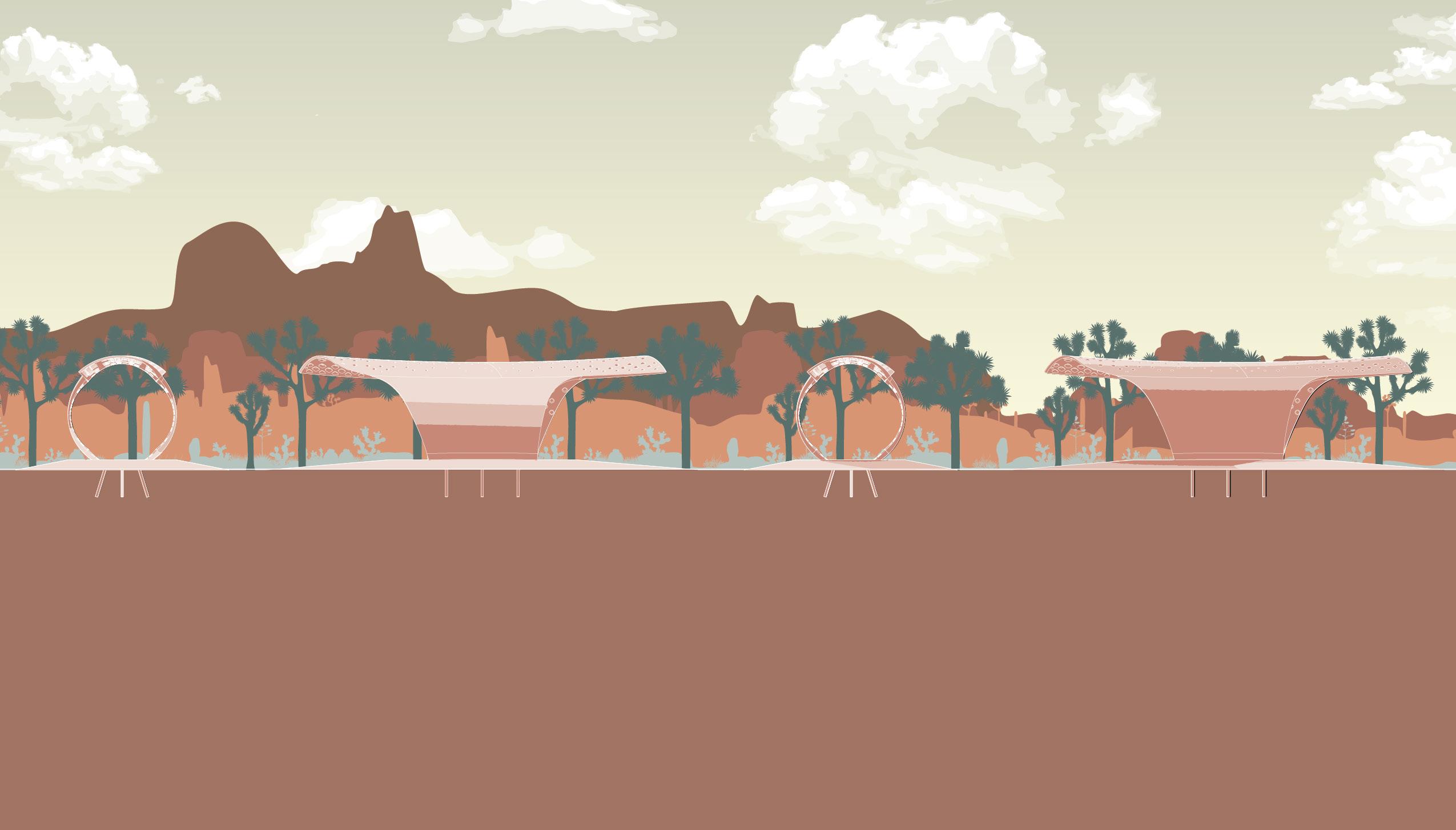
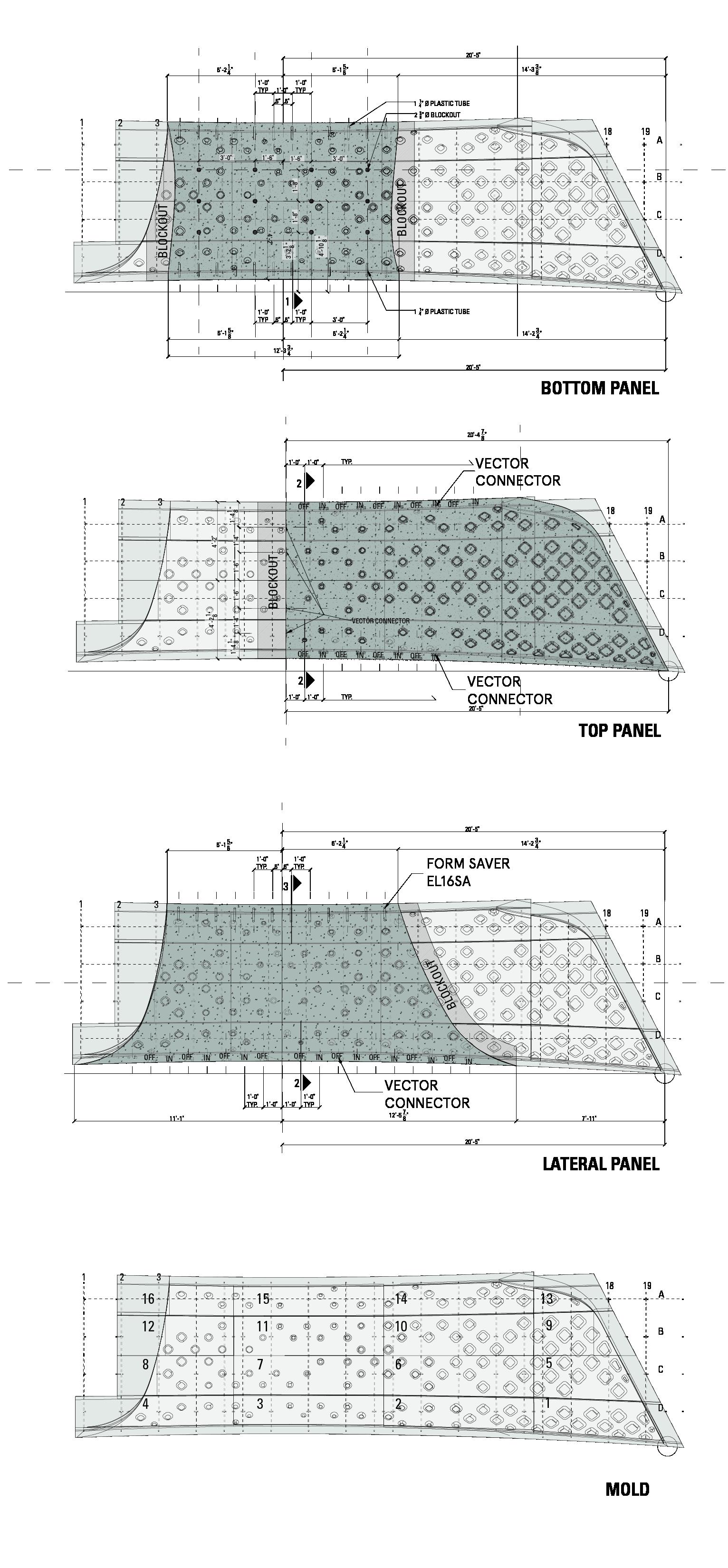
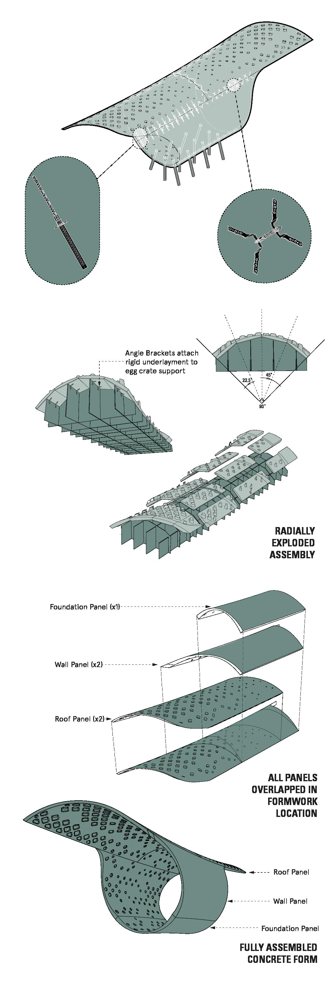
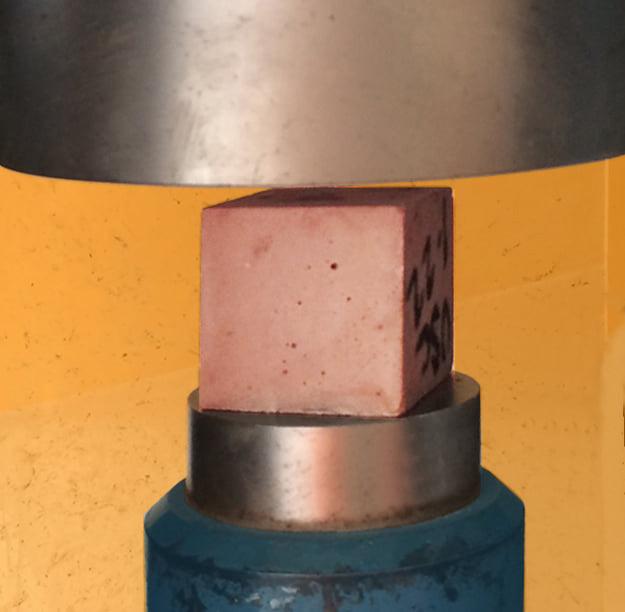
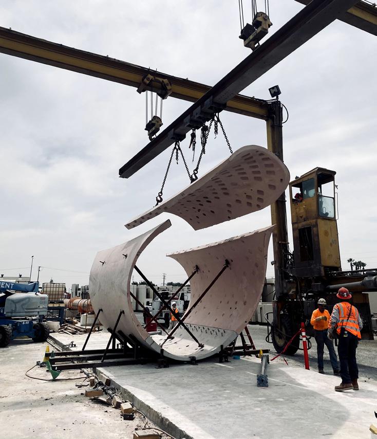
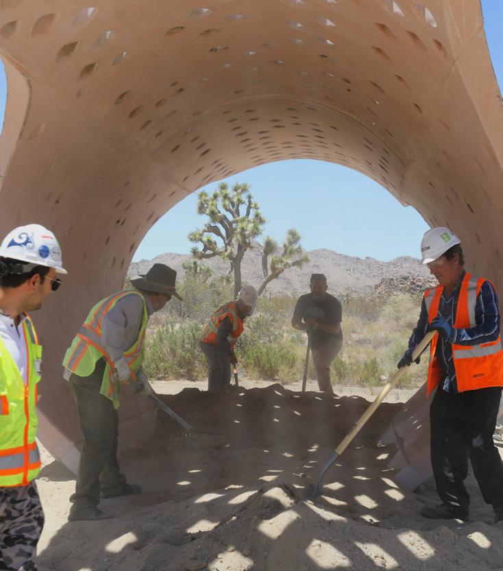
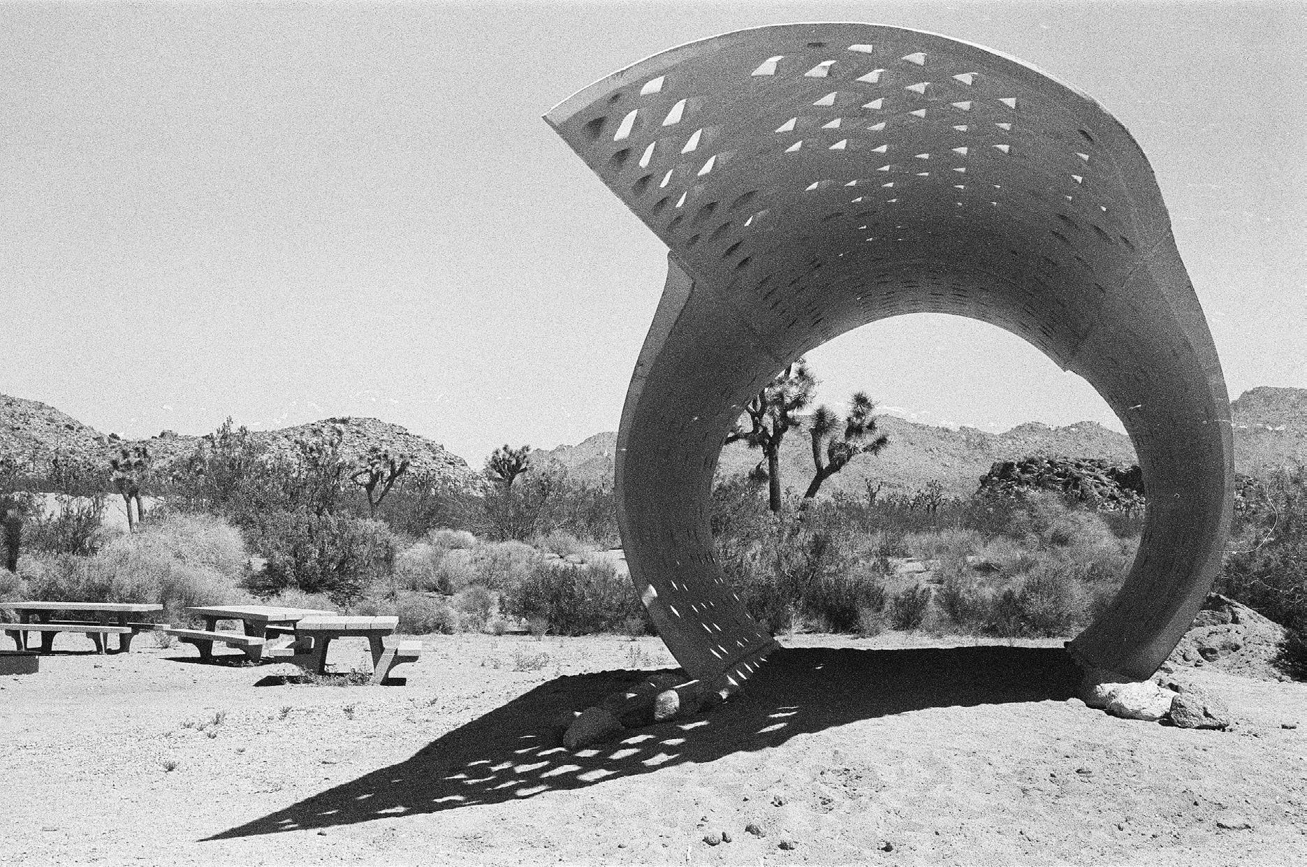
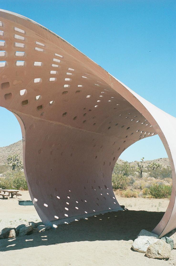
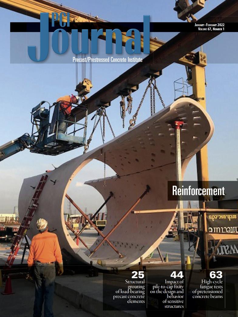
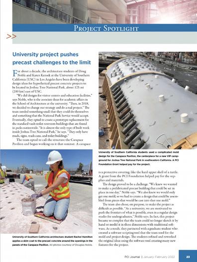
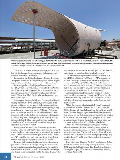
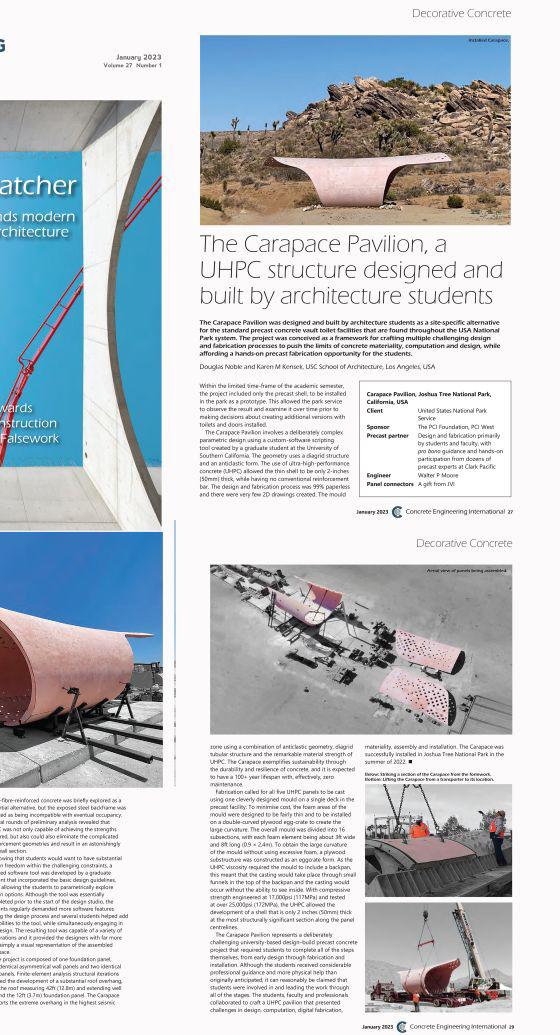
The Carapace Pavilion is a real-life, in-progress project located in Joshua Tree National Park, created as a prototype for a new bathroom design that would exist throughout the whole park. Beginning not only as a bathroom prototype, the Carapace pavilion is also a material prototype for the use of Ultra High Performance Concrete (UHPC) as a structural shell rather than just a façade treatment. The structure is an anticlastic structure with five panels all cast out of one mold. A graduate student working on this project had centered his thesis upon creating a structure as such, therefore generating a Grasshopper script that could adjust the design of the shape, whether it be turned anticlastic or synclastic, have larger or smaller openings, et cetera. The shape is essentially three circles aligned at midpoint, with the outer two having the same dimension and the inner one designed to be adjusted in size. Furthermore, the team determined the thickness of the UHPC to be a minimum of 2.5 inches while still being structural; therefore, the panels are extremely thin towards the center and thicken to about 6 inches at the edges. Each cast is attached with X-connectors by JVI. One half of the connector is cast into one panel and the other into the connecting panel, which on-site at installation time get welded together.
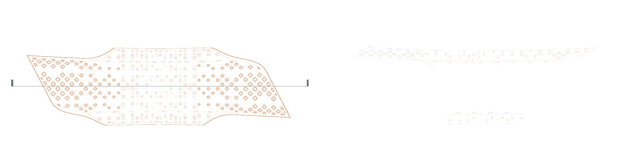
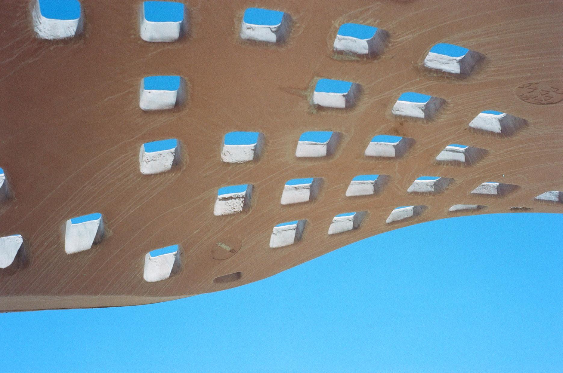
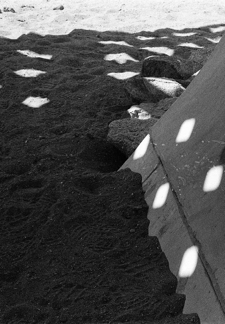
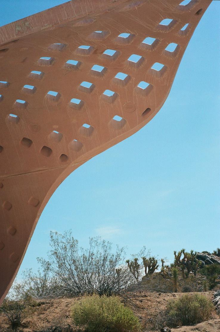
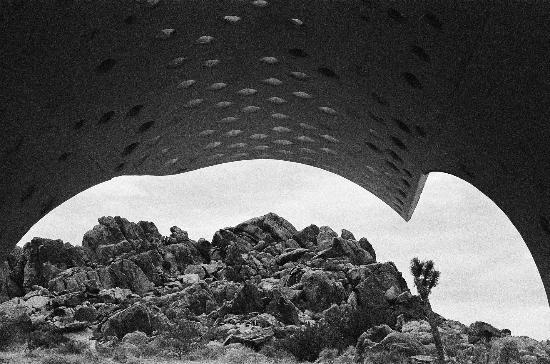
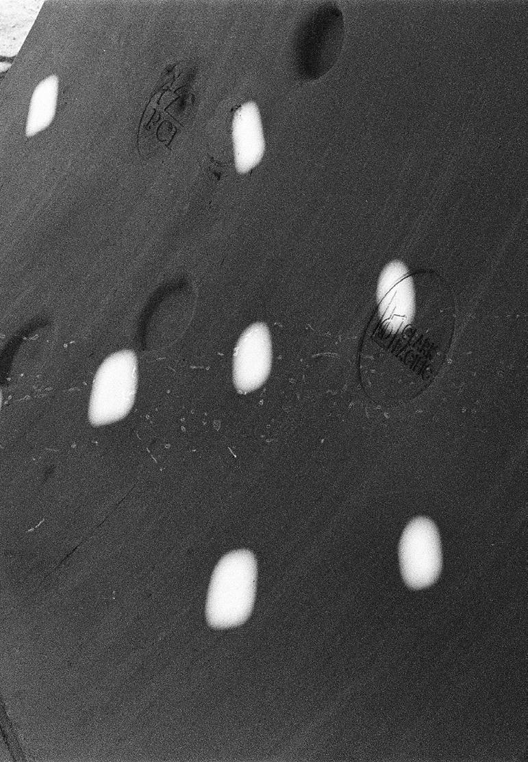
The team examined, not only the possible shape of the structure, but also its texture and apertures. Working with a group of structural engineers, it was determined that adding apertures to the wall panels could lower the structural integrity, as opposed to adding those apertures to the edge of the roof where the cantilever was would make the load lighter. We created a shape that gradated both in size and amount. Because only the roof panels have apertures, the cast had to be equipped with detachable foam block-outs for the apertures.
My part in the team was to create graphics, style, and overall look of the pavilion’s design and the drawings. I created the design of the patch that attaches to everyone’s coveralls when working, created the apertures, defined the curve of the over hang, decided the color of the UHPC, as well as created the template and graphic style for a book. Along with another student, we ran the Media Team.
https://issuu.com/kaymashiach/docs/220401_kay_mashiach_-_constructed_ histories_essay.
USC SoA
design+process

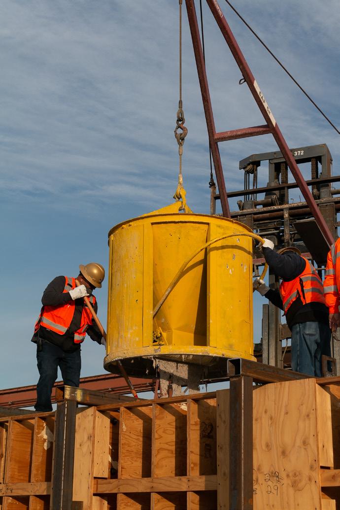
 prototyping
mold-making casting
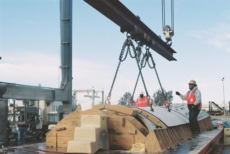
de-molding assembly installation
prototyping
mold-making casting
de-molding assembly installation


SARA California Design Awards / Student Excellence Award PCI Design Awards / Best Custom Solution PCI Design Awards / AllPrecast Solution AIA LA Design Awards / Installation Typology Design Citation Awards 2023 2022 2022 2021 reception
Countless individuals, companies, and disciplines sought to provide collaborative efforts for the Carapace Pavilion, as to impart their knowledge but even more so to capitalize on the experimentation engagement. The Carapace provided an academic outlook on architecture which deals in innovation and deviation of the typical procedures recorded in the industry. However, the project also situated itself on a deliberate platform intended to explore the ability of implementing rigorous and complex systems in a real-world practice.
Acknowledgements must be given to everyone involved, including Clark Pacific, JVI, Lafarge Holcim, Clark Construction, Cresset, PCI West, PCI Foundation, Walter P. Moore, and countless student and faculty volunteers. The Carapace is an award-winning pavilion and has been published in quite a few publications for its innovation.
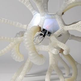
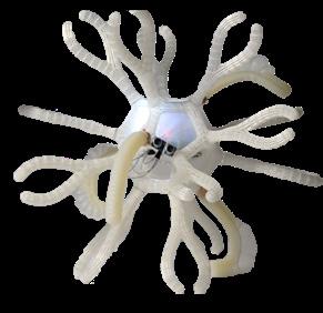
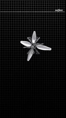
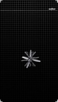
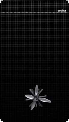
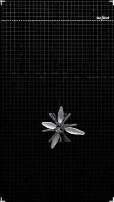
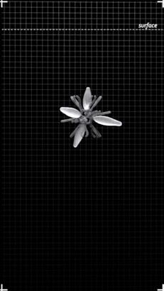
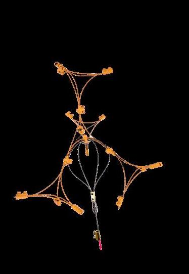
society nano
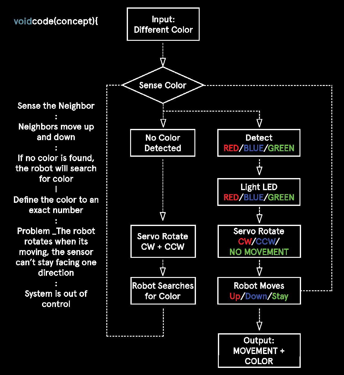
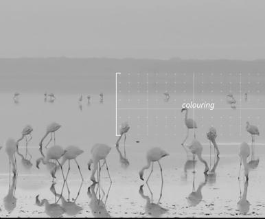
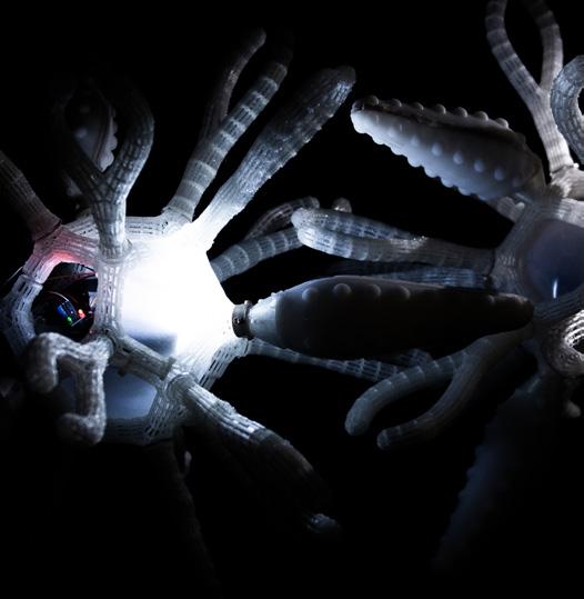
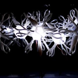
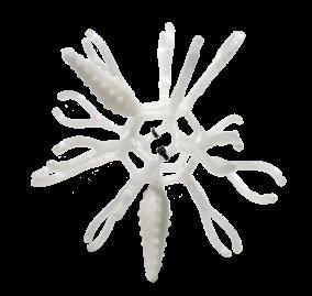
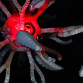
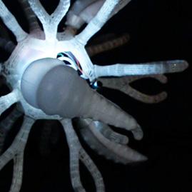
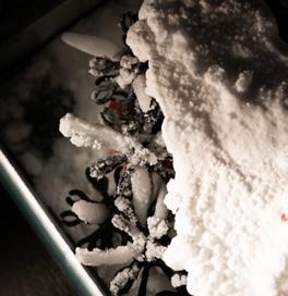
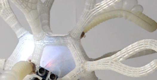
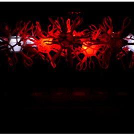
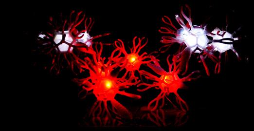
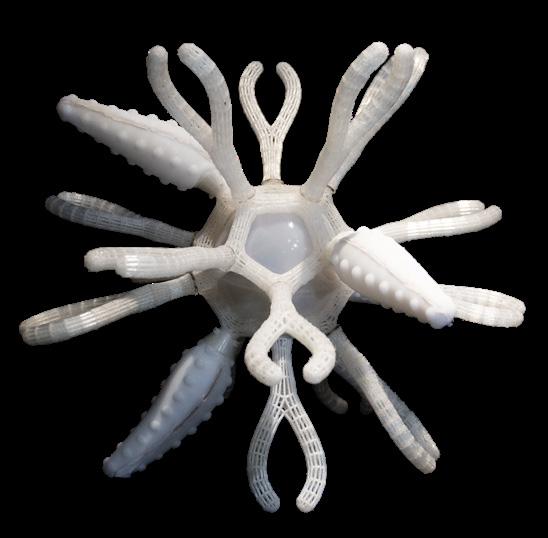
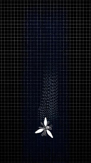
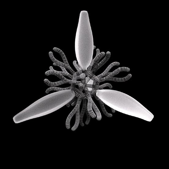
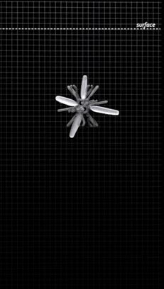
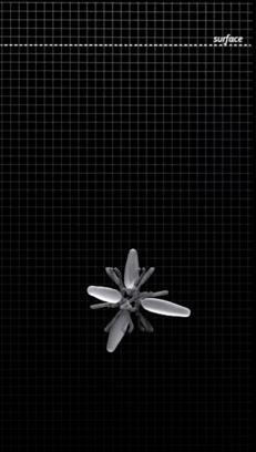
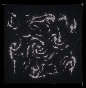
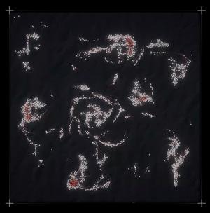
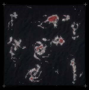
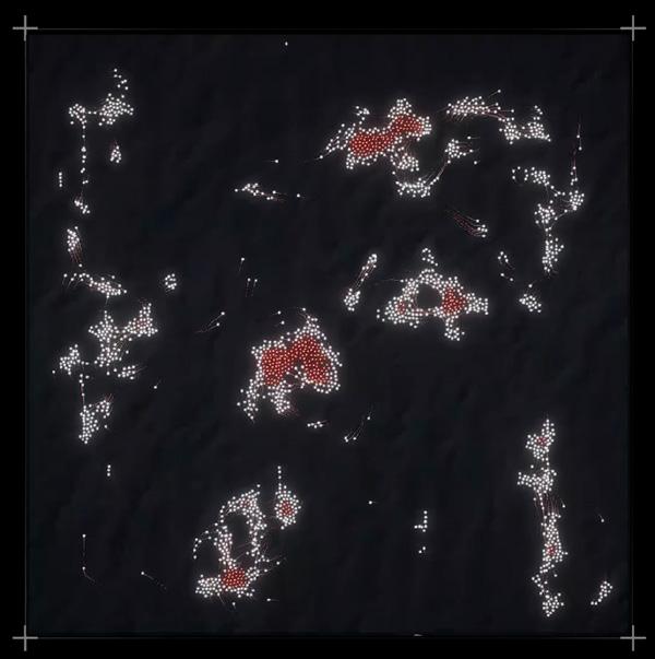
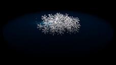
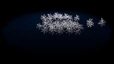
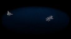
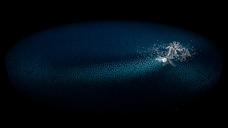
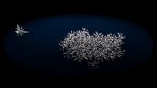
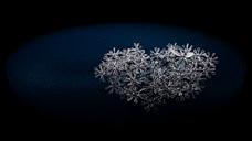
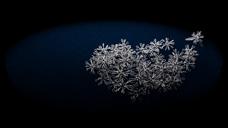
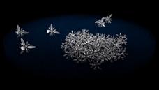
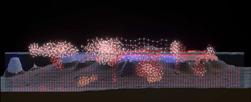
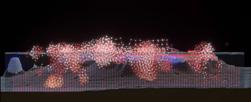
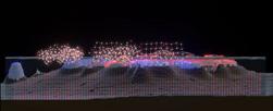
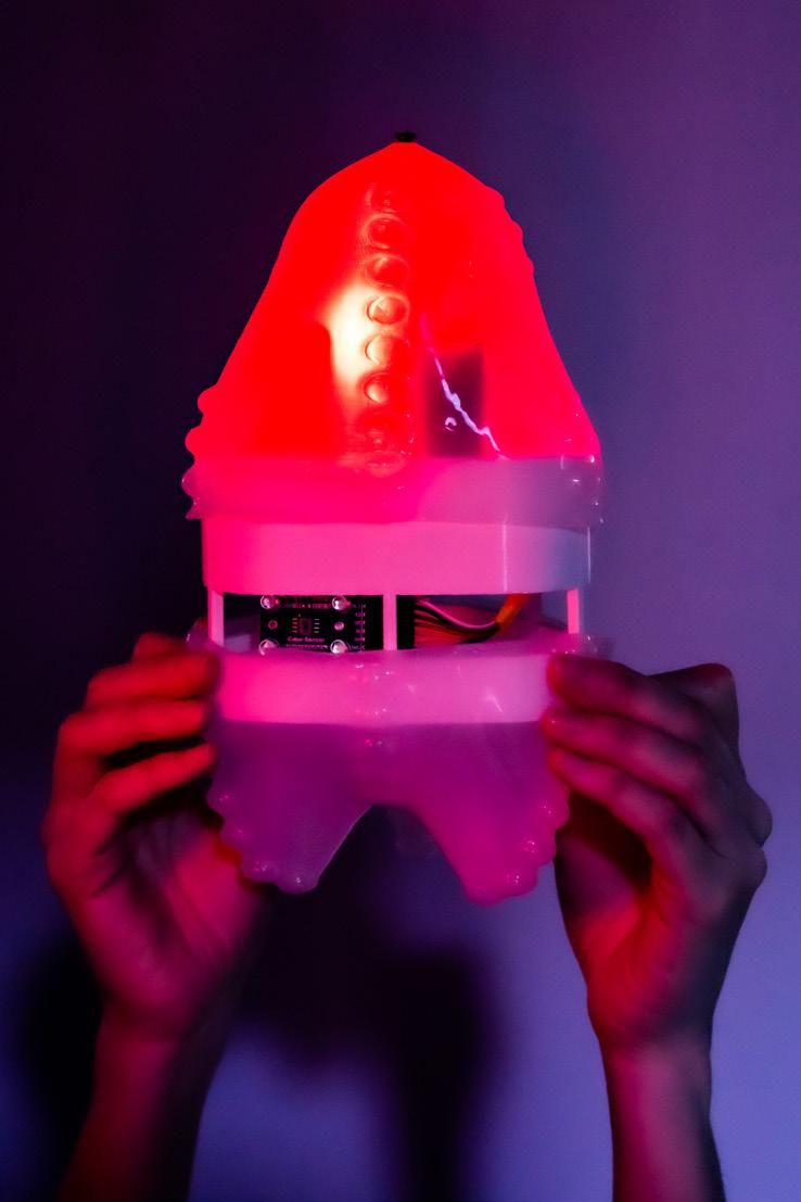
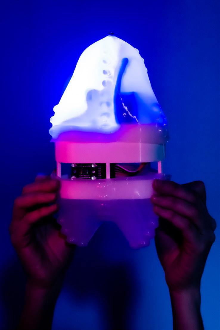
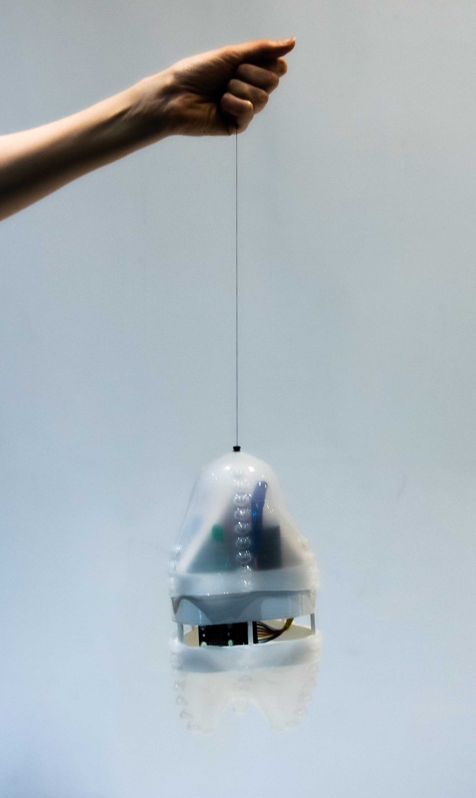
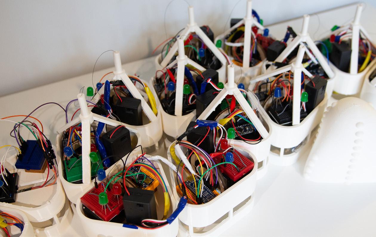
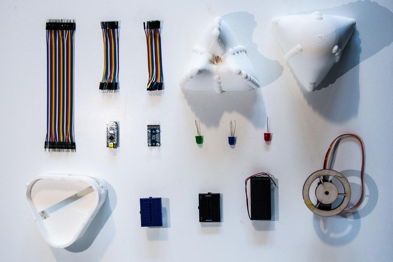
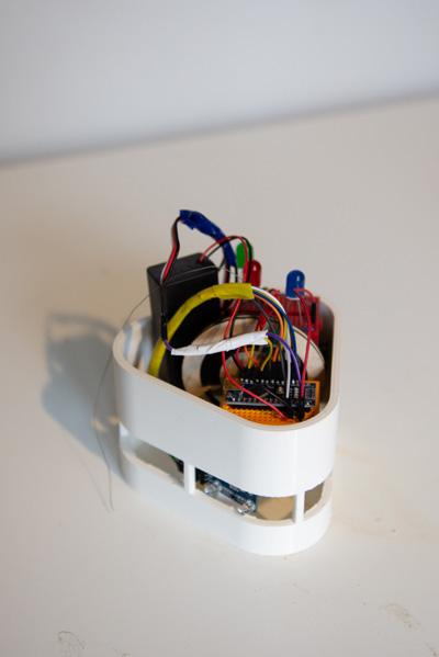
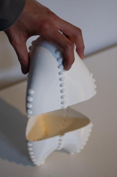
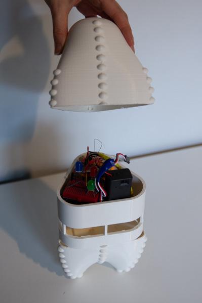
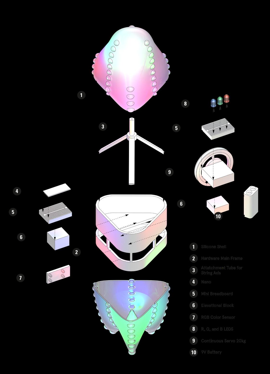
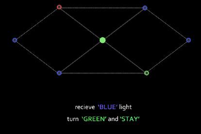
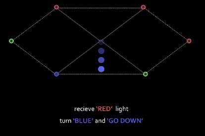
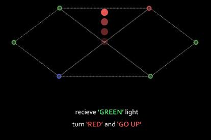
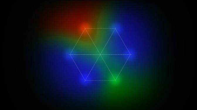
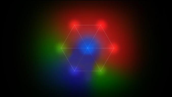
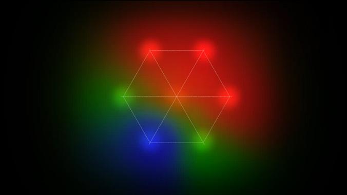
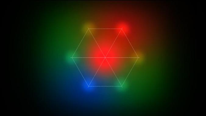
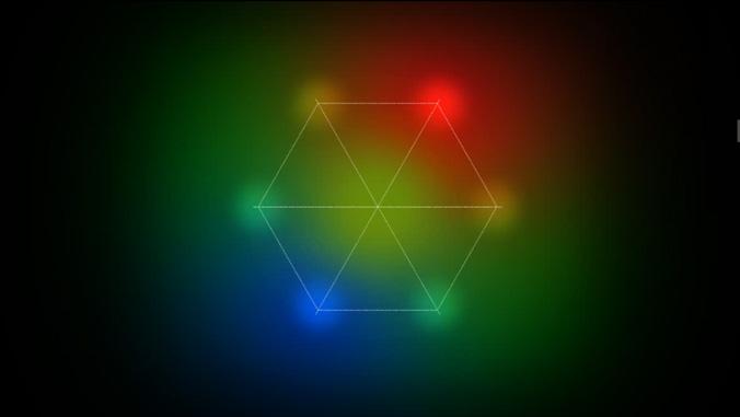
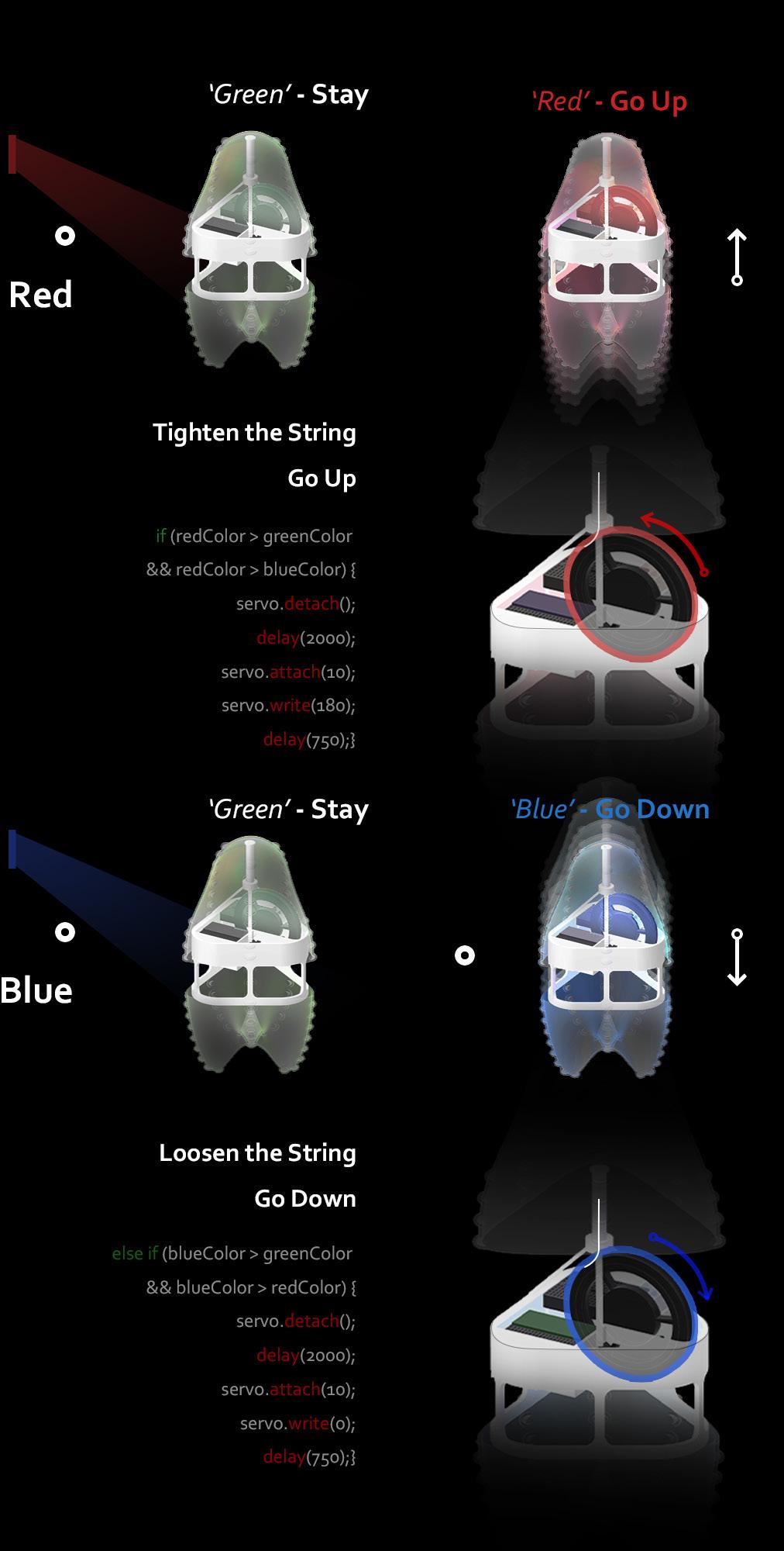
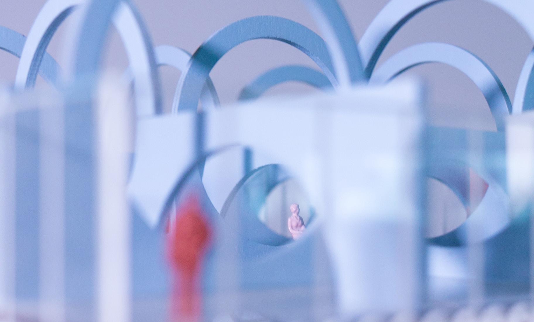
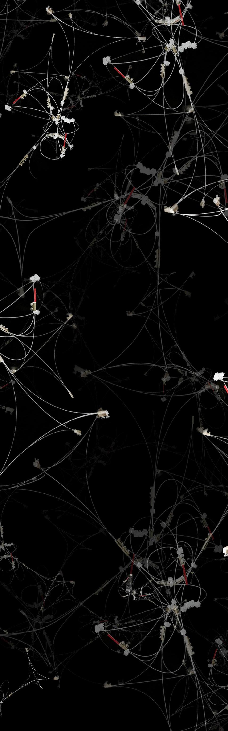
Completed with a group for an AA DRL workshop focused on Arduino and coding, we were given the options to create robots with Machine-Human, Machine-Environment, and MachineMachine interaction. We focused on the last, seeking inspiration from bio-luminescence, underwater creatures, and air balloons. Simplicity in concept was the key to complexity in this case, so we decided to employ the use of color sensing, specifically of red, green, and blue. Initially the goal was a flying robot, but with the time-frame of four weeks, it was more realistic to create the illusion of floating robots. We created a pulley system, with fishing wire attached to a continuous rotational servo. The robots were each comprised of a color sensor, red, green, and blue LEDs, a servo, battery, Arduino nanos, and breadboards. By setting up a higher population of robots, in our case, 18, we were able to identify reactions from a simple rule-set engaging in the emergence of patterns. At first, the robots detected a color and then emitted the same color of detection, but it resulted the eventual entropy of all robots encountering a single state (a single color). The system would then stop. We then turned to the more complex rule-set in which a single color detected converts to a different color (not that of which is detected). The result was a continuous system, with each moment having an overall idiosyncratic state. The complexity brought out from this rule-set resulted in an unpredictable organization.

AA DRL
agent
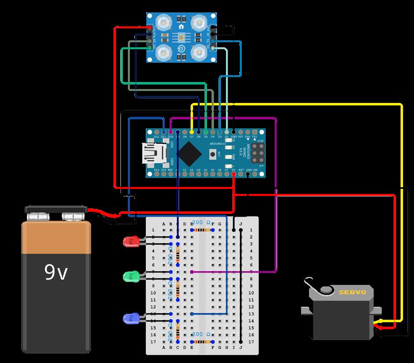

1 2 3 4 5 6 7 8 9 10 11 12 13 14 15 16 17 18 19 20 21 22 23 24 25 26 27 28 29 30 31 32 33 34 35 36 37 38 39 40 41 42 43 44 45 46 47 48 49 50 51 52 53 54 55 56 57 58 59 60 61 62 63 64 65 66 67 68 69 70 71 72 73 74 75 76 77 78 79 80 81 82 83 84 85 86 87 88 89 90 91 92 93 94 95 96 97 98 99 100 101 102 103 104 105 106 107 108 109 110 111 112 113 114 115 116 117 118 119 120 121 122 123 124 125 126 127 128 129 130 131 132 133 134 135 136 137 138 139 #include<Servo h> Servo servo; int servoPin = 7; #define S0 2 #define S1 3 #define S2 4 #define S3 5 #define sensorOut 6 #define redLED 12 //analog~ #define greenLED 9 //analog~ #define blueLED 8 //analog~ int redMin = 65; int redMax = 719; int greenMin = 94; int greenMax = 1332; int blueMin = 106; int blueMax = 1594; int redPW = 0; int greenPW = 0; int bluePW = 0; int redValue; int greenValue; int blueValue; void setup() { pinMode(S0 OUTPUT); pinMode(S1, OUTPUT); pinMode(S2, OUTPUT); pinMode(S3, OUTPUT); pinMode(redLED OUTPUT); pinMode(greenLED OUTPUT); pinMode(blueLED, OUTPUT); servo attach(servoPin); pinMode(sensorOut INPUT); digitalWrite(S0, HIGH); digitalWrite(S1, LOW); Serial begin(9600); } void loop() { calibration(); showColor(); servoRotate(); } void calibration () { redPW = getRedPW(); redValue = map(redPW, redMin, redMax, 255, 0); delay(400); greenPW = getGreenPW(); greenValue = map(greenPW greenMin greenMax 255 0); delay(400); bluePW = getBluePW(); blueValue = map(bluePW, blueMin, blueMax, 255, 0); delay(400); Serial print(“Red = “); Serial print(redValue); Serial print(“ - Green = “); Serial print(greenValue); Serial print(“ - Blue = “); Serial println(blueValue); } int getRedPW() { digitalWrite(S2, LOW); digitalWrite(S3, LOW); int PW; PW = pulseIn(sensorOut, LOW); return PW; } int getGreenPW() { digitalWrite(S2, HIGH); digitalWrite(S3 HIGH); int PW; PW = pulseIn(sensorOut, LOW); return PW; } int getBluePW() { digitalWrite(S2, LOW); digitalWrite(S3, HIGH); int PW; PW = pulseIn(sensorOut LOW); return PW; } void showColor() { if (redValue > greenValue && redValue > blueValue) { digitalWrite(redLED LOW); digitalWrite(greenLED, LOW); digitalWrite(blueLED, HIGH); } else if (greenValue > redValue && greenValue > blueValue) { digitalWrite(redLED, HIGH); digitalWrite(greenLED, LOW); digitalWrite(blueLED, LOW); } else if (blueValue > redValue && blueValue > greenValue) { digitalWrite(redLED, LOW); digitalWrite(greenLED, HIGH); digitalWrite(blueLED, LOW); } } void servoRotate() { if (redValue > greenValue && redValue > blueValue) { delay(100); servo attach(7); servo write(98); delay(100); } else if (blueValue > greenValue && blueValue > redValue) { servo attach(7); servo write(91); delay(200); } else if (greenValue > redValue && greenValue > blueValue) { delay(500); servo attach(7); servo write(65); delay(200); } }
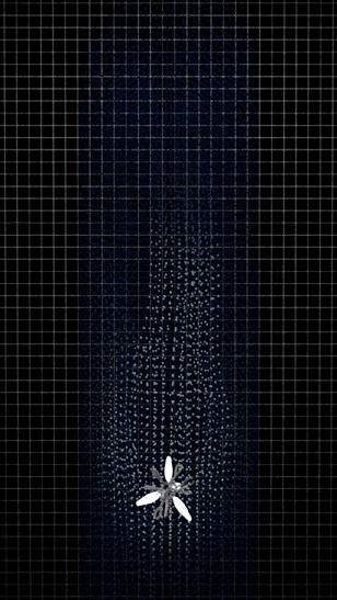
site+application
if ( greenValue > redValue && greenValue > blueValue ) {
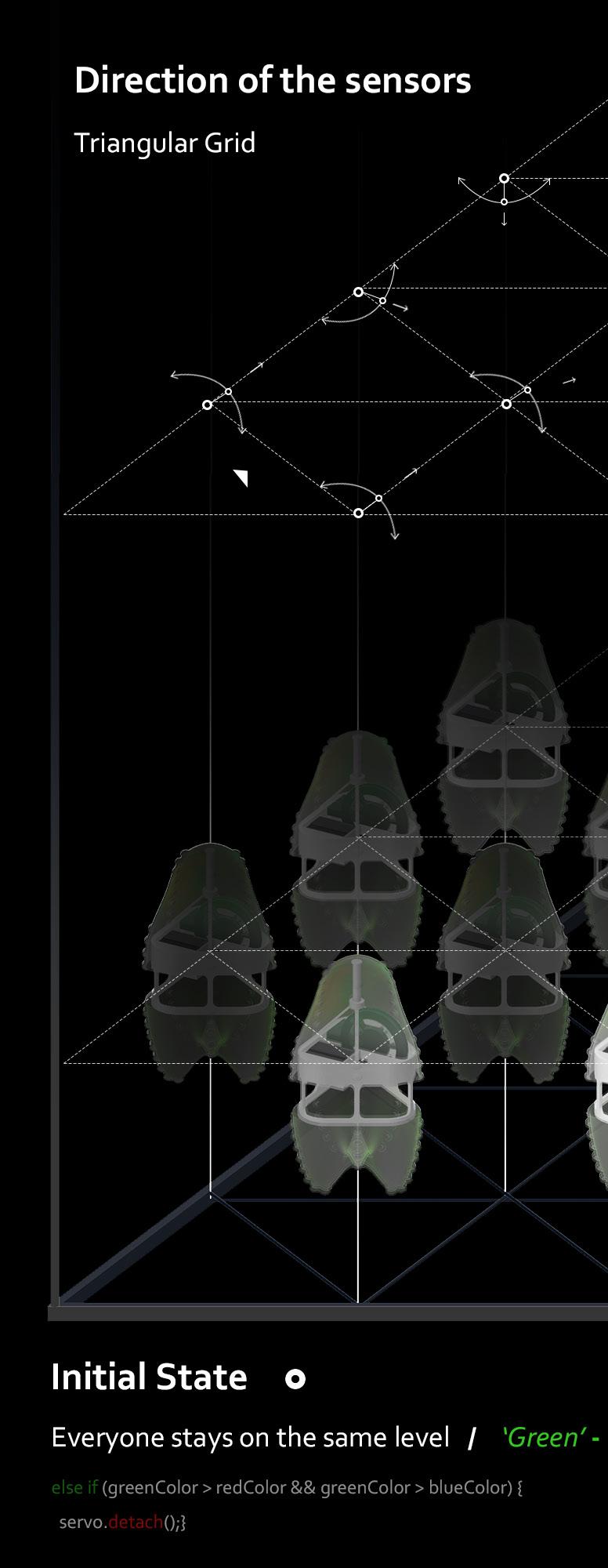
Direction of the Sensors
Triangular Grid
if ( blueValue > redValue && blueValue > greenValue ) {


if ( greenValue > redValue && greenValue > blueValue ) {
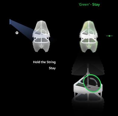
Initial State Everyone stays on the same level / else if (greenColor > redColor && greenColor > blueColor) { servo.detach();}

‘Green’ _
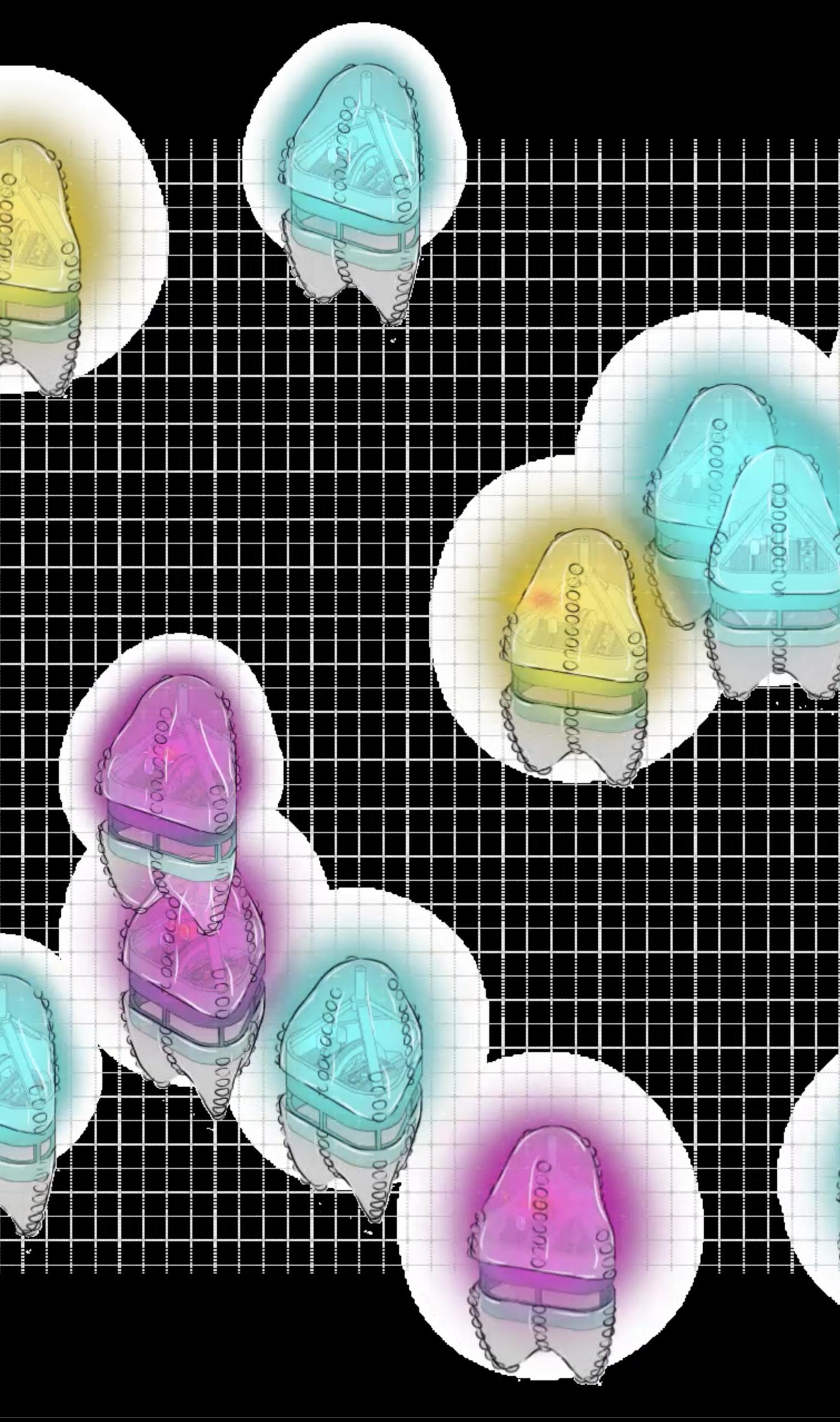
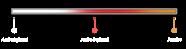
Read color in the center R:50 G:200 B:180 color map ‘red‘ React to certain color in the center color map ‘blue’ R:174 G:70 B:20 Read color in the center React to certain color in the center color map ‘green’ R:50 G:110 B:180 Read color in the center React to certain color in the center
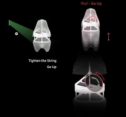
Tighten the String Go Up
if (redColor > greenColor && redColor > blueColor) { servo.detach(); delay(2000); servo.attach(10); servo.write(180); delay(750);}
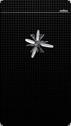
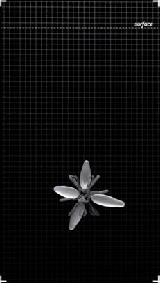
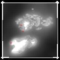
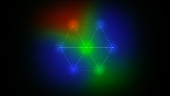
Under the new rules, all individuals come together to form a NANO-society. We cannot predict how they will move because they respond consciously in a complex color field, forming a self-organizing system.
When the robot sits in a high-population collective, its sensors read local RGB data instead of individual colors. Neighbors present many different colors, so the sensor is set up to read composite color and judges the relationship of the RGB data to determine how it should react.
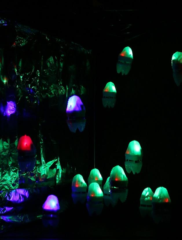
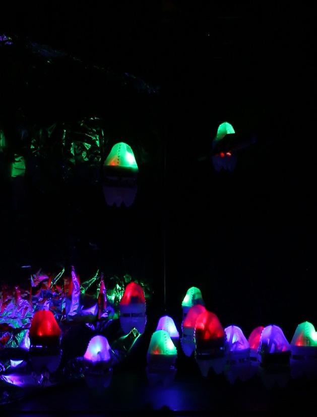
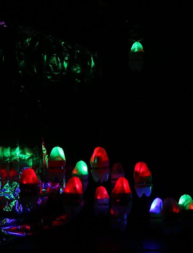
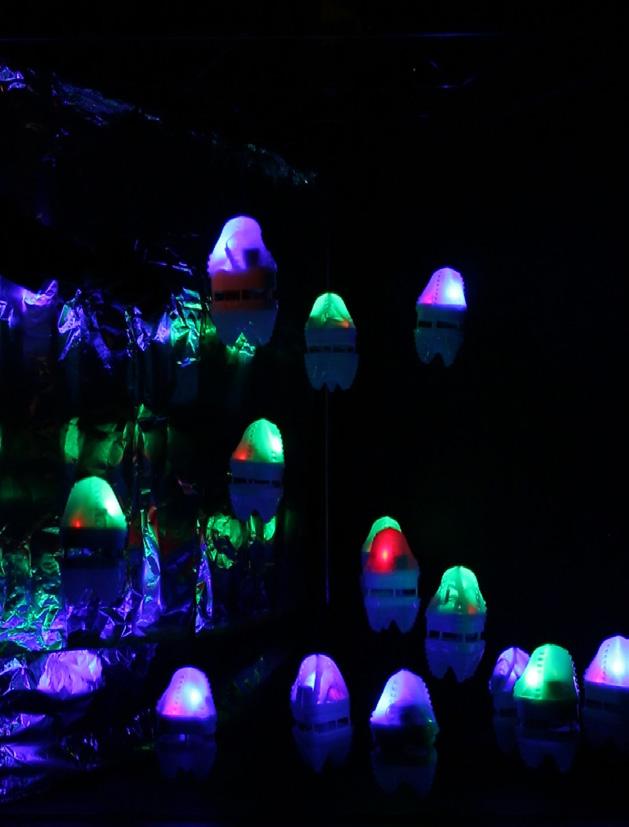
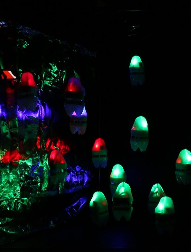
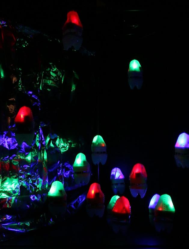
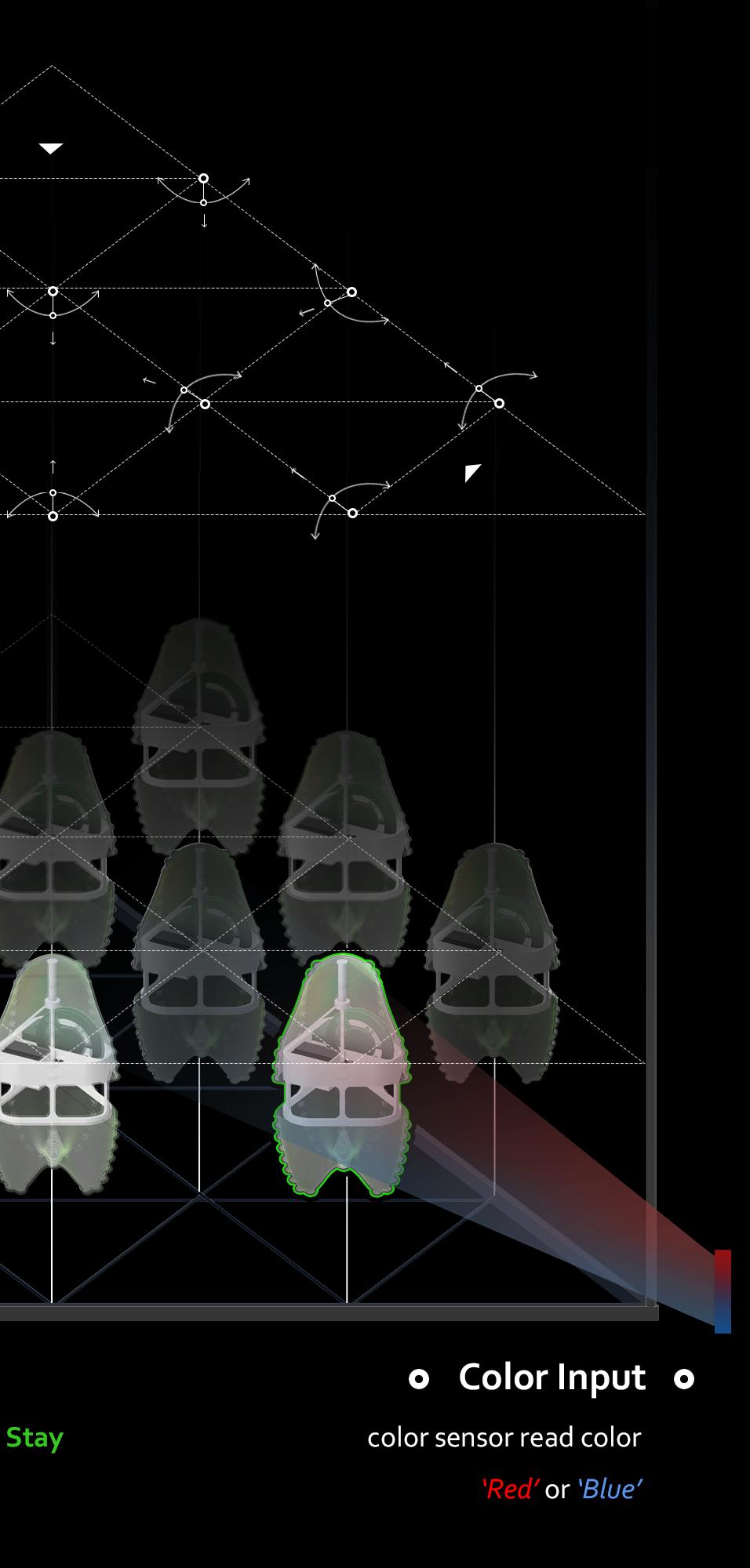
Tinfoil was employed to close the edges of the frame, reflecting light back into the area, and allowing the sensor to read more accurate color data.
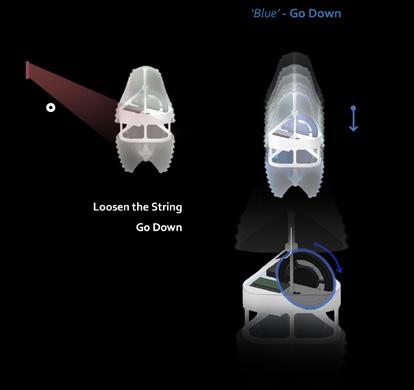
Tighten the String Go Up
else if (blueColor > greenColor && blueColor > blueColor) { servo.detach(); delay(2000); servo.attach(10); servo.write(0); delay(750);}
Color Input Red Blue color sensor read color
Stay
‘Green’ _ Stay ‘Red’
‘Blue’ _ Go Down ‘Red’ or ‘Blue’
‘Green’ _ Stay
_ Go Up
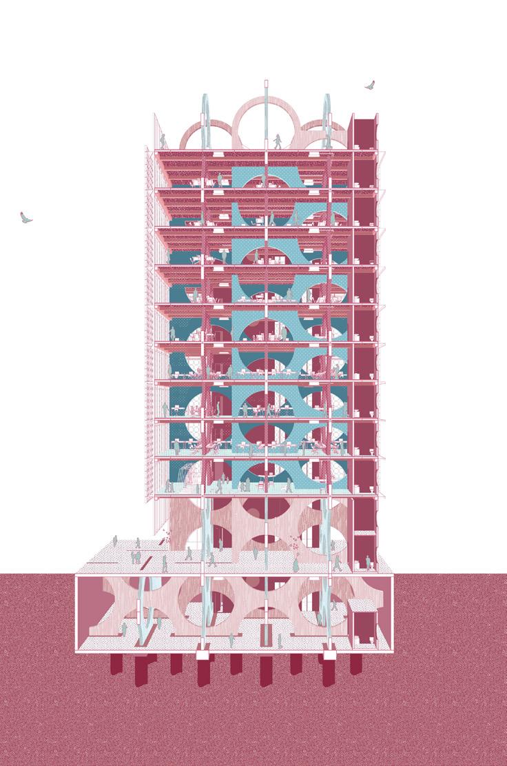
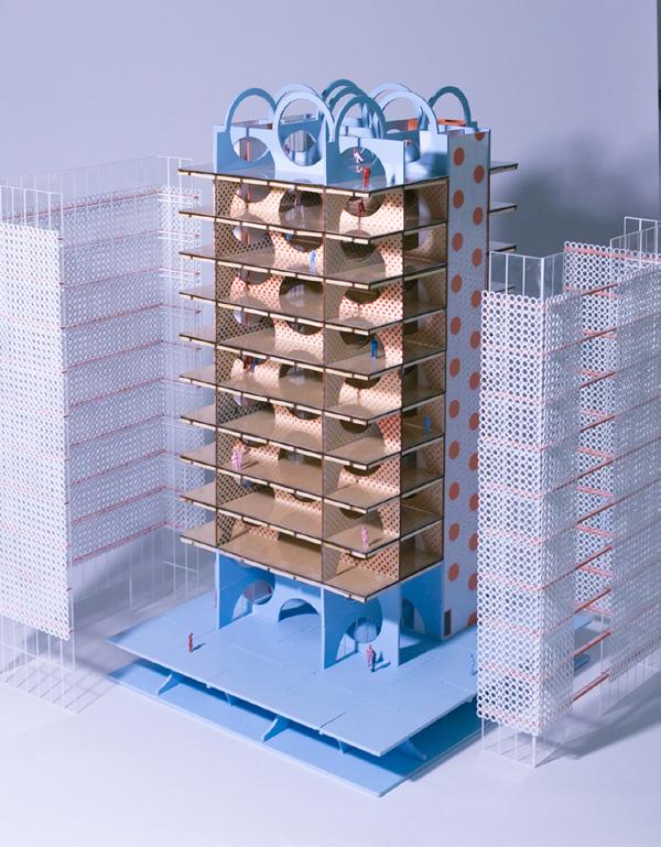
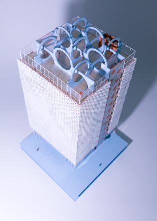
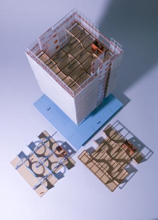
timber tower USC SoA
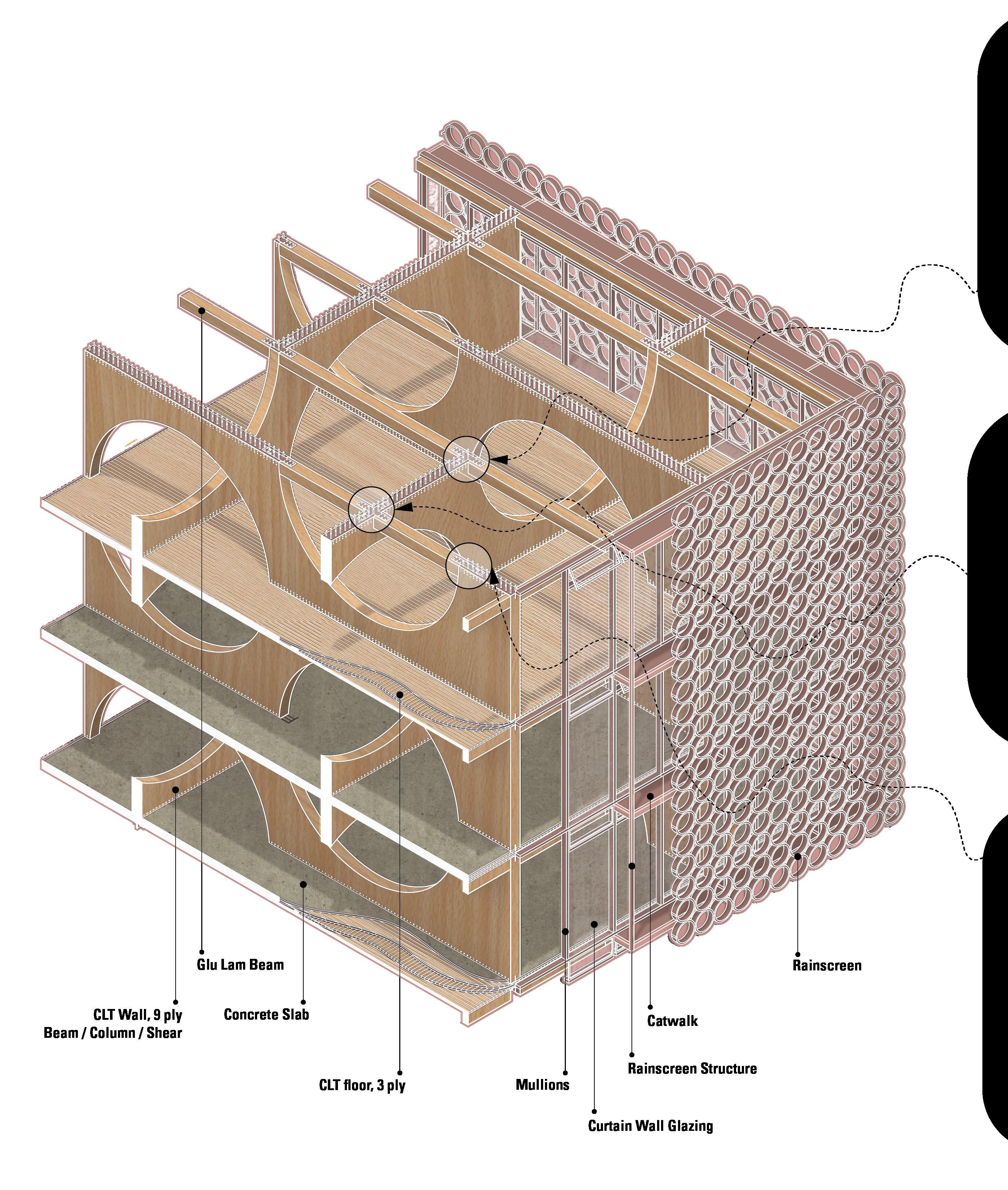
The Timber Tower is a comprehensive studio project which prompts the design of an office space using cross-laminated timber (CLT) construction. The project received the Innovation Award, determined by reviewing before a Super Jury.
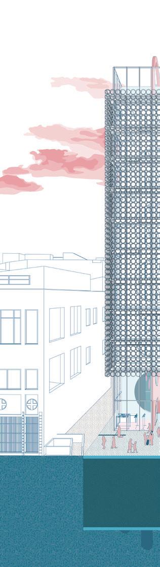
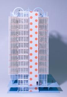
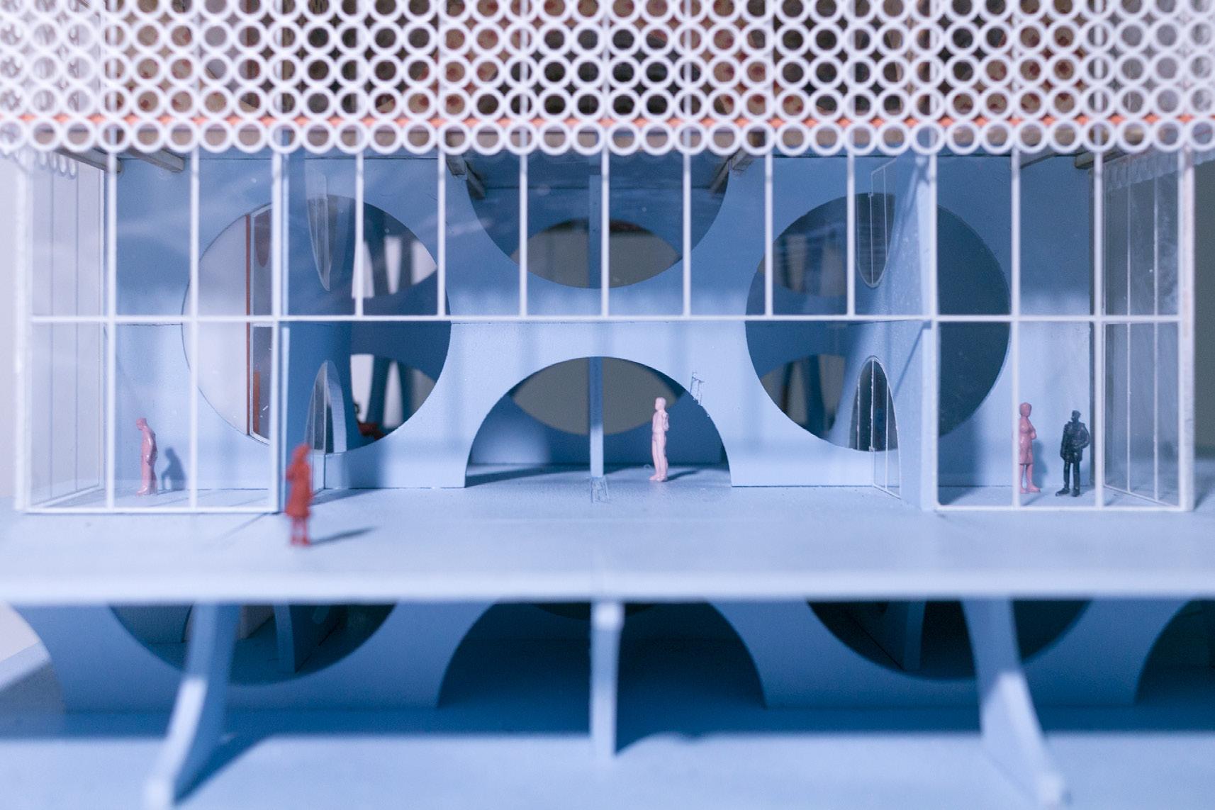
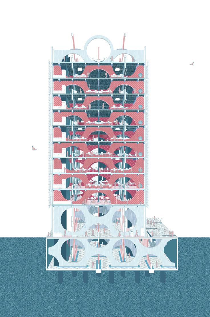
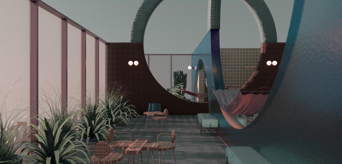
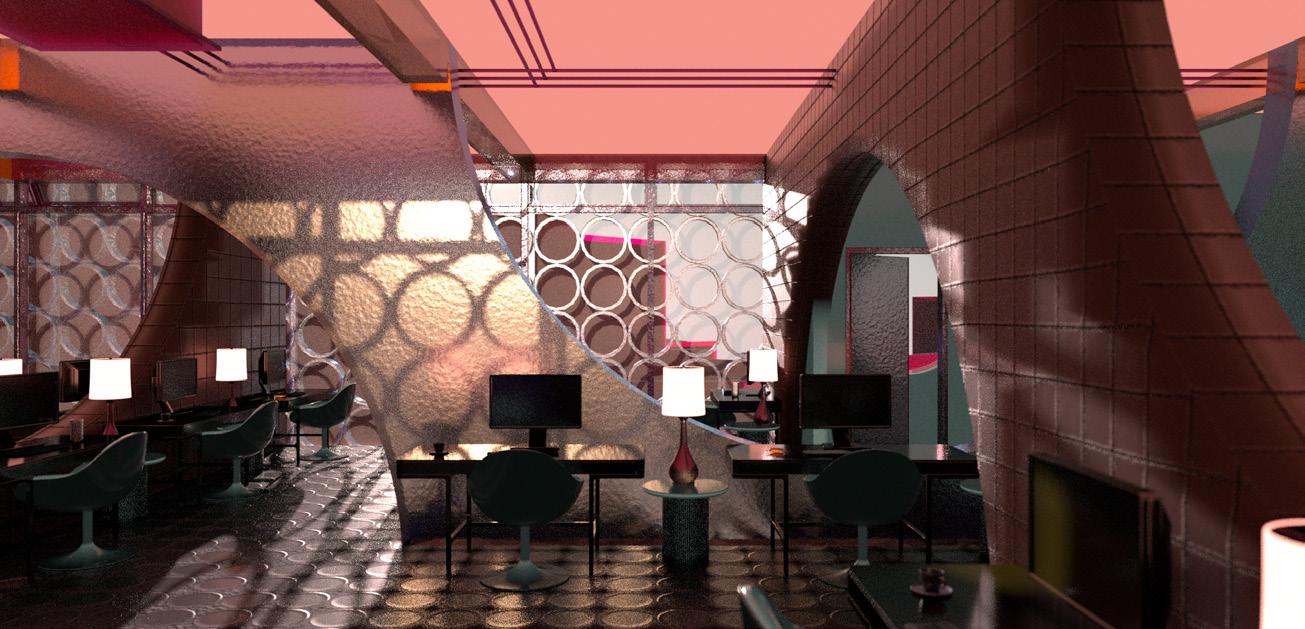
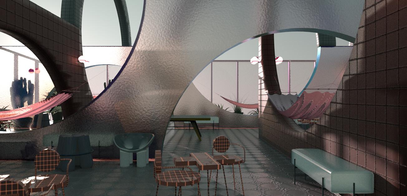
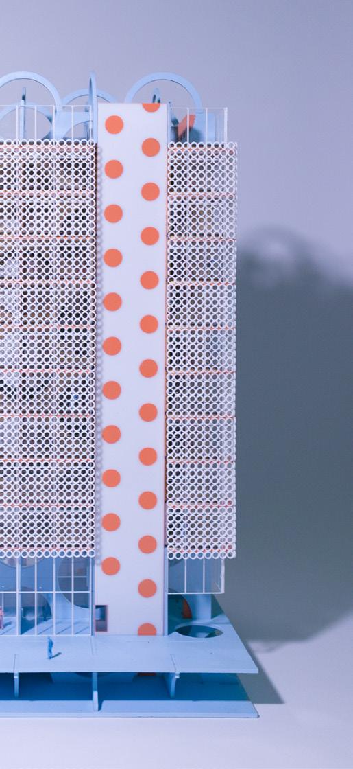
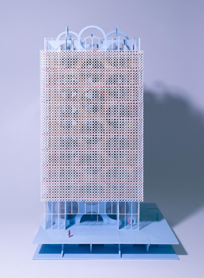
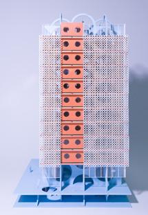
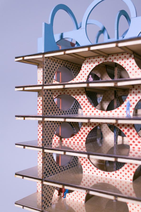
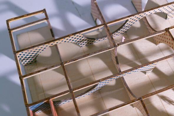
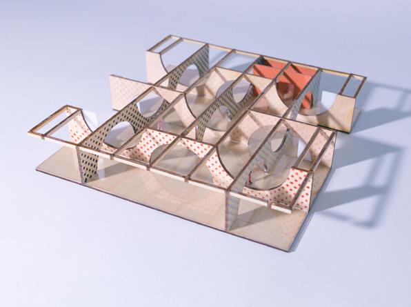
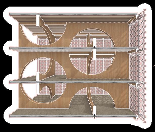
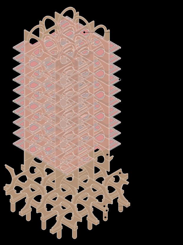
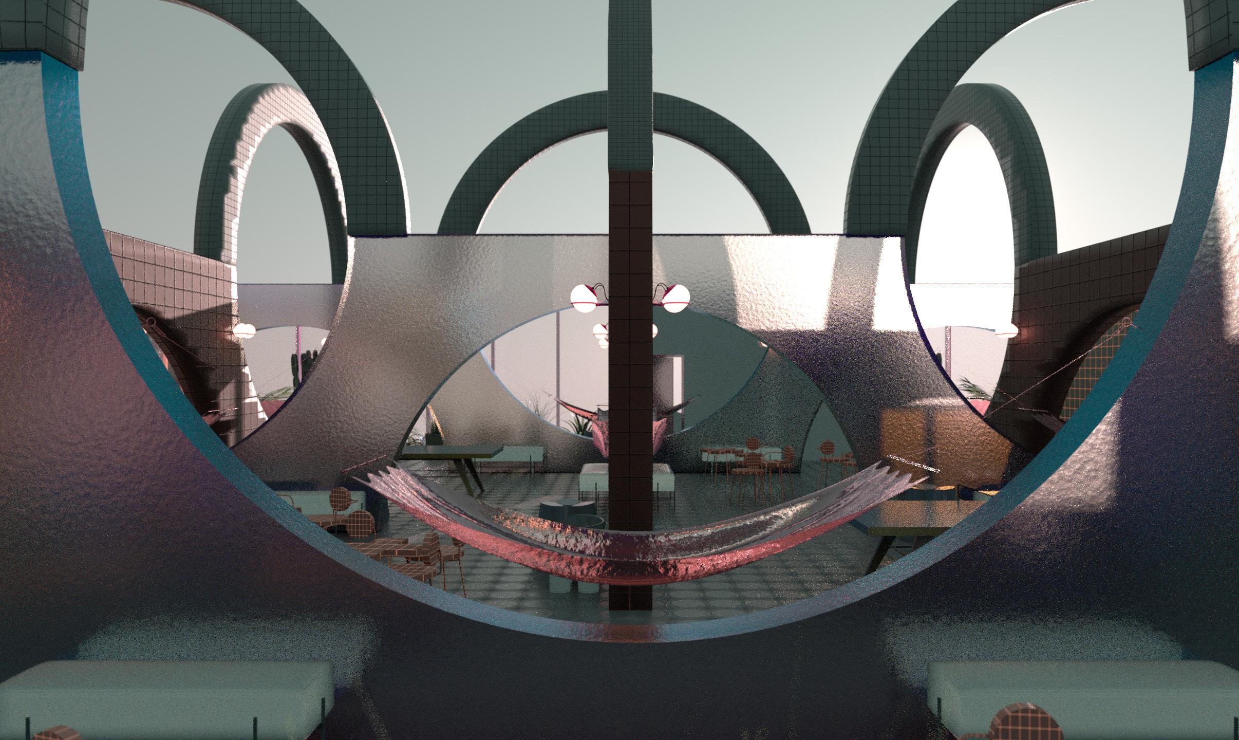
The structural design of this project centers itself around the idea of the “penetrable shear wall”. In prescribed circumstances, the shear wall must be an uninterrupted wall from ground to roof to perform as a structurally sound building. However, by utilizing circular holes throughout the entire wall, it allows the shear wall to be inhabited safely. The use of the circle provides sufficient load transfer through the wall, acting both gravitationally and laterally.
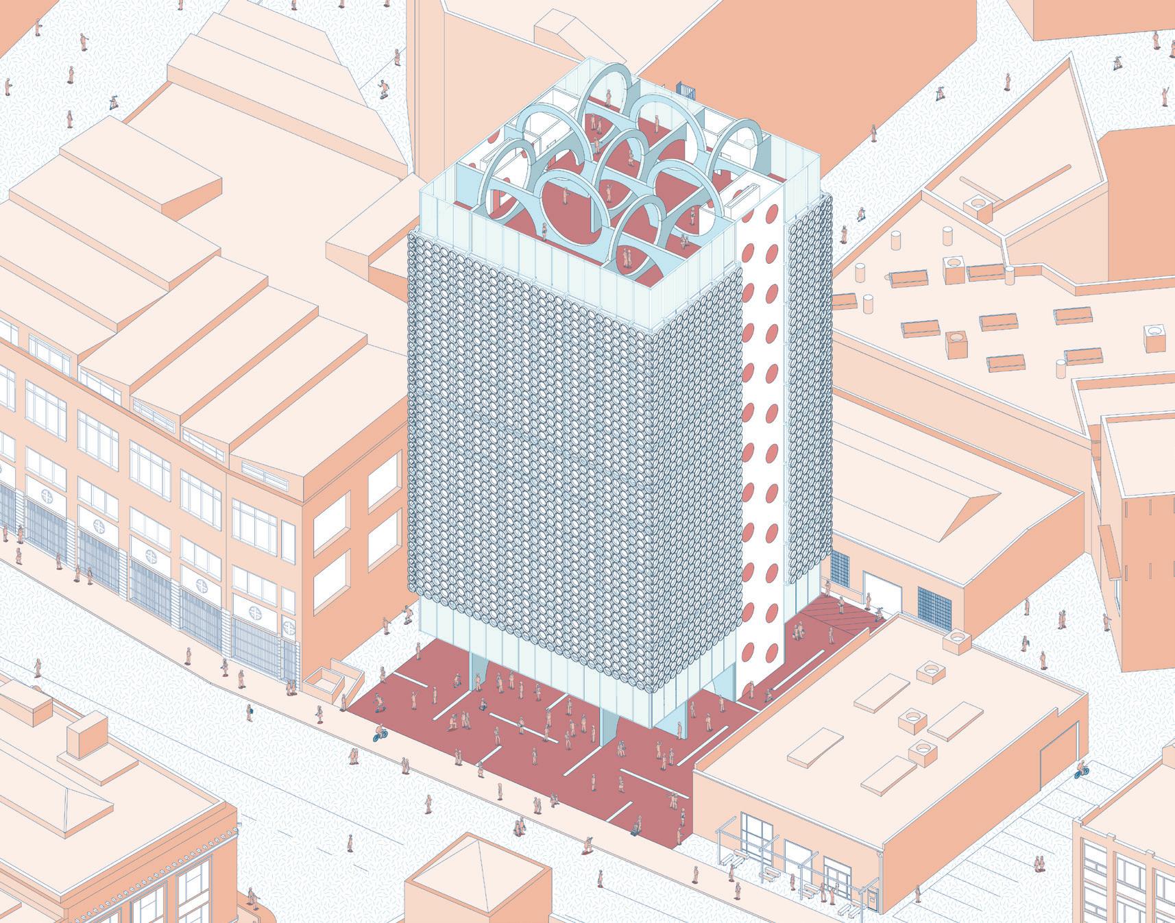
The structural grid used caters to the maximum size of a CLT floor panel. In each direction sit three walls, sequentially alternating the organization of the circles so that one circle was not in line with the circle on the following wall. By alternating the walls, it creates a smaller grid size, with the perception of uninterrupted spaces as a result of the openings. Because the structure of the building is essentially a series of CLT shear walls, the cores of the building are not a necessary part of the structure.
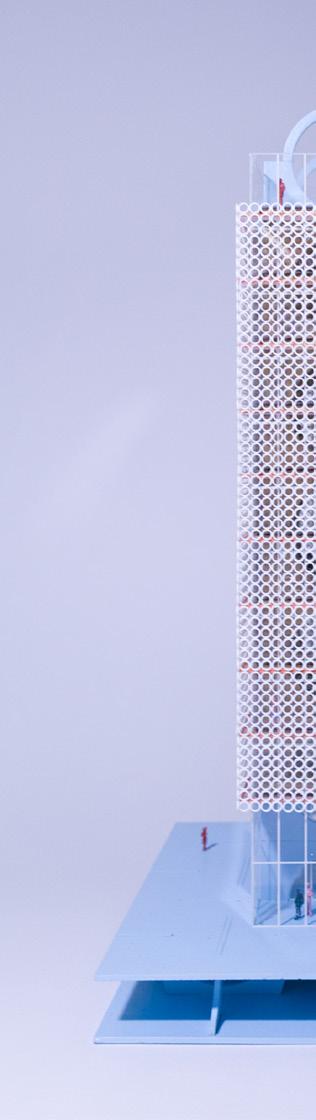
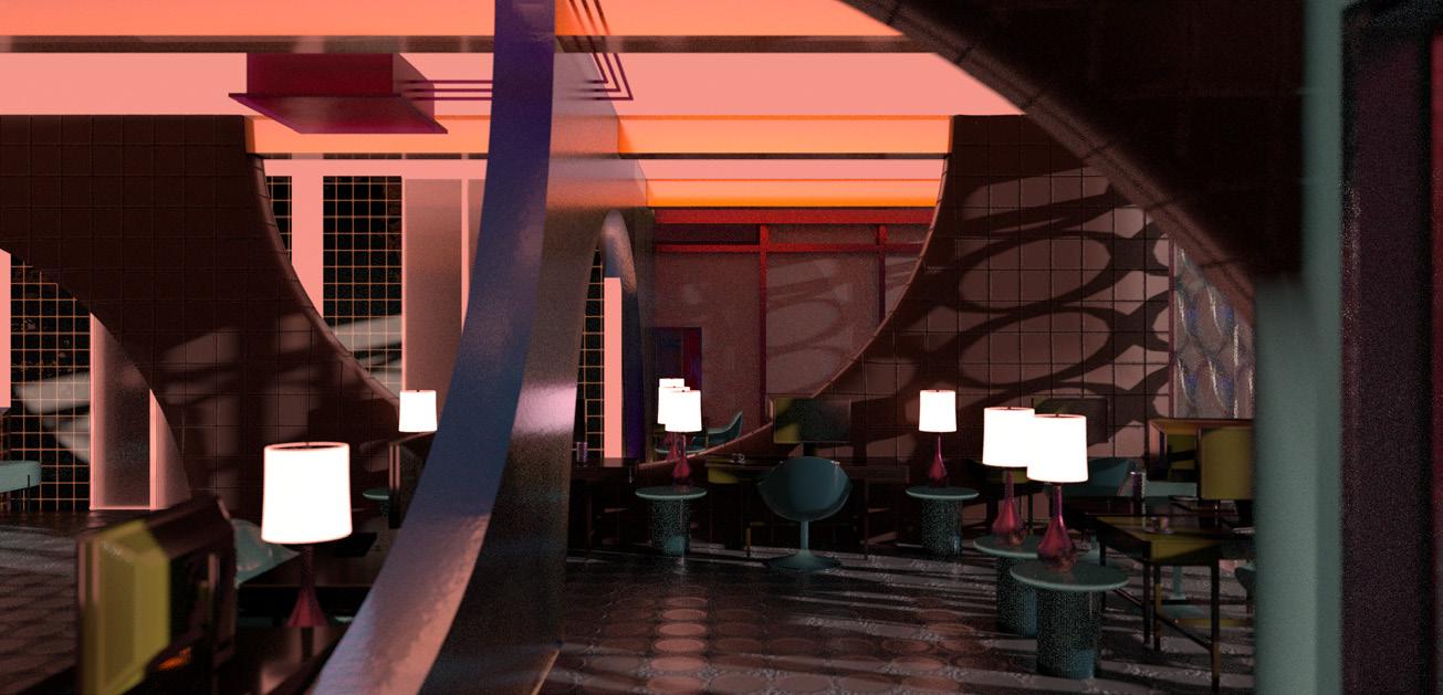
The use of the circles within the shear walls provide continuous and open circulation throughout the building, while simultaneously providing opportunities for pockets and privacy. Throughout this project, it was necessary to create a new take on the open office floor plan. Rather than placing a grid of columns, the interest lay in how the structure can inform spatial conditions while not be obstructive to the environment.
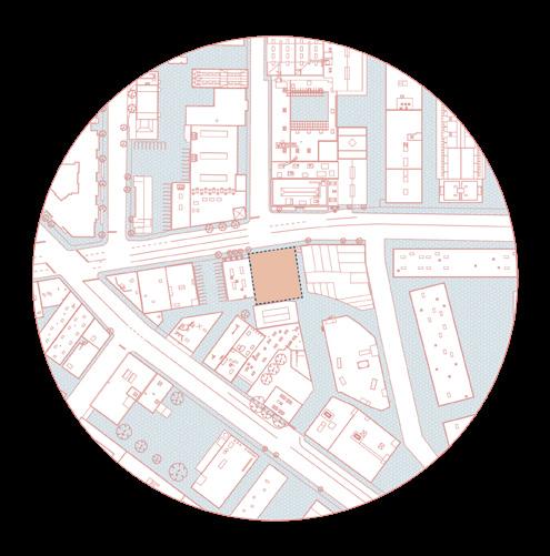
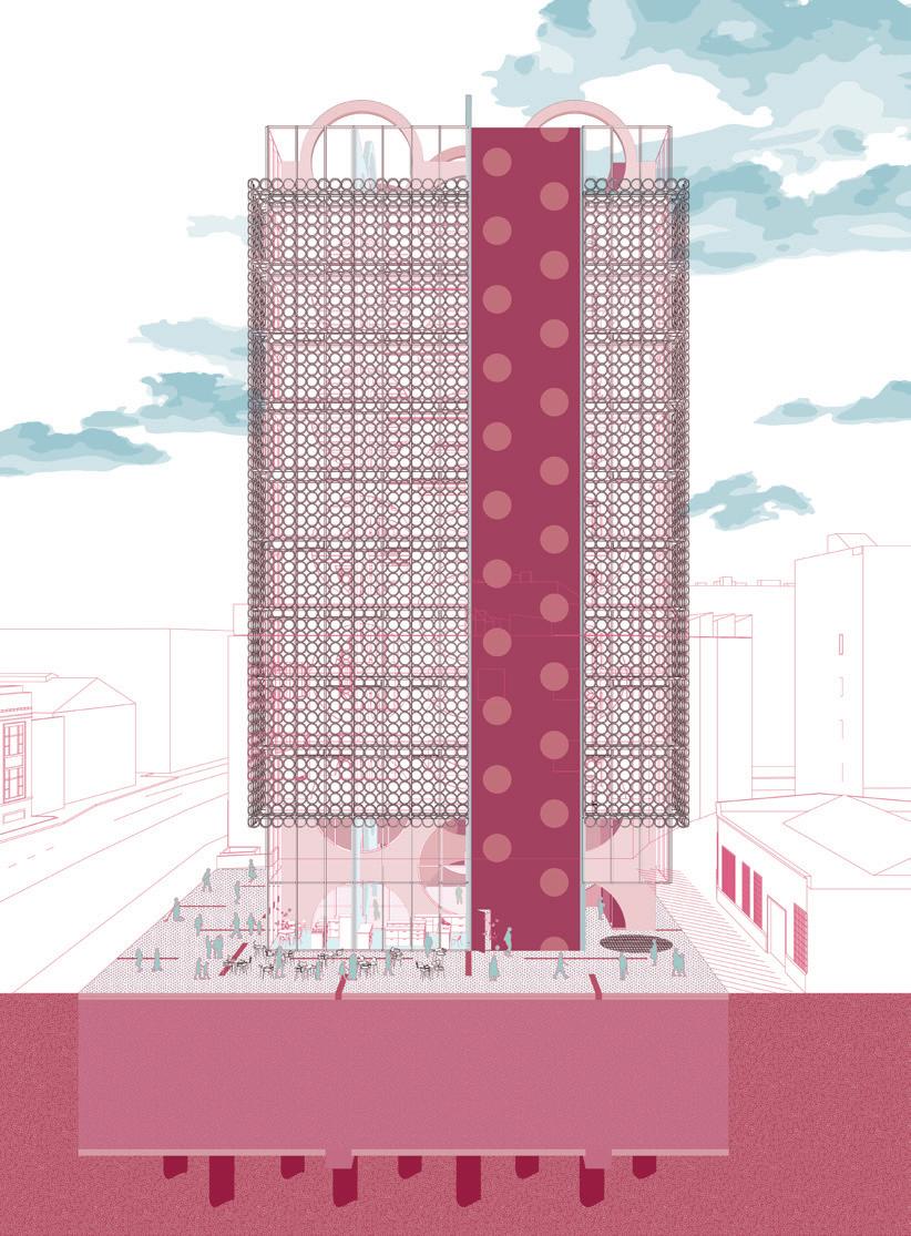
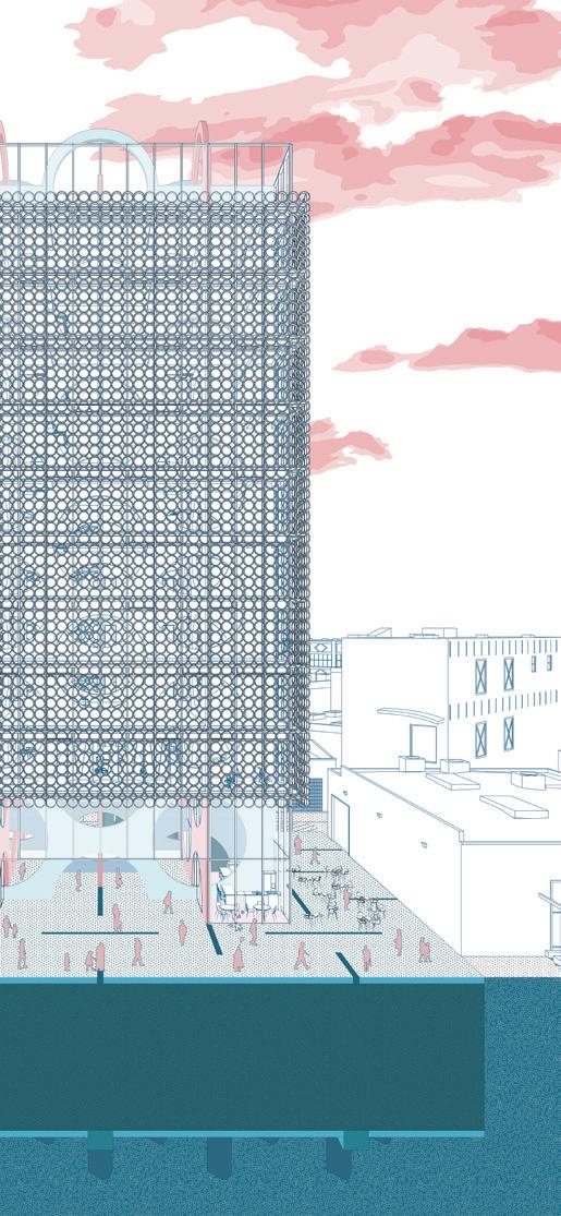
The façade is placed to regulate sunlight around the building. The facade circles act as a small-scale bris soleil, and yet views outside are not stifled. The beauty of the building is its ability to display playfulness while forming upon a strict functionally. The reading of the building displays a unique approach to a city’s vernacular and a new relationship to local architecture. Most buildings in the Arts District in Los Angeles do not provide spaces of gathering and decompression, whereas this building encourages sociability by creating a double-height space on the ground floor and adding a generous building setback from the street for interaction.
office
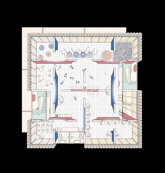
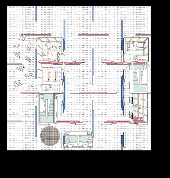
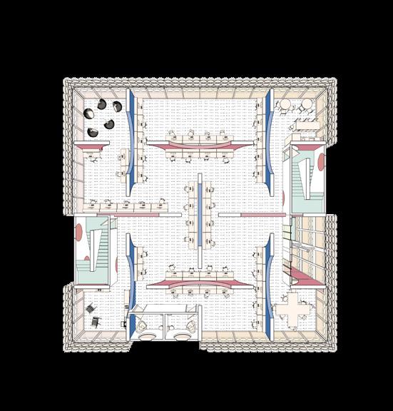
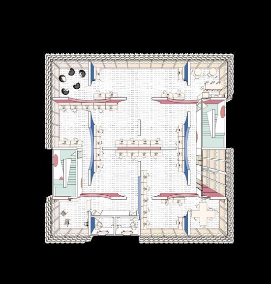
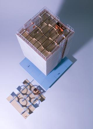
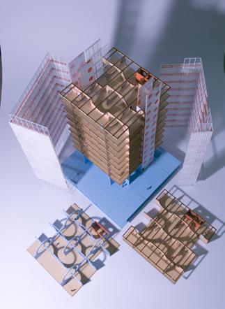
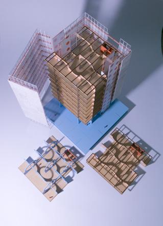
GROUND/LOBBY PLAN @ 8’ - 0” DAY CARE PLAN @ 32’ - 0” OFFICE LAYOUT 1 PLAN @ 44’ - 0” OFFICE LAYOUT 2 PLAN @ 56’ - 0”
structure+comprehensive


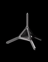
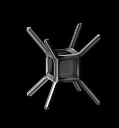
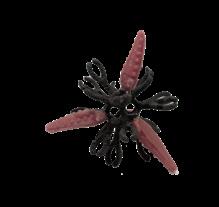
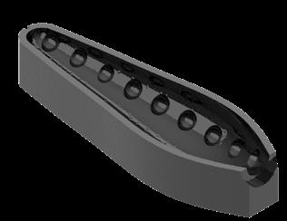
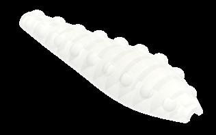
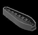
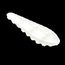
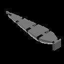
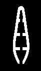
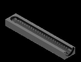
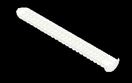
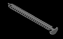
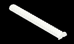
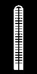
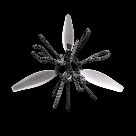
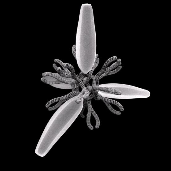
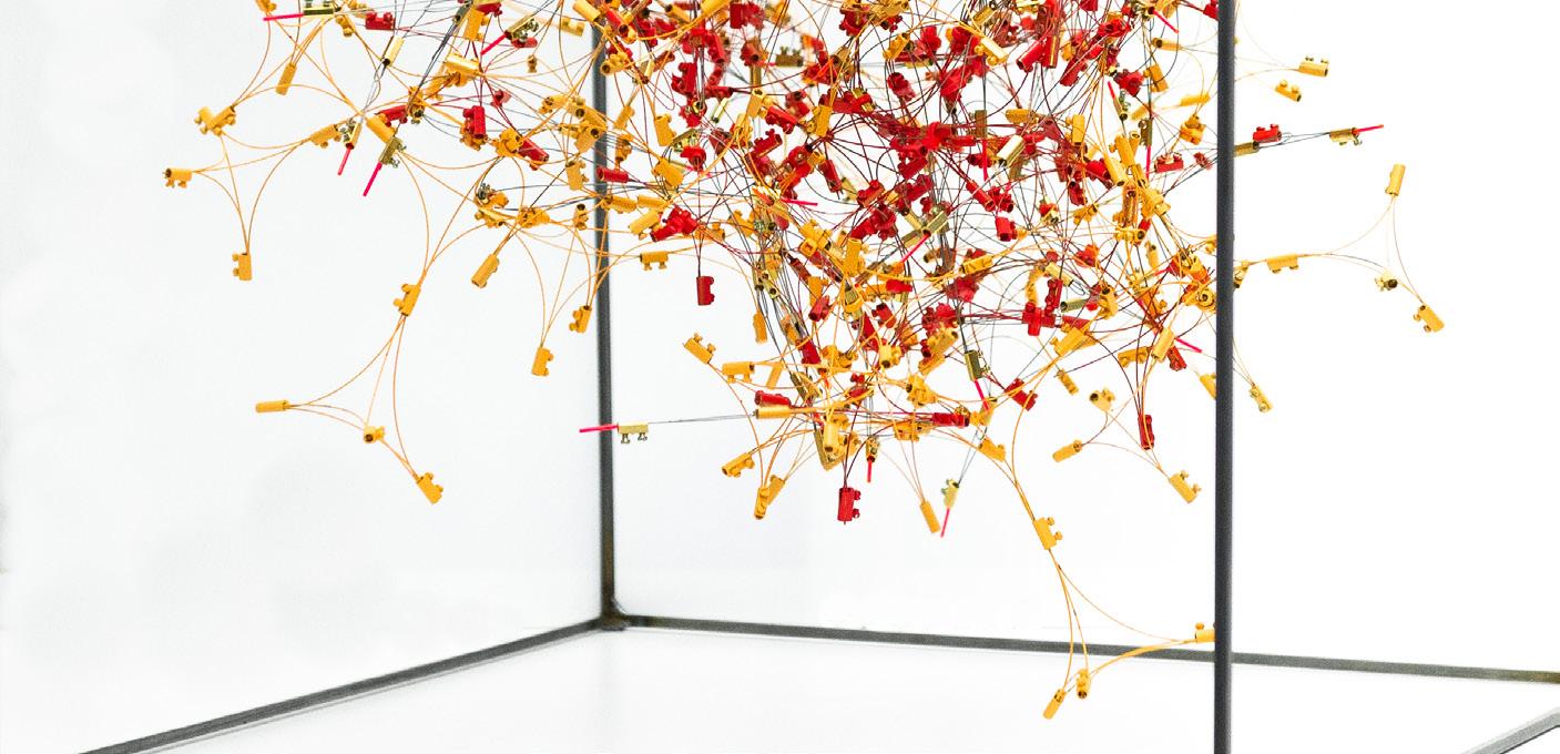
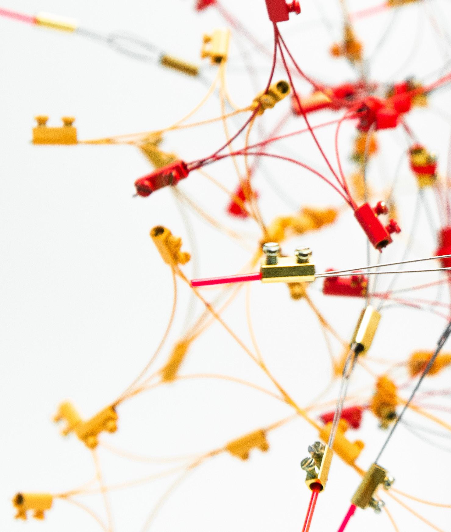
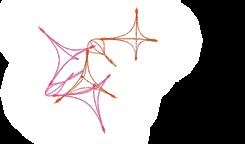
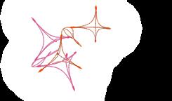
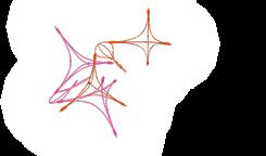
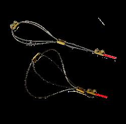
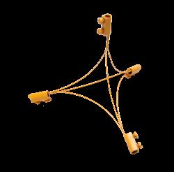
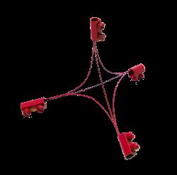
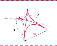
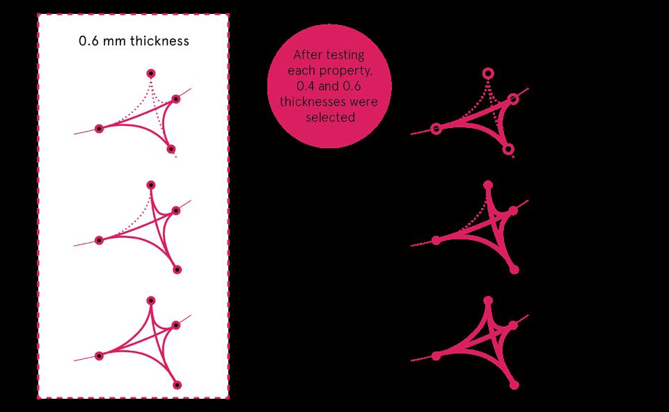
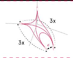
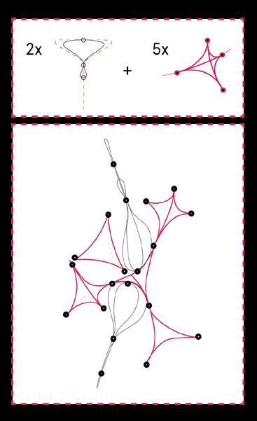
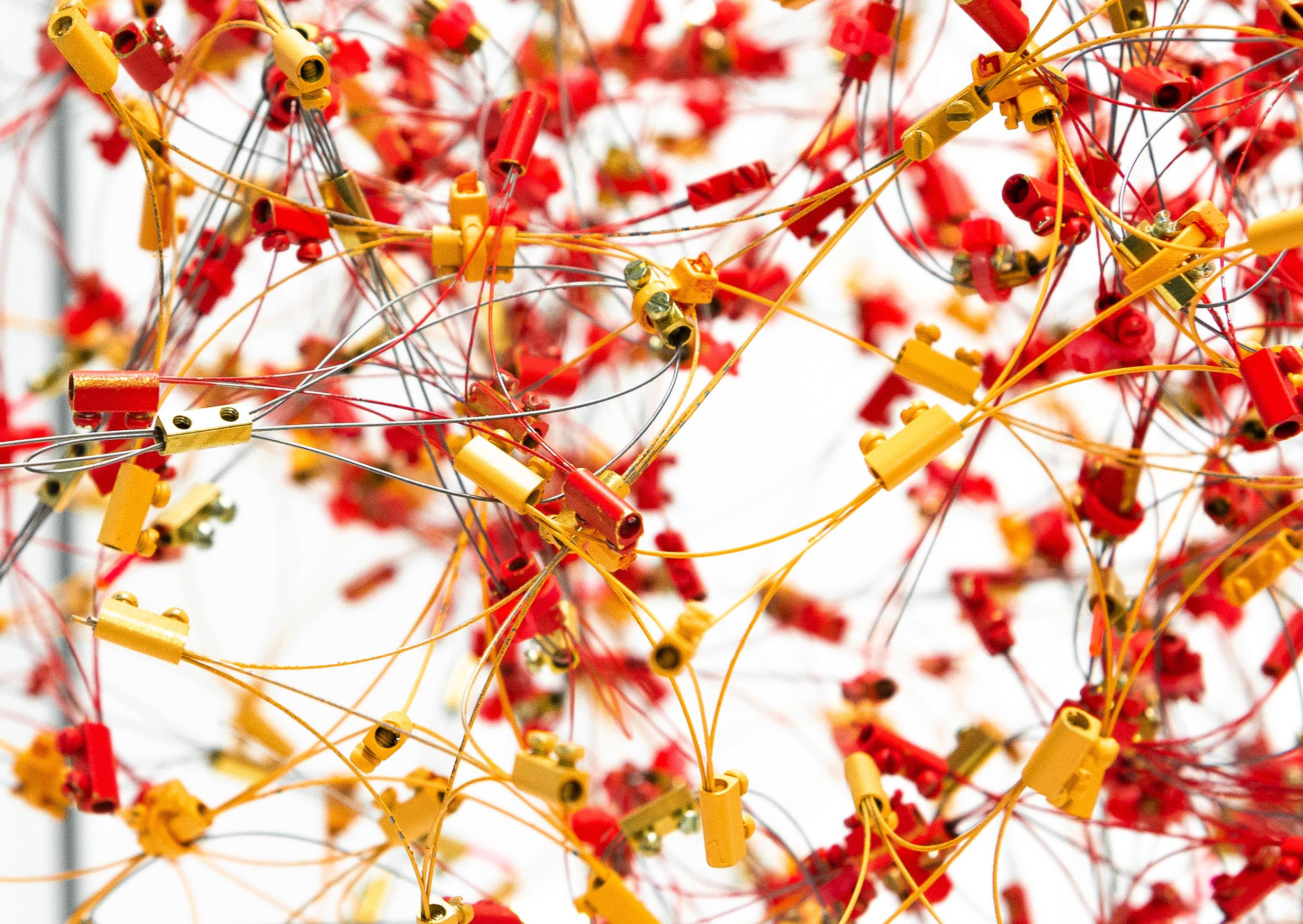
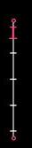
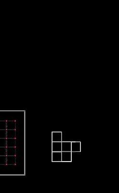
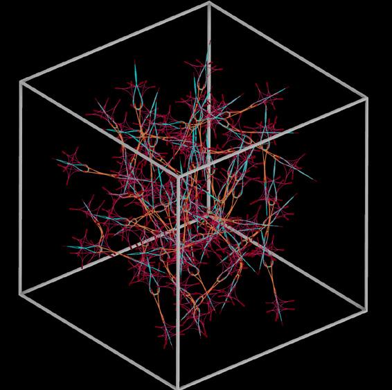
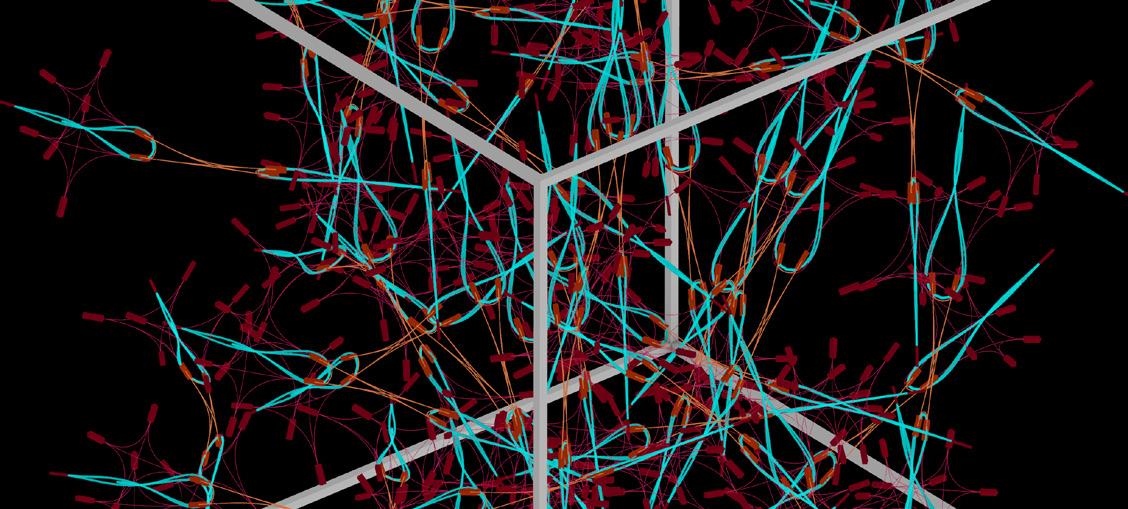
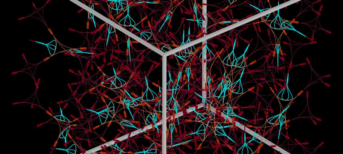
With a team of six individuals, we set out to respond to the prompt of active bending with piano wire as a medium: we created a system with discrete components that elicits a flexible whole. Our goals were to explore how different wire thicknesses affect bending properties of components as well as examine the behavior of the system clearly with a primitive, rigid geometry accompanied by a complex, active unit. Through creating a dynamic system of rigid and active bodies, we especially wanted to move away from the typical organized system, and instead we looked to cast a chaotic cloud through an organized jumble. Our module is comprised of five pyramids and two sliders. There is a center pyramid, in which every point is attached to another pyramid, comprising a five-part pyramidal structure. Including the experimentation of the slider was key to achieving an understanding of how flexible this component can be. Applying a tension feature to this element gave us an opportunity to combine wire thicknesses and lengths to locate an appropriate set of active and passive components. The connection point between two pyramids are facilitated through the attachment of our active slider component. By attaching edges of the pyramids to the mobile wire within the movable loop, we can afford a basic expansion or contraction of the space between. This prototype asserts itself as the mobile asset to its structure. The movement we assigned to the object was expanding and contracting in its outer line as controlled by an unspecified user. Exploration of formation encapsulated a single-wire component that attaches itself onto a rigid structure as a symbiotic parasite.
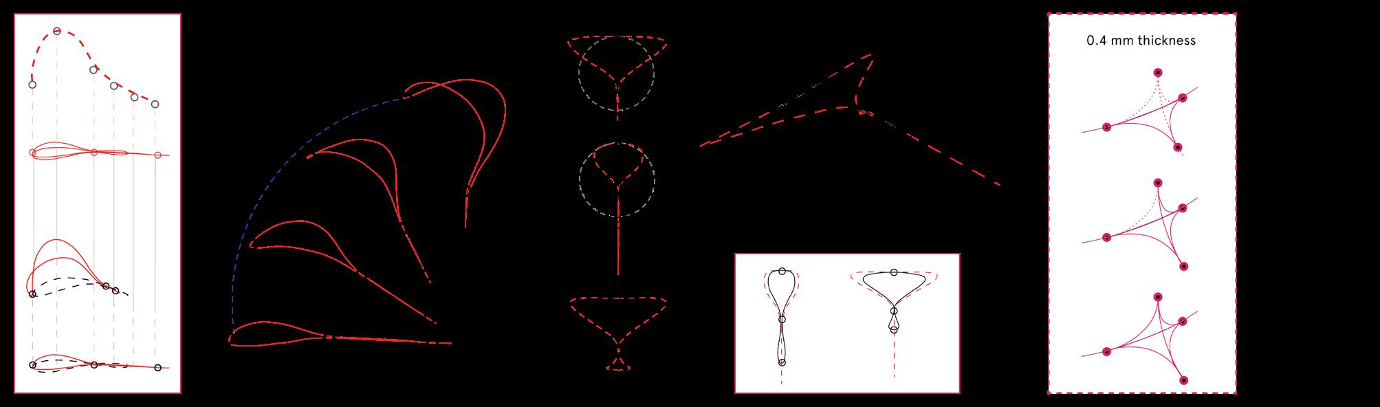
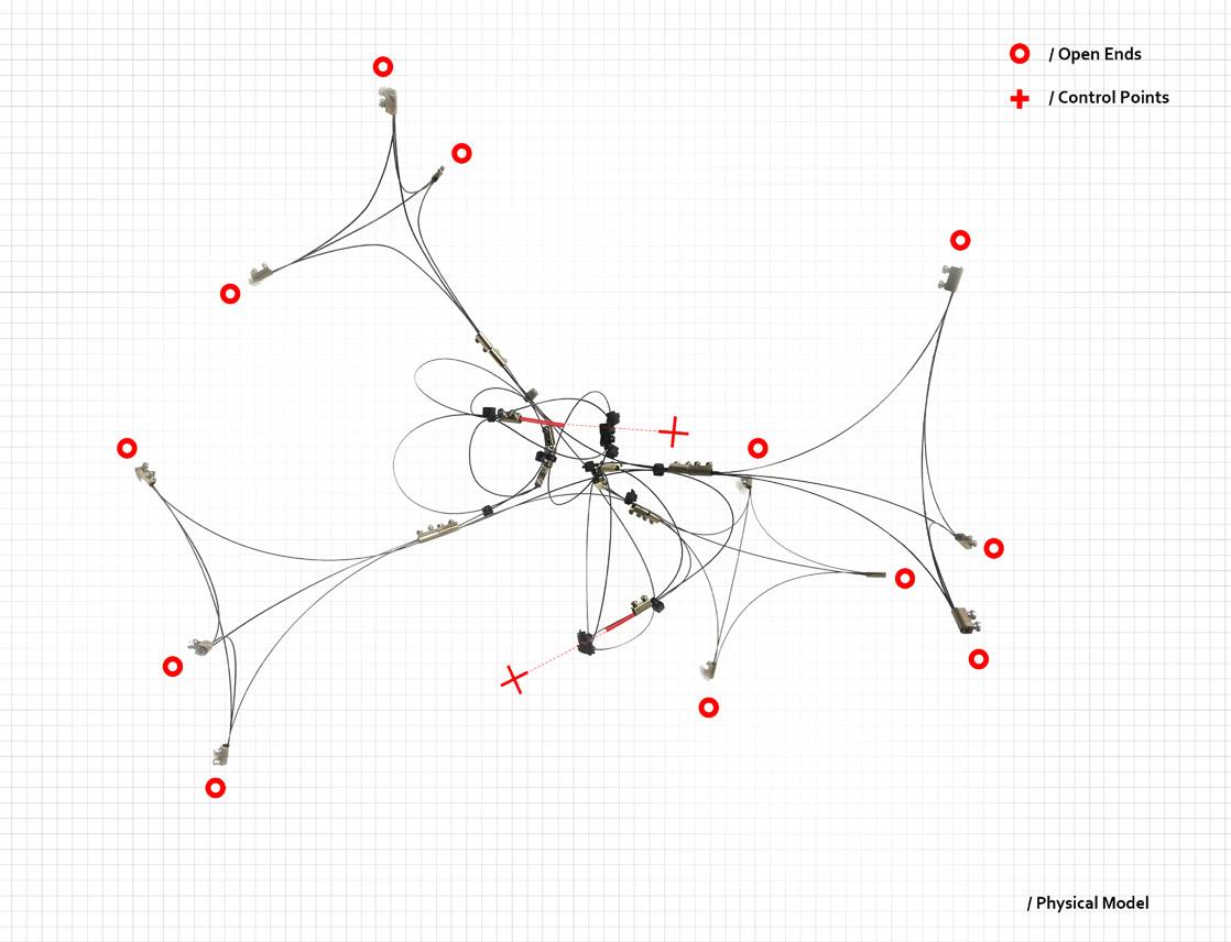
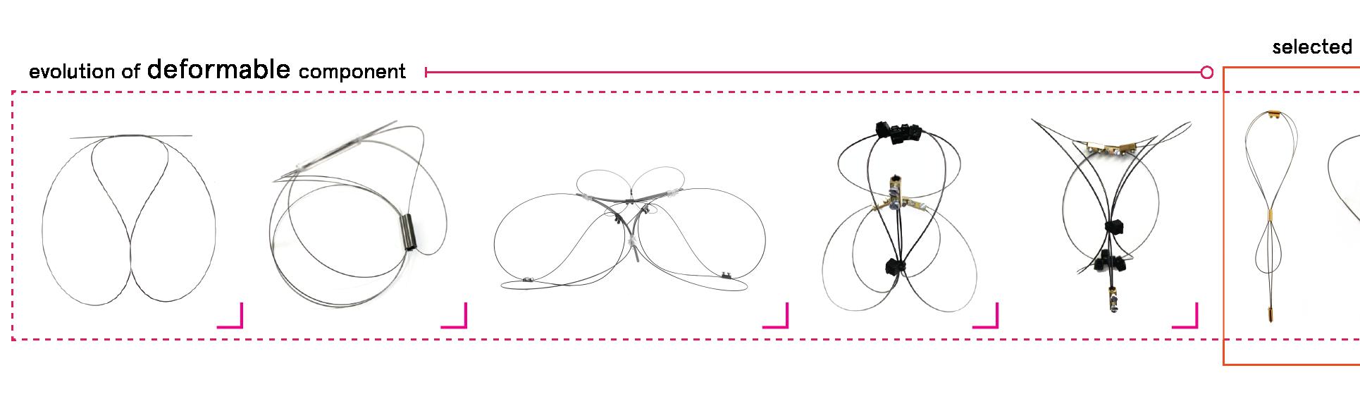
out of stock AA DRL component
+ component type 01 + component type 02
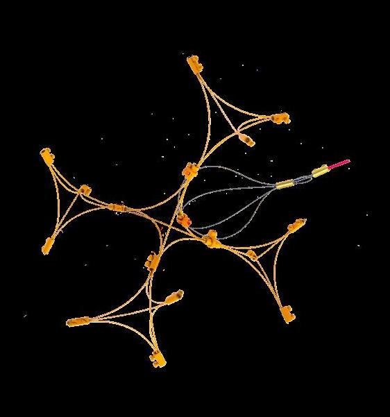
+ ORANGE
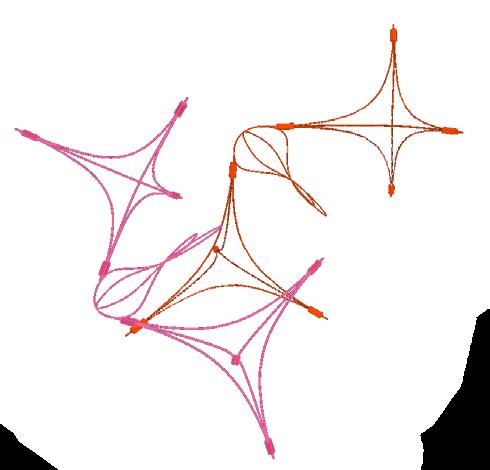
+ 1 SLIDER

+ 1 CONNECTION
+ component type 03
active+passive
simulation open components
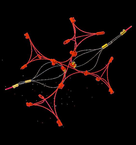


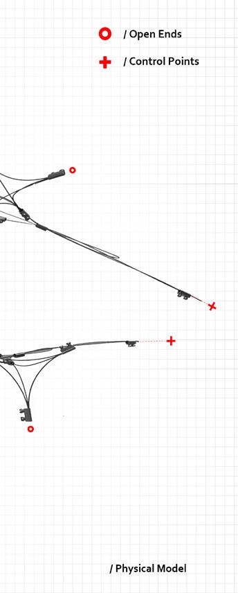
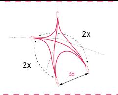
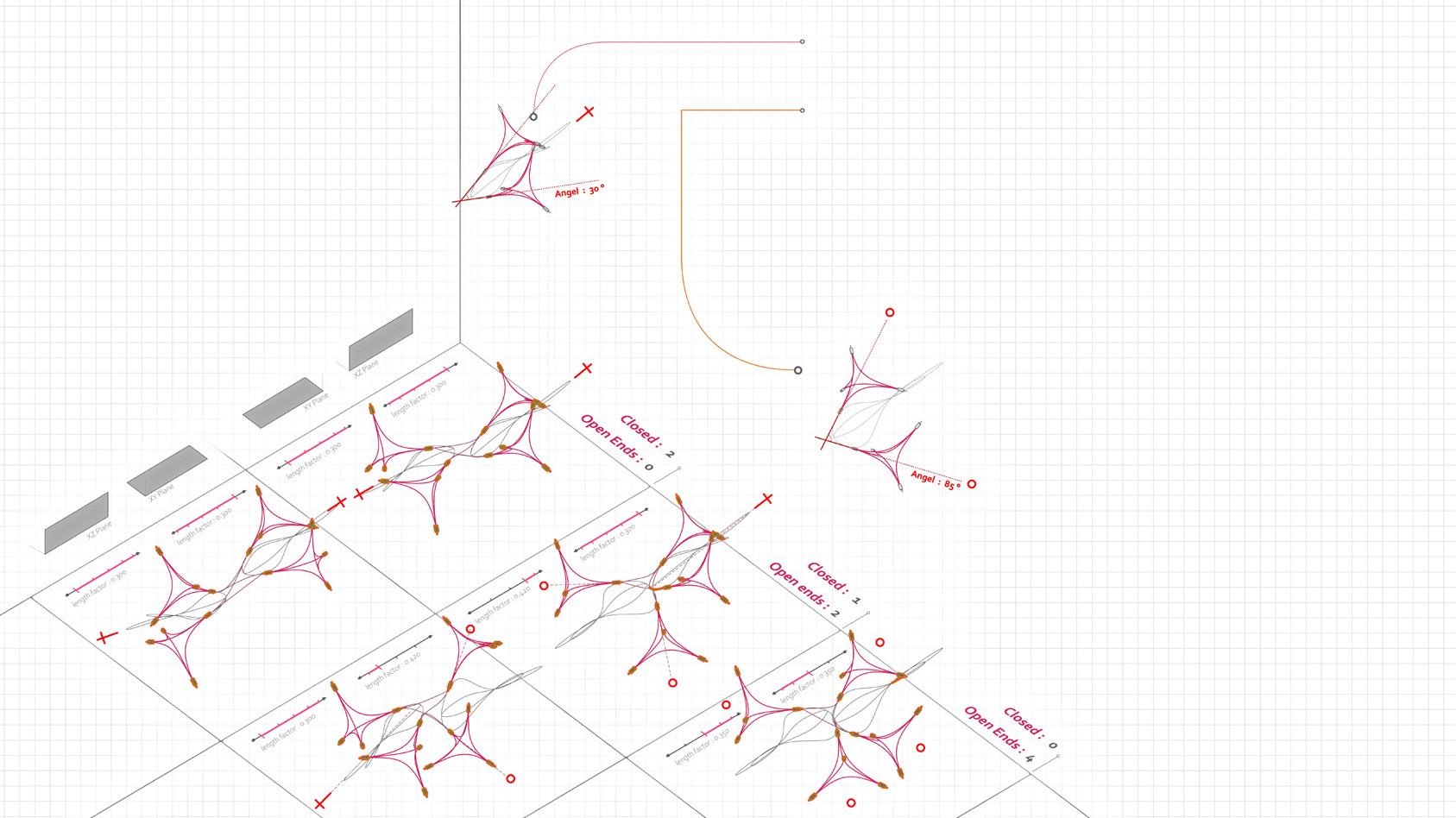
closed components


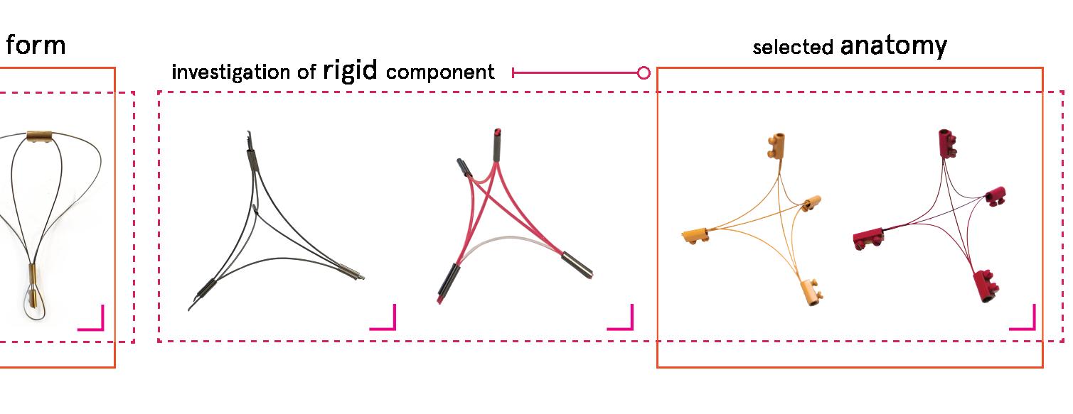
+ RED
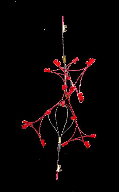
+ 2 SLIDERS
+ 2 CONNECTIONS
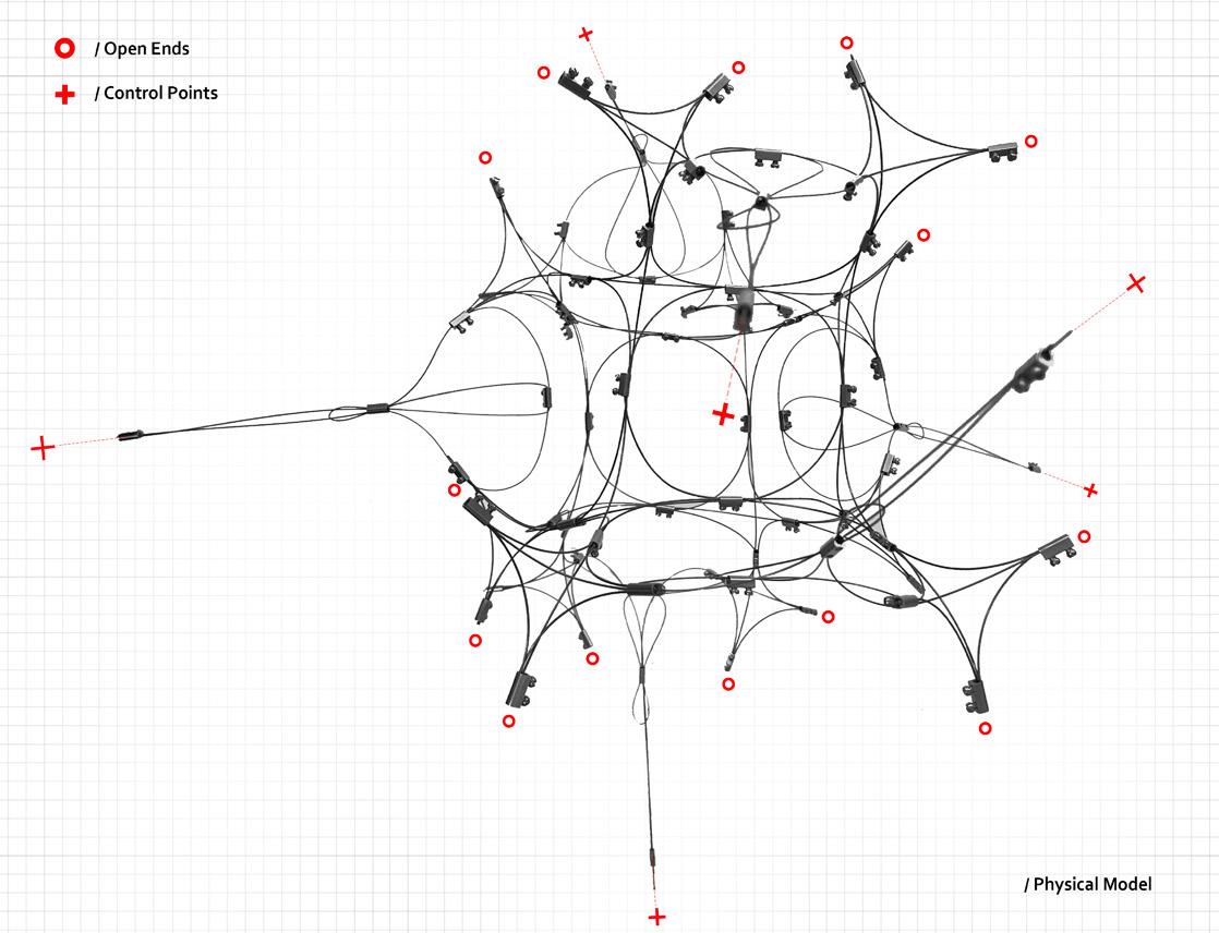
/ State 1 / State 4 / State 2 State 5 / State 3 / State 6
+ connection of the basic unit
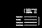
ORGANIC/CHAOTIC
Stability:
Flexibility:
Density:
GRID/TRIANGLE
Stability:
Flexibility:
Density:
GRID/RECTANGLE
Stability:
Flexibility:
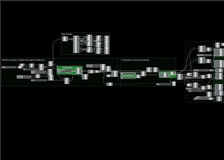
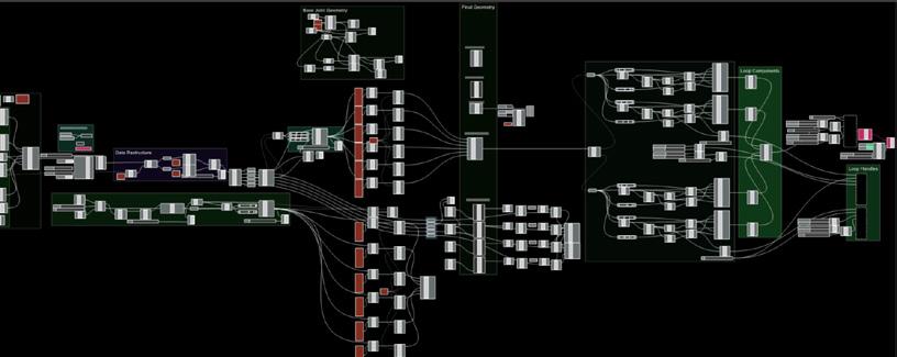
Density: grasshopper kangaroo script
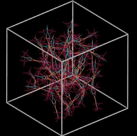
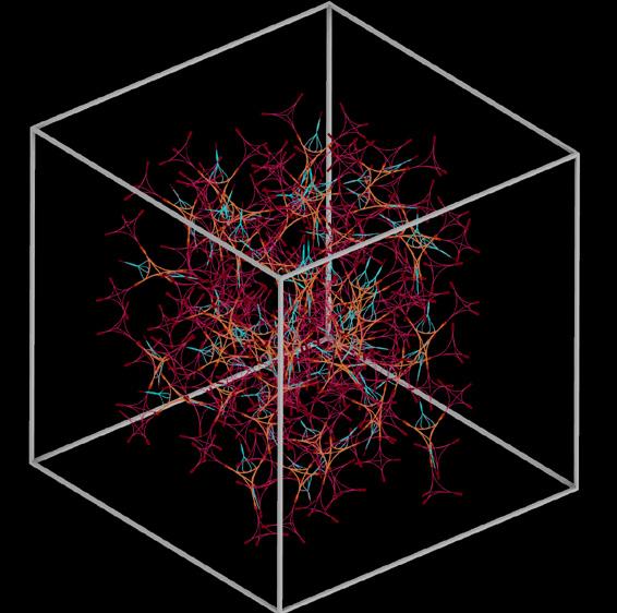
aggregation
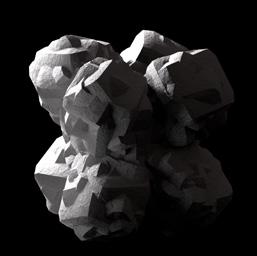
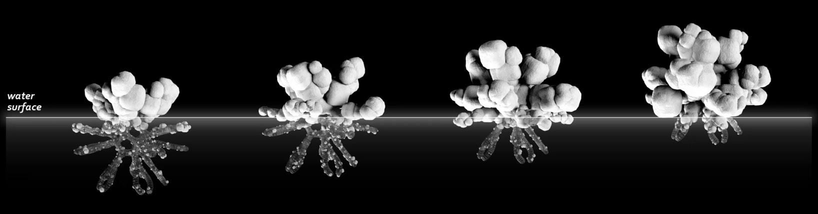
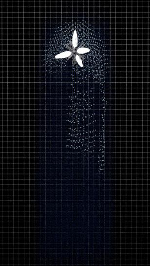
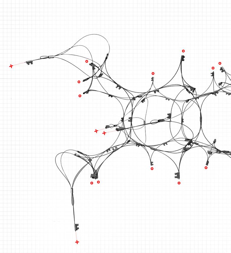
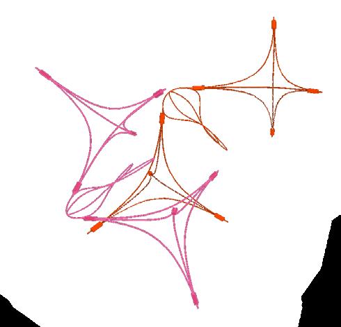
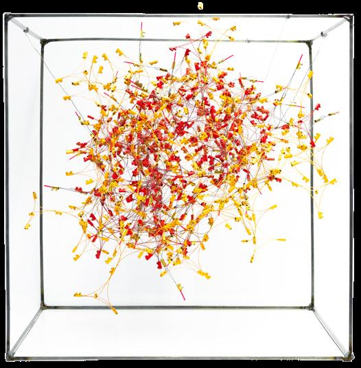
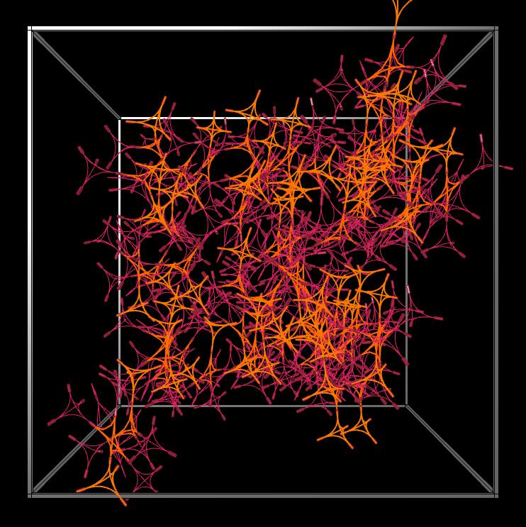
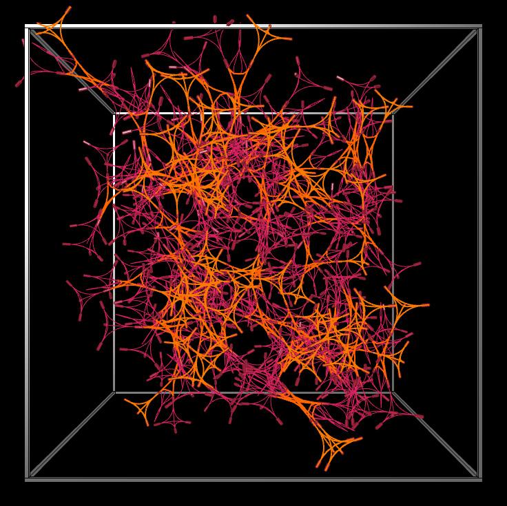
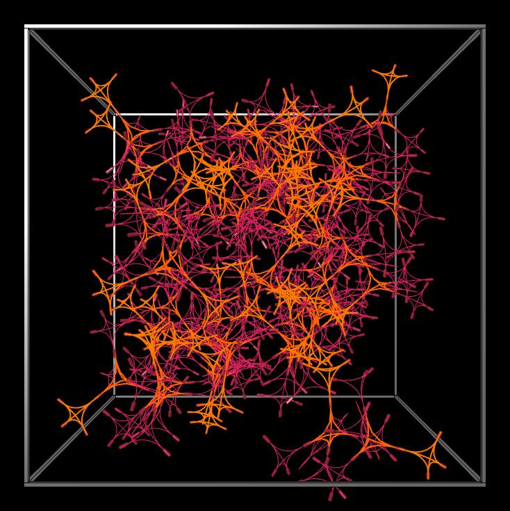
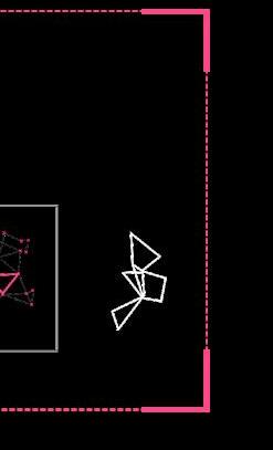
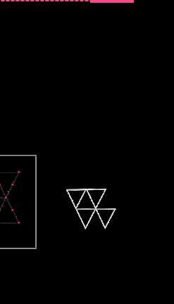
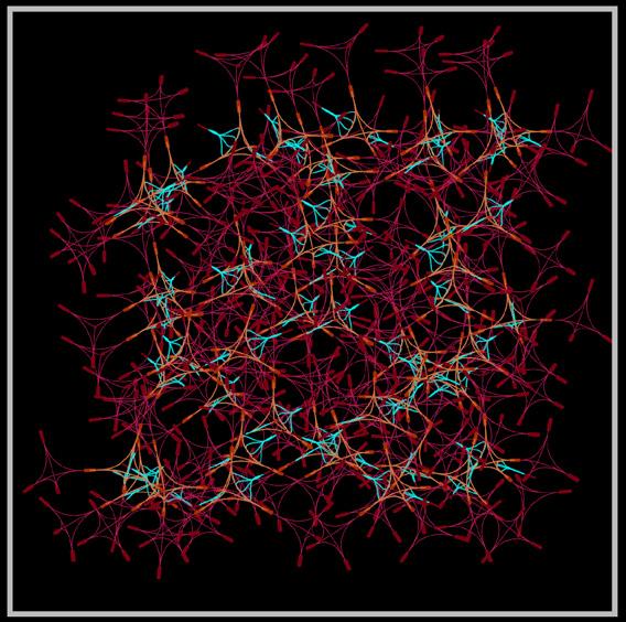
Deciding to build a cloud aggregation stemmed from the ability to provide more configurations in output and sufficient high-density transformable assemblies. We experimented with the three main types of systems in the frame: the well-organized system, rectangular grid, and triangular grid. They performed well as they presented more flexibility but did not meet our expectations in stability and density. We opted for a more disordered, chaotic, and organic system where the basic units are connected with more complexity.
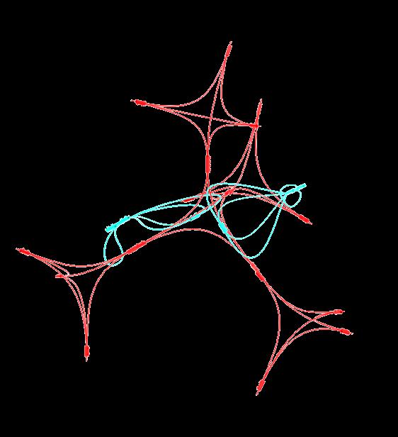
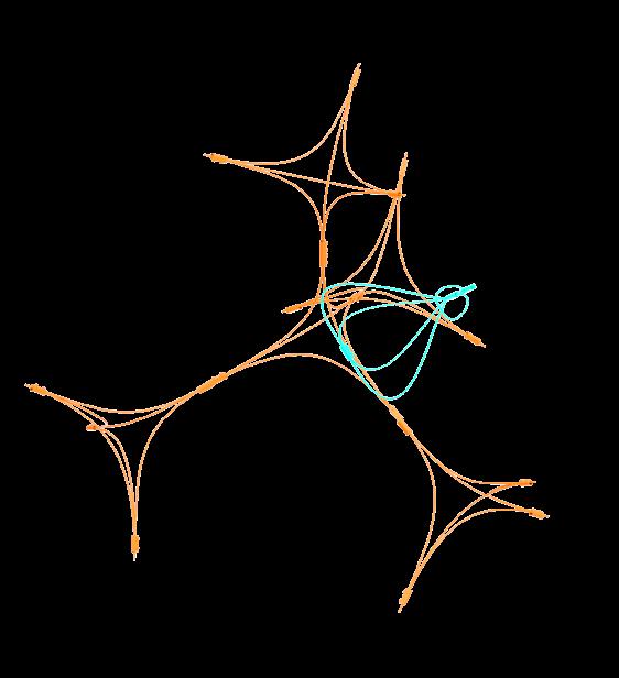
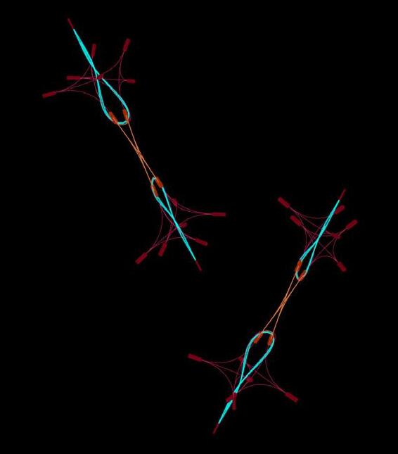
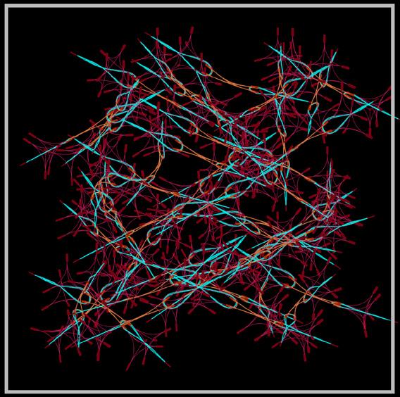
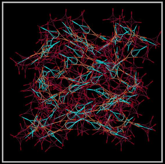
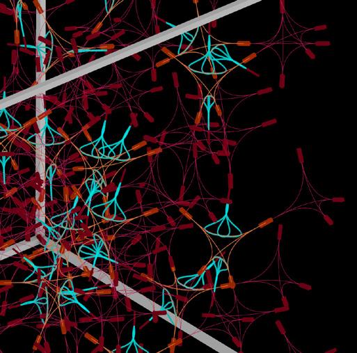
Part of the workshop task was to simulate active bending using Kangaroo on Grasshopper. Selfaggregation is digitally assumed by populating points in a spherical volume, similar to the state of the physical aggregation. The forces of gravity, friction, component collision, and slider pull for point adjustment led to an initial rest state. During simulation, the system changed state from loose to taut, identified by the cyan sliders.


ORGANIC/CHAOTIC High Low High GRID/TRIANGLE Medium Medium Low GRID/RECTANGLE Low High Medium
active component _ ‘unlocked’ active component _ ‘locked’ / Simulation_S2 Control Slider _ 0.20 Control Slider _ ii: 0.00 / Simulation_S1 Control Slider _ : 0.40 Control Slider _ ii: 0.20 / Simulation_S1 Control Slider _ i : 0.40 Control Slider _ ii: 0.00 simulation _ outputs simulation _ isometric tightening simulation _ front view tightening
thank you for your consideration