Race To Employment Robotics Guide for Beginners




01. About Race to Employment pg. 01
02. What is robotics? pg. 03
03. Safety with robotics pg. 07 04. What is electricity? pg. 11 05. Direct Current (DC) motors pg. 15 06. Microcontroller pg. 19 07. Sensors & Shields pg. 23 08. L293D Motor Driver Shield & HC-05 bluetooth module pg. 27 09. The code pg. 31


bring to their future employment; and to foster and improve the necessary competences and know-how for participants to consider seeking employment, self-employment and actively engage in entrepreneurial activities in the field of robotics.
Erasmus+ youth exchange took place in Elniakampis, Lithuania, between 22nd – 31st October, 2022 and was organized by a local organization Asociacija “Keliauk pirmyn”. The project gathered 40 participants and 8 group leaders from 4 different countries: Lithuania, Romania, Slovakia and Estonia for a 10-day adventure. It was a miraculous experience for all, even the facilitators and organisers themselves. The goal of the project was to familiarize the participants with digital education, namely robotics and increase relevant competences to seek employment or to become entrepreneurs in this field.
The Erasmus+ project “Race To Employment” consisted of facing the problem of low employability in youth and inspire young people’s active involvement in entrepreneurial activities by developing skills in robotics and raising awareness of this field as a solution for employment and self-employment. Objectives of the project were to present the participants to the robotics field of digital education by constructing fully functioning RC cars from start to finish; to raise the awareness of the participants and their communities to the opportunities that digital competences, namely robotics, can
With the motivation and dedication of the participants the objectives of the project were fully reached and even exceeded the expectations. The participants got introduced to the Erasmus+ programme and its’ opportunities, the 8 key competences and the Youthpass certificate, entrepreneurship and robotics situations in each participating country, they managed to find similarities and differences between the ones, they got introduced to robotics, safety with robotics, basics of electric circuits, electric motors, Arduino universe, various sensors and shields, basic commands and coding, they created their first micro-controlled circuit, scrapped optical drives by doing which they also kept the green course of reusing, planned the remote controlling motors, assembled and tested their RC cars, and the best part is that they did all this using non-formal education methods! The participants also visited Vilnius during the study visit, interacted with the local youth, introduced them to our project and the Erasmus+ programme. What is more, they interacted with the entrepreneurial businesses from the capital city that specialized or were associated to the robotics by taking short interviews! That was a really great day.
The project was crowned with the public event – The Race – during which the participants were racing
the RC cars that they constructed in three different competitions: drag race, off-road race and beauty competition. The race had three different winners in these competitions. The participants were very happy to successfully fulfil the race.
It was a great experience for all, and the testimonials written by the participants themselves is a living proof of that. They experienced interculturality at its best, found friends for life and learned so much more than the framework of this project. They were the reason for

such a success of the project and the organisers are very thankful for each one who participated. We would also like to thank to the facilitators of the project who led the way through the learning process and helped along the way.
We cannot wait to see our participants in the future and see how their paths turned towards entrepreneurship and robotics!
The participants of “Race To Employment” project contributed to completing this Robotics Guide for Beginners.
Asociacija “Keliauk pirmyn”, 2022


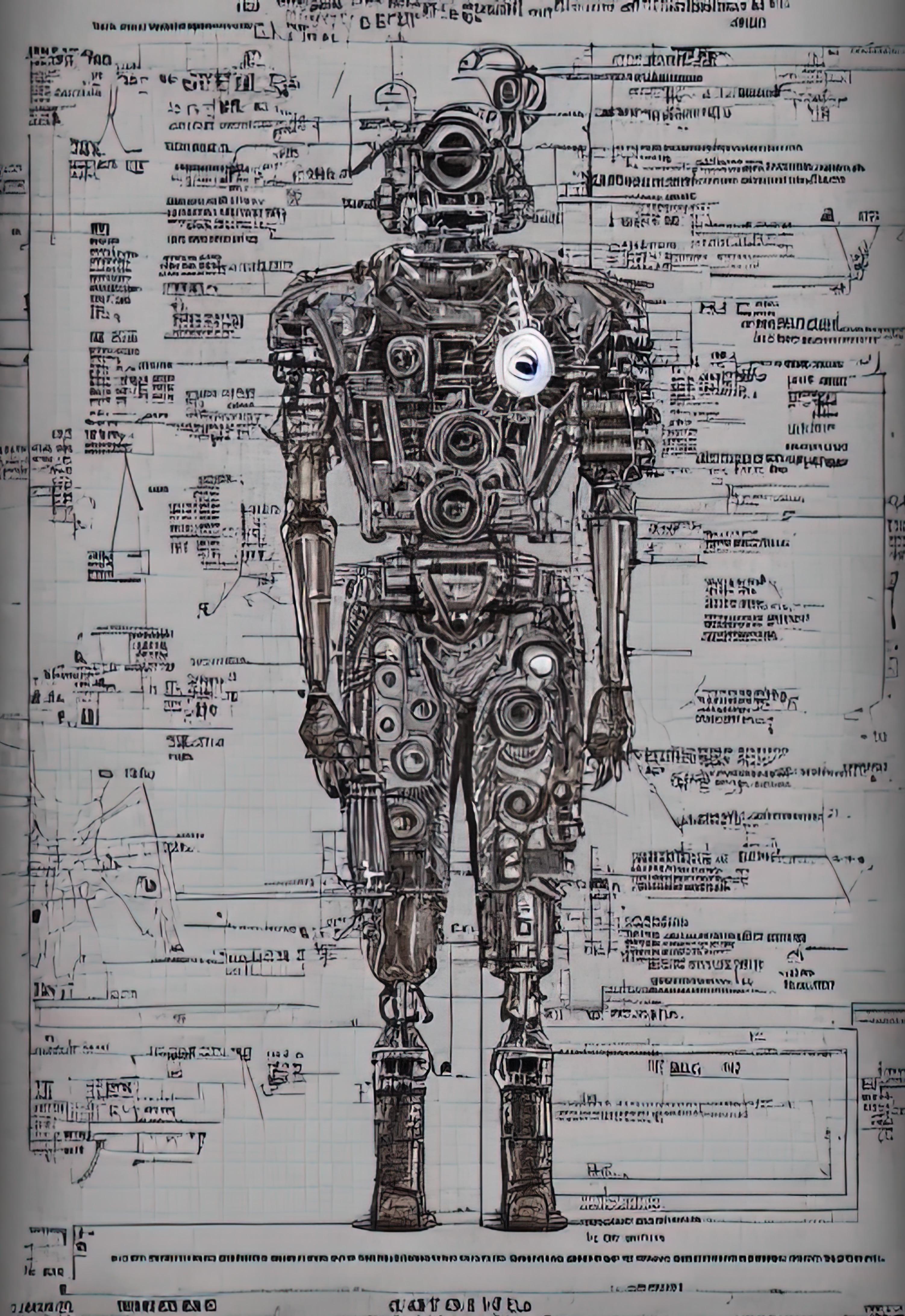
Robotics is a branch of engineering involving conception, design, manufacturing, programming, and operating robots.[1]
The word “robot” was used the first time in 1920 by the Czech novelist Karol Čapek in his play Rossum’s Universal Robots. The word robot comes from the Czech word „robiť“ which means forced labour.
In 1940’s the sci-fi writer Isaac Asimov wrote down 3 Laws of robotics:
1. Robots must never harm human beings
Z22, CC BY-SA 4.0 <https://creativecommons.org/licenses/by-sa/4.0>, via Wikimedia Commons
2. Robots must follow instructions from human without violating first rule 3. Robots must protect themselves without violating other two rules[2]
The first type of robot we talked about is a mechanical robot or Automaton.
Automatons have a very long history, the first ones used to draw pictures and write poems. Now they are only for arts.
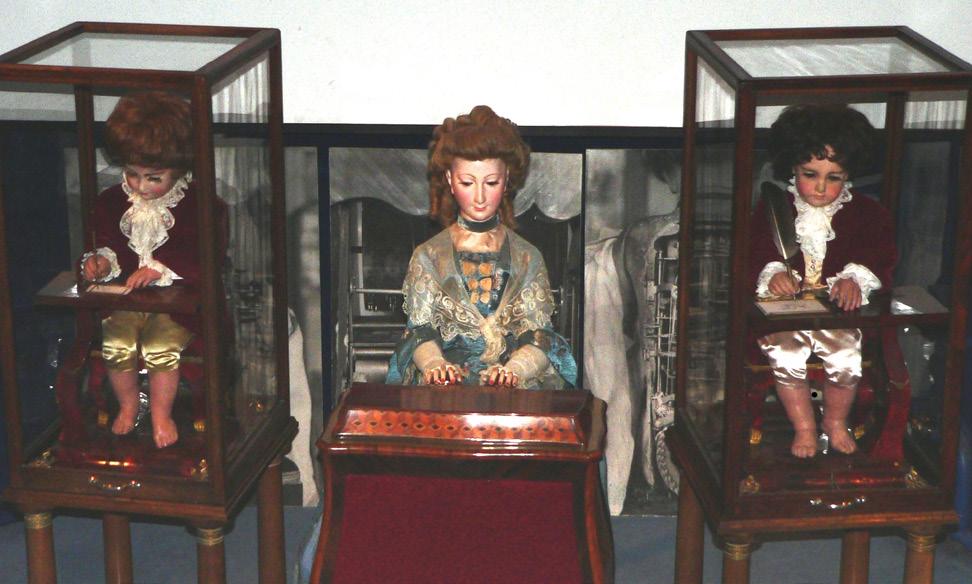
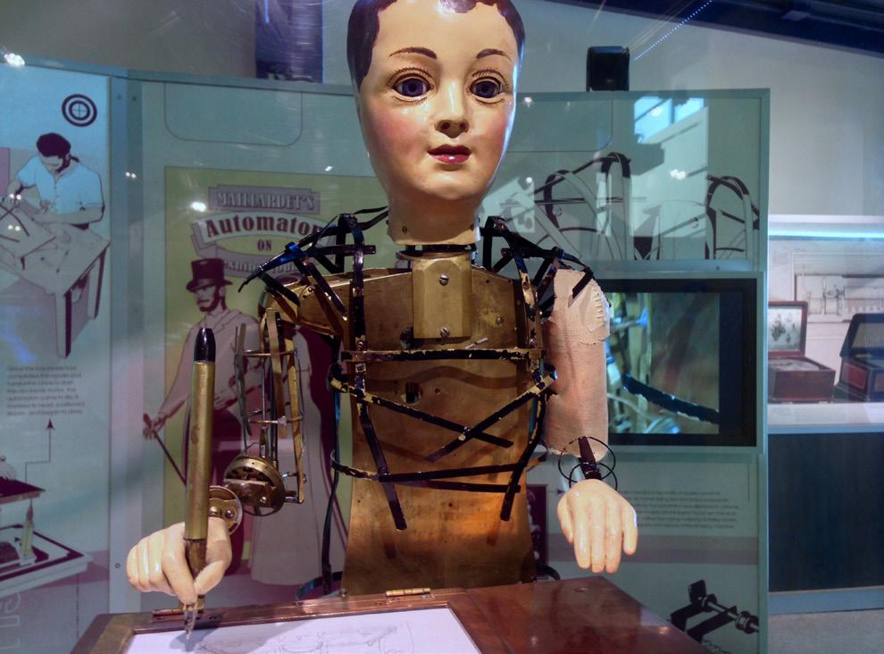
By Rama - Own work, CC BY-SA 2.0 fr, https://commons.wikimedia.org/w/ index.php?curid=481541
Robots that are most common now are programmable ones that first appeared in 1960’s. These are mostly composed of microelectronics not cogs and gears, which makes them more complex but more accessible and more easily programmable. That’s the type of robot we created. This type of robot is used heavily in the manufacturing industry, for example robotic arms that replace people in repetitive or physically demanding jobs.
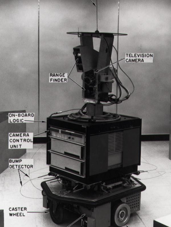
Shakey was the first general-purpose mobile robot able to reason about its own actions. It was working based on inputs from sensors. This robot combined robotics, computer vision and language processing. Shakey was developed at the A.I. Center of Stanfordcalc. It was the first mobile robot.[3][4]
By SRI International - SRI International, CC BY-SA 3.0, https://commons.wikimedia.org/w/index.php?curid=17294520
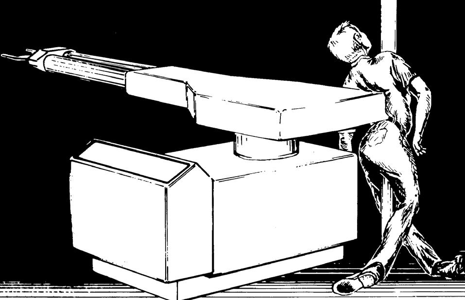
Safety is a really important aspect in robotics, Today’s industrial robots can be fatal when safety protocols are not followed.
They present a danger to workers around them, particularly when people have to interact with a robot during programming, maintenance, testing, setup or adjustment.
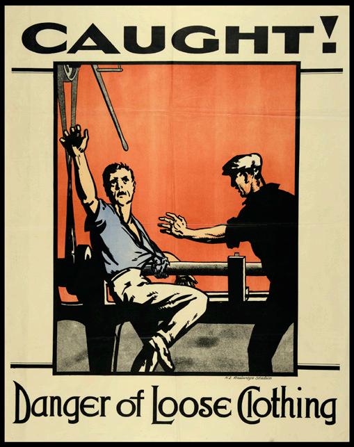
In general, workplace robotics safety is an aspect of occupational safety and health, when robots are used in the workplace.

There are eight rules of robotic safety, which the employers of robotics area must know: 1.
 By
By
KUKA Roboter GmbH, Bachmann - KUKA Roboter GmbH https://commons.wikimedia.org/w/index.php?curid=3345405
By Bilboq - Own work, Public Domain, https:// commons.wikimedia.org/w/index.php?curid=1118420
Archives New Zealand from New Zealand, CC BY-SA 2.0 <https:// creativecommons.org/licenses/by-sa/2.0>, via Wikimedia Commons
Rooooo, CC BY-SA 3.0 <https://creativecommons. org/licenses/by-sa/3.0>, via Wikimedia Commons
6. Locate the emergency stop pushbutton
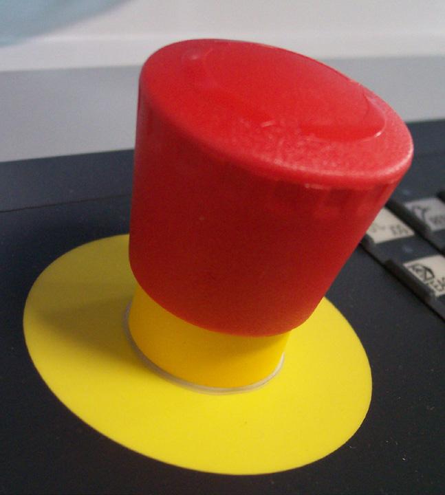
The important thing is that, when we are talking about robotics in industrial and working areas, operators who work in this work area must have access to a device called an emergency stop pushbutton. This device must interrupt power to all aspects of the robot work cell including external and associated devices. All devices must default to a safe condition. Emergency stop pushbuttons always must be within reach of any person who is near or in the work cell area.
IP83, CC BY-SA 3.0 <http://creativecommons.org/ licenses/by-sa/3.0/>, via Wikimedia Commons
7. Ensure that safety glasses are worn by people in the area

DJSparky, CC BY-SA 4.0 <https://creativecommons. org/licenses/by-sa/4.0>, via Wikimedia Commons
8. Ensure that all people are outside the robot’s work area [5]
Safety with robotics is not only important for the employers of the robotics area, but is important for the people, who deal with robotics on a daily basis. The rules almost do not change, the main thing is that you need to be extremely careful. Every robotical object can face the upcoming sources of hazards that are associated with human interaction with robots and machines: • control errors
human errors
unauthorized access
mechanical failures
environmental sources
power systems
improper installation

Electricity is a form of energy resulting from the existence of charged particles moving as a current.[6]
Everything in the universe is made of atoms. Atoms are made of particles. The center of an atom is called the nucleus. It is made of particles called protons and neutrons.
The protons and neutrons are very small, but electrons are much, much smaller. Electrons spin around the nucleus in shells at great distance from the nucleus. The protons and electrons of an atom are attracted to each other. They both carry an electrical charge.
An electrical charge is a force within the particle. Protons have a positive charge (+) and electrons have a negative charge (-). The positive charge of the protons is equal to the negative charge of the electrons. Opposite charges attract each other. When an atom is in balance, it has an equal number of protons and electrons. The electrons in the shells closest to the nucleus have a strong force of attraction to the protons. Sometimes, the electrons in the outermost shells do not. These electrons can be pushed out of their orbits. Applying a force can make them move from one atom to another. These moving electrons are electricity.
Electricity travels in closed loops, or circuits. It must have a complete path before the electrons can move. If a circuit is open, the electrons cannot flow. The electricity flows from the electric wire through the light and back into the wire. Electricity does a lot of work for us.[7]
A generator is a device that converts mechanical energy into electrical energy. The process is based on the relationship between magnetism and electricity. In 1831, Faraday discovered that when a magnet is moved inside a coil of wire, electrical current flows in the wire.
A typical generator at a power plant uses an electromagnet, a magnet produced by electricity, not a traditional permanent magnet. The generator has a series of insulated coils of wire that form a stationary cylinder. This cylinder surrounds a rotary electromagnetic shaft. When the electromagnetic shaft rotates, it induces a small electric current in each section of the wire coil. Each section of the wire becomes a small, separate electric conductor. The small currents of individual sections are added together to form one large current. This current is the electric power that is transmitted from the power company to the consumer. An electric utility power station uses either a turbine, engine, water wheel, or other similar machines to drive an electric generator or a device that converts mechanical or chemical energy to generate electricity. Steam turbines, internalcombustion engines, gas combustion turbines, water turbines and wind turbines are the most common methods to generate electricity. Most power plants are about 35 percent efficient. That means that for every 100 units of energy that go into a plant, only 35 units are converted to usable electrical energy.[8]
Long before any knowledge of electricity existed, people were aware of shocks from the electric fish. Ancient Egyptian texts dating from 2750 BCE referred to these fish as the “Thunderer of the Nile”, and described them as the “protectors” of all other fish. Electric fish were again reported millennia later by ancient Greek, Romanand Arabic naturalists and physicians.
Ancient cultures around the Mediterranean knew that certain objects, such as rods of amber, could be rubbed with cat’s fur to attract light objects like feathers. Thales of
Miletus made a series of observations on static electricity around 600 BCE, from which he believed that friction rendered amber magnetic, in contrast to minerals such as magnetite, which needed no rubbing.[9]
Electricity would remain little more than an intellectual curiosity for millennia until 1600, when the English scientist William Gilbert wrote De Magnete, in which he made a careful study of electricity and magnetism, distinguishing the lodestone effect from static electricity produced by rubbing amber.
Further work was conducted in the 17th and early 18th centuries by Otto von Guericke, Robert Boyle, Stephen Gray and C. F. du Fay. Later in the 18th century, Benjamin Franklin conducted extensive research in electricity, selling his possessions to fund his work.[10]
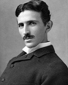
While the early 19th century had seen rapid progress in electrical science, the late 19th century would see the greatest progress in electrical engineering. Through such people as Alexander Graham Bell, Ottó Bláthy, Thomas Edison, Galileo Ferraris, Oliver Heaviside, Ányos Jedlik, William Thomson, 1st Baron Kelvin, Charles Algernon Parsons, Werner von Siemens, Joseph Swan, Reginald Fessenden, Nikola Tesla and George Westinghouse, electricity turned from a scientific curiosity into an essential tool for modern life.
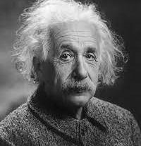
In 1905, Albert Einstein published a paper that explained experimental data from the photoelectric effect as being the result of light energy being carried in discrete quantized packets, energising electrons. This discovery led to the quantum revolution.[11]
Nowadays people use electricity for almost everything: lighting, heating, cooling, and operating appliances, electronics, machinery.
by Orren Jack Turner, Princeton, Modified with Photoshop by PM_Poon and later by Dantadd. Public domain, via Wikimedia Commons
DIRECT CURRENT (DC) is an electrical current which flows constantly in one direction. The current that flows in a flashlight or another appliance running on batteries is a direct current.[12]
Examples: Computers, mobile phone batteries, flashlights, electric cars, TV screens, LED lightbulbs.
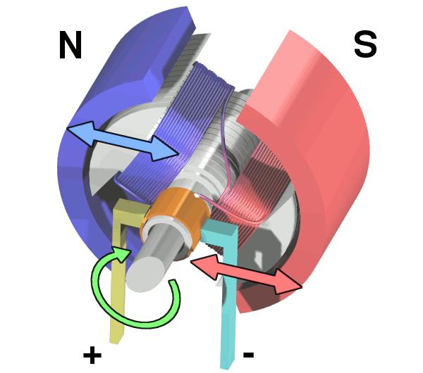
A brushed DC electric motor is an internally commutated electric motor designed to be run from a direct current power source and utilizing an electric brush for contact. Magnets are placed on stator and coils on rotor.[13]

Examples: Paper machine, cranes, electrical propulsion, sewing machines, power tools.
By Wapcaplet - Electric Motor Cycle, CC BY-SA 3.0, https://commons.wikimedia.org/w/index.php?curid=671789
A brushless motor is a direct current (DC) electric motor that operates without the mechanical brushes. Magnets are placed on rotor and coils on stator.
Benefits: High power-to-weight ratio, High speed, Nearly instantaneous control of speed, High efficiency,Low maintenance.
Examples: CD drives, power tools, drones, EV.
By Sebastian Koppehel - Own work, CC BY 3.0, https://commons.wikimedia. org/w/index.php?curid=2747626
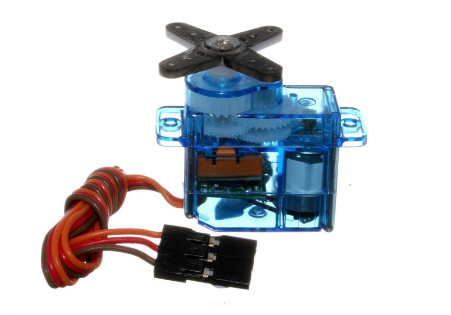
Electronic devices and rotary or linear actuators that rotate and push parts of a machine with precision.
Examples: Robotics, pharmaceutics, food services, in-line manufacturing.
By oomlout - SERV-03-MI (Micro Servo), CC BY-SA 2.0, https://commons.wikimedia.org/w/index.php?curid=19867075
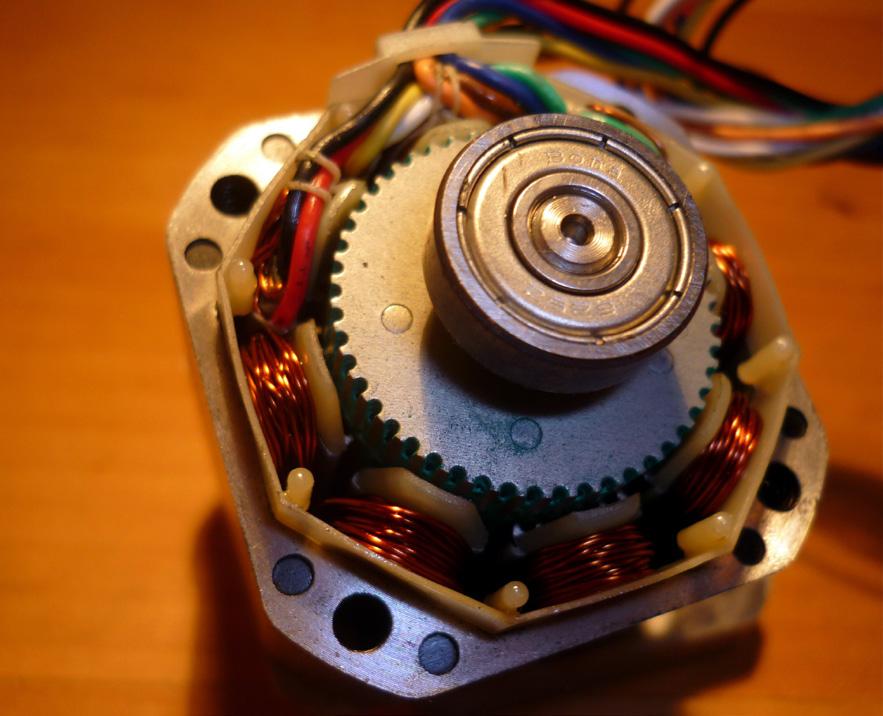
Brushless DC motor that has low RPM, but has a lot of torque and very high positioning precision.
Examples: 3D printers, CNC machines, camera lenses, platters.
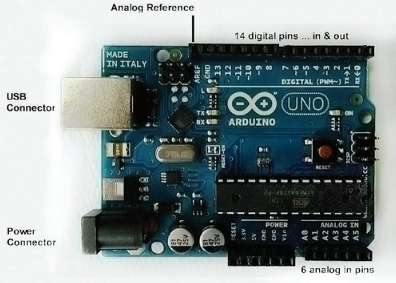
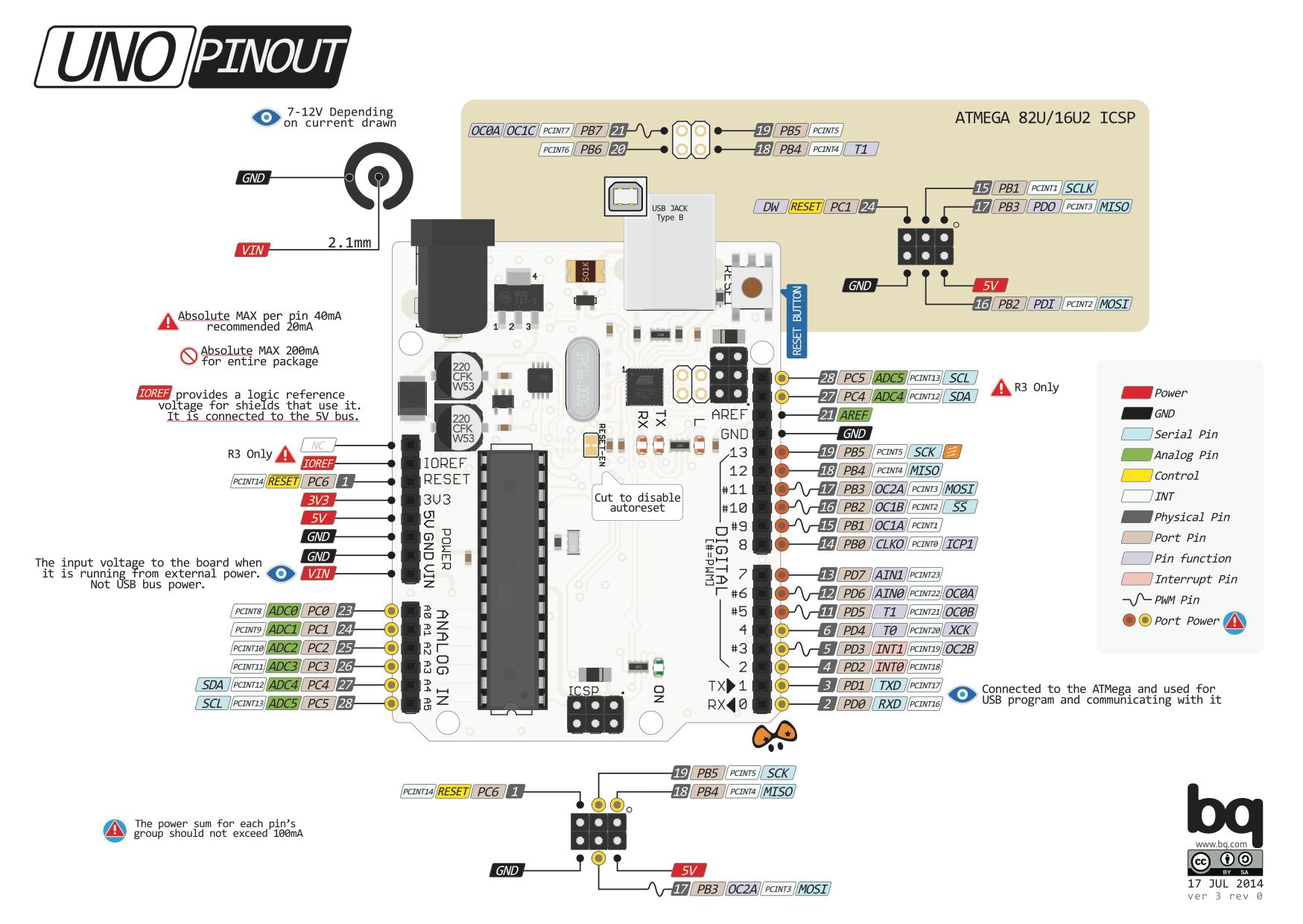
The Arduino Uno is a open-source microcontroller board based on the Microchip ATmega328P microcontroller and developed by Arduino.cc and initially released in 2010.
The word “uno” means “one” in Italian and was chosen to mark the initial release of Arduino Software.
The ATmega328 on the board comes preprogrammed with a bootloader that allows uploading new code to it without the use of an external hardware programmer.
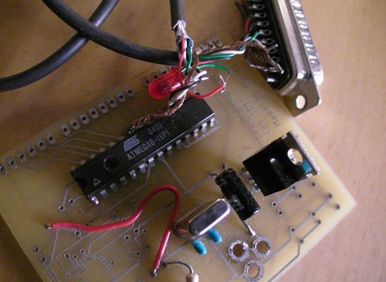
1sfoerster, CC BY-SA 3.0 <https://creativecommons.org/licenses/by-sa/3.0>, via Wikimedia Commons
The Arduino Uno has a number of facilities for communicating with a computer, another Arduino board, or other microcontrollers.
The Arduino project started at the Interaction Design Institute Ivrea (IDII) in Ivrea, Italy. At that time, the students used a BASIC Stamp microcontroller, at a cost that was a considerable expense for many students. In 2003, Hernando Barragán created the development platform Wiring as a Master’s thesis project at IDII, under the supervision of Massimo Banzi and Casey Reas, who are known for work on the Processing language.
The project goal was to create simple, low-cost tools for creating digital projects by non-engineers.
The Wiring platform consisted of a printed circuit board (PCB) with an ATmega168 microcontroller, an IDE based on Processing, and library functions to easily program the microcontroller. In 2003, Massimo Banzi, with David Mellis, another IDII student, and David Cuartielles, added support for the cheaper ATmega8 microcontroller to Wiring. But instead of continuing the work on Wiring, they forked the project and renamed it Arduino. Early Arduino boards used the FTDI USB-to-serial driver chip and an ATmega168.
The Uno differed from all preceding boards by featuring the ATmega328P microcontroller and an ATmega16U2 (Atmega8U2 up to version R2) programmed as a USB-to-serial converter.
By Philliptorrone - Own work, CC BY-SA 3.0, https://commons.wikimedia.org/w/ index.php?curid=19269741• LED: There is a built-in LED driven by digital pin 13. When the pin is high value, the LED is on, when the pin is low, it is off.
• VIN: The input voltage to the Arduino/Genuino board when it is using an external power source (as opposed to 5 volts from the USB connection or other regulated power source). You can supply voltage through this pin, or, if supplying voltage via the power jack, access it through this pin.
• 5V: This pin outputs a regulated 5V from the regulator on the board. The board can be supplied with power either from the DC power jack (7 - 20V), the USB connector (5V), or the VIN pin of the board (7-20V). Supplying voltage via the 5V or 3.3V pins bypasses the regulator, and can damage the board.
• 3V3: A 3.3 volt supply generated by the on-board regulator. Maximum current draw is 50 mA.
• GND: Ground pins.
• IOREF: This pin on the Arduino/Genuino board provides the voltage reference with which the microcontroller operates. A properly configured shield can read the IOREF pin voltage and select the appropriate power source, or enable voltage translators on the outputs to work with the 5V or 3.3V.
• Reset: Typically used to add a reset button to shields that block the one on the board.
The Arduino/Genuino Uno has a number of facilities for communicating with a computer, another Arduino/Genuino board, or other microcontrollers. The ATmega328 provides UART TTL (5V) serial communication, which is available on digital pins 0 (RX) and 1 (TX). An ATmega16U2 on the board channels this serial communication over USB and appears as a virtual com port to software on the computer. The 16U2 firmware uses the standard USB COM drivers, and no external driver is needed. However, on Windows, a .inf file is required. Arduino Software (IDE) includes a serial monitor which allows simple textual data to be sent to and from the board. The RX and TX LEDs on the board will flash when data is being transmitted via the USB-to-serial chip and USB connection to the computer (but not for serial communication on pins 0 and 1). A SoftwareSerial library allows serial communication on any of the Uno’s digital pins.[14]
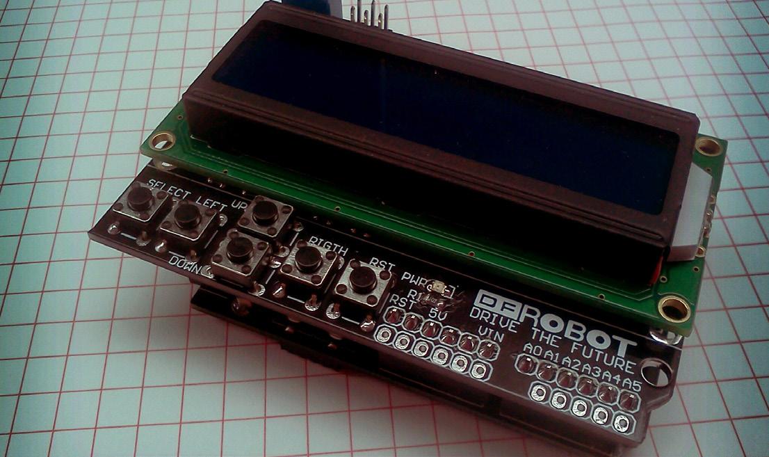
ARDUINO SHIELDS are the boards, which are plugged over the Arduino board to expand its functionalities. There are different varieties of shields used for various tasks, such as Arduino motor shields, Arduino communication shields, etc.
The shield is defined as the hardware device that can be mounted over the board to increase the capabilities of the projects. It also makes our work easy. For example, Ethernet shields are used to connect the Arduino board to the Internet.
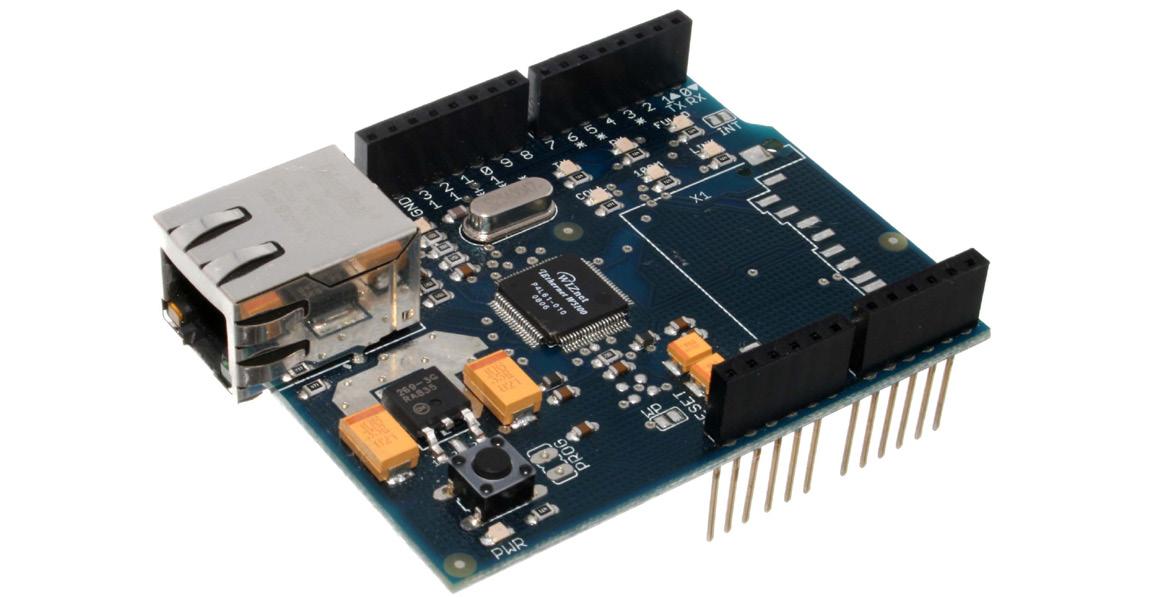
The pin position of the shields is similar to the Arduino boards. We can also connect the modules and sensors to the shields with the help of the connection cable. Arduino motor shields help us to control the motors with the Arduino board.
The advantages of using Arduino shields are listed below:
• It adds new functionalities to the Arduino projects.
• The shields can be attached and detached easily from the Arduino board. It does not require any complex wiring.
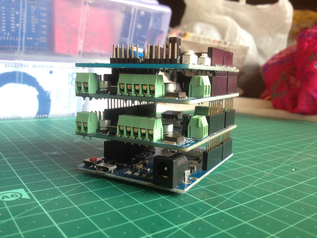
• It is easy to connect the shields by mounting them over the Arduino board.
• The hardware components on the shields can be easily implemented.[15]

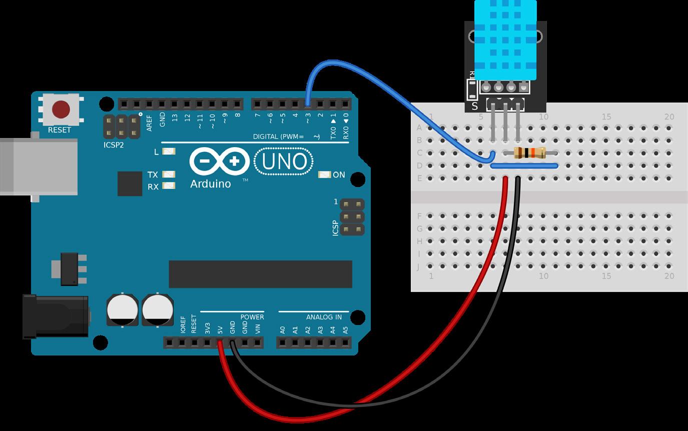
A sensor is a device that produces an output signal for the purpose of sensing a physical phenomenon. In the broadest definition, a sensor is a device, module, machine, or subsystem that detects events or changes in its environment and sends the information to other electronics, frequently a computer processor. Sensors are always used with other electronics.[16]
• Monolithic integrated, high voltage, high current, 4-channel driver
• You can use DC motors and power supplies of up to 36 Volts
• The chip can supply a maximum current of 600mA per channel
• The L293D chip is also what’s known as a type of H-Bridge
• The H-Bridge is typically an electrical circuit that enables a voltage to be applied across a load in either direction to an output, e.g. motor
Features:
• 8-Bit Serial-In, Parallel-Out Shift Register
• Wide Operating Voltage Range of 2 V to 6 V
• High-Current 3-State Outputs Can Drive Up To 15 LSTTL Loads
• Low Power Consumption, 80-µA Max ICC
• Typical tpd = 13 ns
• Low Input Current of 1
• Shift Register Has Direct Clear
Firstly insert the pins into the connectors and make sure that the pins are all the way in. After the pins are inserted do not, and I repeat myself, do not forget to tighten the screws. If the pin isn’t fully tightened it could create a spark and/or it could just fall out and cause a short circuit.
We are connecting the HC-05 bluetooth module. Connecting the bluetooth module is very easy and requires just beginner level soldering skills. Just follow the schematics we have provided to you. Don’t forget to look at the names of the pins and don’t mix it up.

Imagine you are in that period of life when you are really interested in robotics and want to build your own DIY robot. After doing some research you’ve got to know that accomplishing your goal is not that difficult. On the Internet you found a lot of info about Arduino, Raspberry Pi and other hardware. You compared all the pros and cons of hardware and decided to buy Arduino Uno microcontroller. Finally, after 6 weeks of waiting you received your sacred delivery parcel. You unpacked it and touched for the first time ever your own Arduino Uno microcontroller. Immediately, you’ve got an idea how to use that robot. You are devoted to the idea of creating an RC Car. You’ve managed to construct the car correctly, but now the most interesting part only begins. For proper programming of your car’s microcontroller you need to follow some basic rules of coding.
Firstly, you need to understand some basics like what’s code, schematics etc.
Let’s try to reveal these unknown words. Code basically means program instructions. For coding we use different programming languages for example: C++, Java, Python, HTML5 and others.
A schematic is a template-based code generator that supports complex logic. It is a set of instructions for transforming a software project by generating or modifying code. Schematics are packaged into collections and installed with npm. The schematic collection can be a powerful tool for creating, modifying, and maintaining any software project, but is particularly useful for customizing Angular projects to suit the particular needs of your own organization. You might use schematics, for example, to generate commonly-used UI patterns or specific components, using predefined templates or layouts. Use schematics to enforce architectural rules and conventions, making your projects consistent and intraoperative.
So when you understand basic things in programming, let’s begin the process.
STEP 1
You have to download the Arduino IDE app from the official website.
STEP 2 Install the app.
After this step there will be 2 pathways that you can follow.
Let’s discuss the first scenario (A).
STEP 3A
Watch some Arduino code tutorials. Those videos will help you with that.
STEP 4A Get acquainted with the program by creating some simple codes.
STEP 5A
When you realize that you are ready, you can start coding your car.

STEP 6A
Connect your computer to the Arduino microcontroller using a special USB cable.
STEP 7A Verify the code and then upload it.
STEP 8A Check the robot if it works.
STEP 9A*
If there are any issues, then try to fix them. Issues could be associated with any part of your project. So check everything.
STEP 10A*
Go to STEP 8A.
Let’s discuss the second scenario (B).
STEP 3B
Google for some working code or code parts.
STEP 4B Adjust it if needed.
STEP 5B
Verify and upload the code.
STEP 6B
Check the robot if it works.
STEP 7B*
If there are any issues, then try to fix them. Issues could be associated with any part of your project. So check everything.
STEP 8B*
Go to STEP 6B.
Incase of your RC car project, you can just use the code from: https://create.arduino.cc/projecthub/isum-sathmira/bluetooth-car-6dab7a
Any free Android app that can send serial command via bluetooth may be used for control. Bluetooth RC Car by Andi.Co Android application was used during the project: https://play.google.com/store/apps/details?id=braulio.calle. bluetoothRCcontroller&hl=en&gl=US&pli=1
If you did everything correctly and constructed your car properly, then you’ll have an amazing working robot that is being controlled by a bluetooth supporting device (for example your phone).

[1] DEFINITION robotics (2021). https://www.techtarget.com/whatis/definition/robotics
[2] Three Laws of Robotics (2022). Wikipedia. https://en.wikipedia.org/wiki/Three_ Laws_of_Robotics
[3] Shakey the Robot (2022). SRI International. https://www.sri.com/hoi/shakey-therobot/
[4] Shakey the robot (2022). Wikipedia. https://en.wikipedia.org/wiki/Shakey_the_ro bot
[5] Eight Rules of Robotic Safety (2022). Solano Community College. http://bcs.sola no.edu/ewylie/cis112testreviews/roboticsaftey.html
[6] What is electricity (2022). AEP Energy. https://www.aepenergy.com/blog/ what-is-electricity/ [7] Electricity explained. The science of electricity (2021). U.S. Energy Information Administration. https://www.eia.gov/energyexplained/electricity/the-science-of-elec tricity.php
[8] Electricity explained. How electricity is generated (2022). U.S. Energy Informa tion Administration. https://www.eia.gov/energyexplained/electricity/how-electrici ty-is-generated.php
[9] History of Electricity (2022). Ankara Üniversitesi Açık Ders Malzemeleri. https://acikders.ankara.edu.tr/pluginfile.php/88993/mod_resource/content/1/History%20 of%20Electricity%20-%20Resimsiz.pdf
[10] History of electrical engineering (2022). Wikipedia. https://en.wikipedia.org/ wiki/History_of_electrical_engineering
[11] Electric charge (2022). LawAspect. https://lawaspect.com/electric-charge/ [12] Alternating current & Direct current (2015). European Commission website. https://ec.europa.eu/health/scientific_committees/opinions_layman/electromagnet ic-fields2015/en/glossary/abc/alternating-current.htm
[13] Brushed DC electric motor (2022). Wikipedia. https://en.wikipedia.org/wiki/ Brushed_DC_electric_motor
[14] Arduino Uno (2022). Wikipedia. https://en.wikipedia.org/wiki/Arduino_Uno [15] Arduino Shields (2022). JavaTpoint. https://www.javatpoint.com/arduino-shields [16] Sensor (2022). Wikipedia. https://en.wikipedia.org/wiki/Sensor
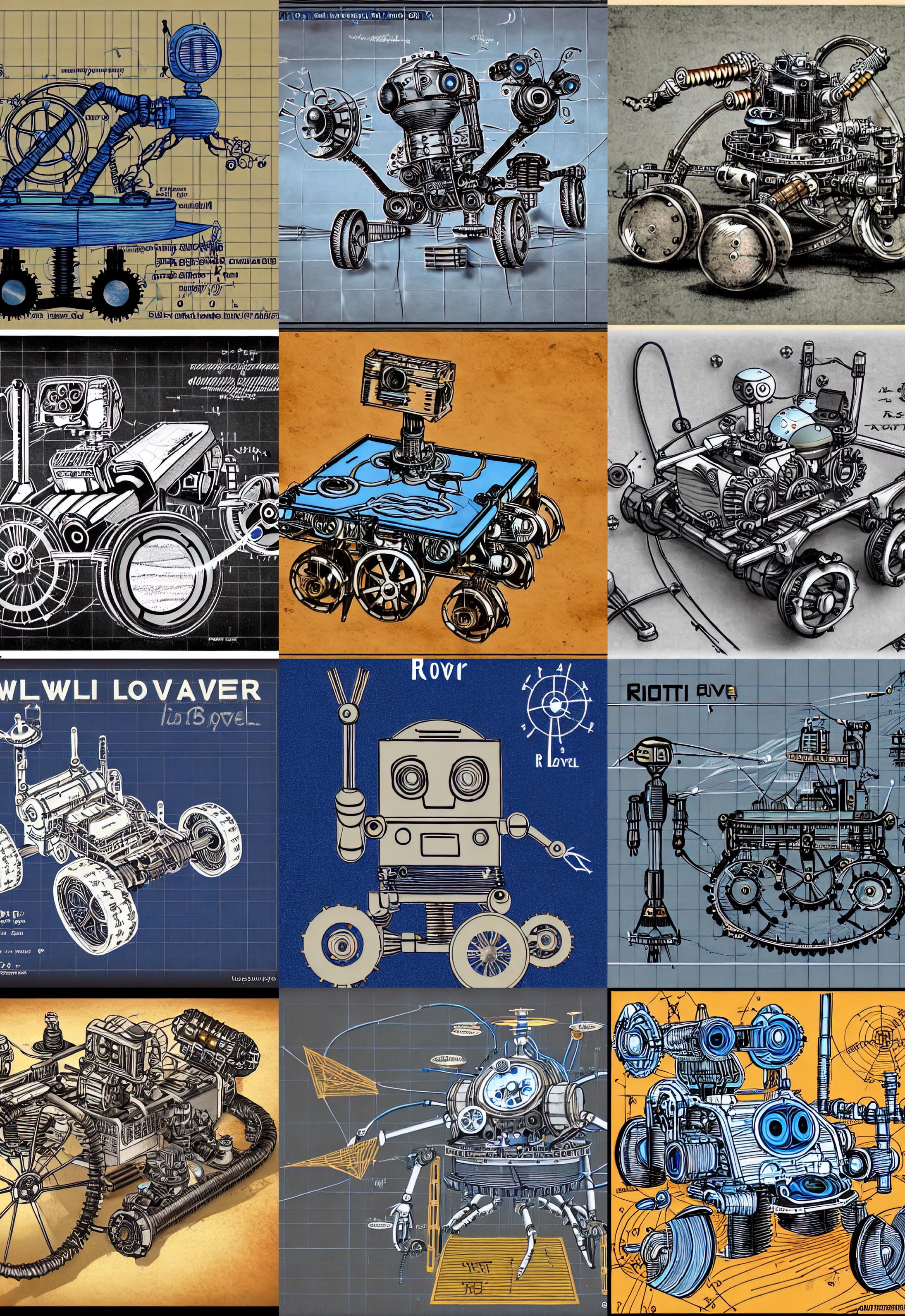
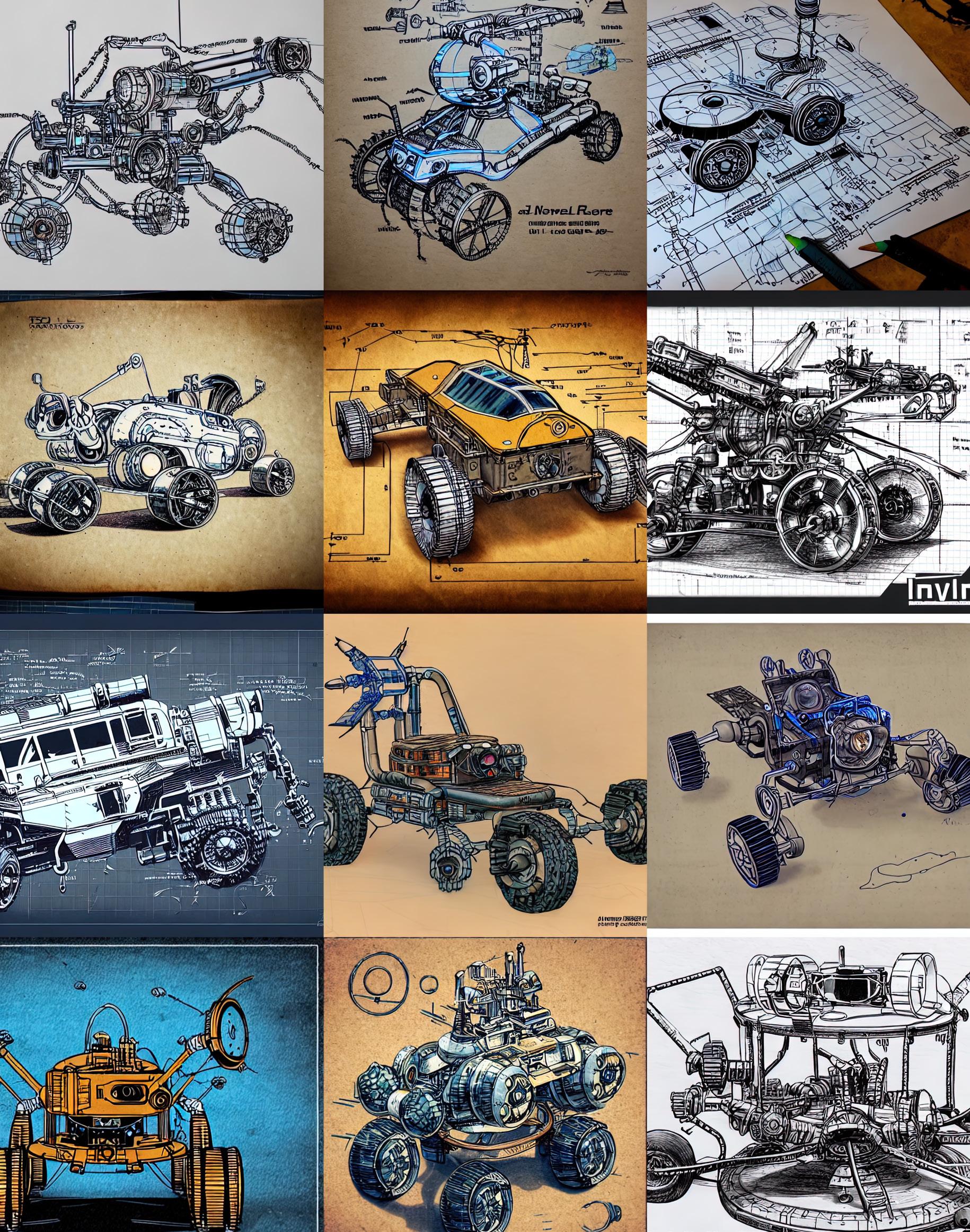
All the illustrative graphics (without reference) were generated by Monica Păunescu and Liviu Puzdercă, facilitators of the “Race To Employment” project, using Artificial Inteligence “text to image” algorithm Stable Diffusion on local runtime with RTX 3090 graphics card. Various combinations and seeds [sic!] of the following text prompt were used: “I will never leave you, prototype, offroad, robot rover, blueprint, cyborg brain, steampunk, industrial, mechanism, retro-futurist, space probe, voyager, photography, hq, 8k, manga, graphics, aquaforte, cartoon, anime, color drawing, ink, stencil, electric, schematic, color pencil drawing”
The European Commission support for the production of this publication does not constitute an endorsement of the contents which reflects the views only of the authors, and the Commission cannot be held responsible for any use which may be made of the information contained therein.

